EP0286994B1 - Method and arrangement for the detection of surface flaws - Google Patents
Method and arrangement for the detection of surface flaws Download PDFInfo
- Publication number
- EP0286994B1 EP0286994B1 EP88105660A EP88105660A EP0286994B1 EP 0286994 B1 EP0286994 B1 EP 0286994B1 EP 88105660 A EP88105660 A EP 88105660A EP 88105660 A EP88105660 A EP 88105660A EP 0286994 B1 EP0286994 B1 EP 0286994B1
- Authority
- EP
- European Patent Office
- Prior art keywords
- light
- test specimen
- strip
- accordance
- recording
- Prior art date
- Legal status (The legal status is an assumption and is not a legal conclusion. Google has not performed a legal analysis and makes no representation as to the accuracy of the status listed.)
- Expired - Lifetime
Links
Images


Classifications
-
- G—PHYSICS
- G01—MEASURING; TESTING
- G01B—MEASURING LENGTH, THICKNESS OR SIMILAR LINEAR DIMENSIONS; MEASURING ANGLES; MEASURING AREAS; MEASURING IRREGULARITIES OF SURFACES OR CONTOURS
- G01B11/00—Measuring arrangements characterised by the use of optical techniques
-
- G—PHYSICS
- G01—MEASURING; TESTING
- G01B—MEASURING LENGTH, THICKNESS OR SIMILAR LINEAR DIMENSIONS; MEASURING ANGLES; MEASURING AREAS; MEASURING IRREGULARITIES OF SURFACES OR CONTOURS
- G01B11/00—Measuring arrangements characterised by the use of optical techniques
- G01B11/24—Measuring arrangements characterised by the use of optical techniques for measuring contours or curvatures
- G01B11/245—Measuring arrangements characterised by the use of optical techniques for measuring contours or curvatures using a plurality of fixed, simultaneously operating transducers
-
- G—PHYSICS
- G01—MEASURING; TESTING
- G01N—INVESTIGATING OR ANALYSING MATERIALS BY DETERMINING THEIR CHEMICAL OR PHYSICAL PROPERTIES
- G01N21/00—Investigating or analysing materials by the use of optical means, i.e. using sub-millimetre waves, infrared, visible or ultraviolet light
- G01N21/84—Systems specially adapted for particular applications
- G01N21/88—Investigating the presence of flaws or contamination
- G01N21/8806—Specially adapted optical and illumination features
-
- G—PHYSICS
- G01—MEASURING; TESTING
- G01N—INVESTIGATING OR ANALYSING MATERIALS BY DETERMINING THEIR CHEMICAL OR PHYSICAL PROPERTIES
- G01N21/00—Investigating or analysing materials by the use of optical means, i.e. using sub-millimetre waves, infrared, visible or ultraviolet light
- G01N21/84—Systems specially adapted for particular applications
- G01N21/8422—Investigating thin films, e.g. matrix isolation method
- G01N2021/8427—Coatings
-
- G—PHYSICS
- G01—MEASURING; TESTING
- G01N—INVESTIGATING OR ANALYSING MATERIALS BY DETERMINING THEIR CHEMICAL OR PHYSICAL PROPERTIES
- G01N21/00—Investigating or analysing materials by the use of optical means, i.e. using sub-millimetre waves, infrared, visible or ultraviolet light
- G01N21/84—Systems specially adapted for particular applications
- G01N21/88—Investigating the presence of flaws or contamination
- G01N21/8851—Scan or image signal processing specially adapted therefor, e.g. for scan signal adjustment, for detecting different kinds of defects, for compensating for structures, markings, edges
- G01N2021/8887—Scan or image signal processing specially adapted therefor, e.g. for scan signal adjustment, for detecting different kinds of defects, for compensating for structures, markings, edges based on image processing techniques
-
- G—PHYSICS
- G01—MEASURING; TESTING
- G01N—INVESTIGATING OR ANALYSING MATERIALS BY DETERMINING THEIR CHEMICAL OR PHYSICAL PROPERTIES
- G01N21/00—Investigating or analysing materials by the use of optical means, i.e. using sub-millimetre waves, infrared, visible or ultraviolet light
- G01N21/84—Systems specially adapted for particular applications
- G01N21/88—Investigating the presence of flaws or contamination
- G01N21/95—Investigating the presence of flaws or contamination characterised by the material or shape of the object to be examined
- G01N21/9515—Objects of complex shape, e.g. examined with use of a surface follower device
-
- G—PHYSICS
- G01—MEASURING; TESTING
- G01N—INVESTIGATING OR ANALYSING MATERIALS BY DETERMINING THEIR CHEMICAL OR PHYSICAL PROPERTIES
- G01N2201/00—Features of devices classified in G01N21/00
- G01N2201/10—Scanning
- G01N2201/102—Video camera
Landscapes
- Physics & Mathematics (AREA)
- General Physics & Mathematics (AREA)
- Health & Medical Sciences (AREA)
- Life Sciences & Earth Sciences (AREA)
- Chemical & Material Sciences (AREA)
- Analytical Chemistry (AREA)
- Biochemistry (AREA)
- General Health & Medical Sciences (AREA)
- Immunology (AREA)
- Pathology (AREA)
- Investigating Materials By The Use Of Optical Means Adapted For Particular Applications (AREA)
- Length Measuring Devices By Optical Means (AREA)
Description
Die Erfindung betrifft ein Verfahren und eine Vorrichtung zur Überprüfung der glänzenden Oberflächen eines Prüflings auf Oberflächenfehler nach dem Oberbegriff von Anspruch 1 (Verfahren) bzw. von Anspruch 6 (Vorrichtung).The invention relates to a method and a device for checking the shiny surfaces of a test specimen for surface defects according to the preamble of claim 1 (method) and of claim 6 (device).
Derartige Verfahren und Vorrichtungen sind beispielsweise aus der DE-PS 34 18 317 bekannt. Sie sind mit dem Nachteil verbunden, daß bestimmte und insbesondere kleinere Oberflächenfehler wegen geringer Kontraste bei der Auswertung des durch Oberflächenfehler beeinflußten reflektierten Lichts nur schwer erkennbar sind. Dies ist beispielsweise dann der Fall, wenn der Glanzgrad der zu prüfenden Oberfläche nicht optimal ist.Such methods and devices are known for example from DE-PS 34 18 317. They have the disadvantage that certain and, in particular, smaller surface defects are difficult to detect because of low contrasts when evaluating the reflected light influenced by surface defects. This is the case, for example, when the gloss level of the surface to be tested is not optimal.
Gemäß der vorerwähnten DE-PS 34 18 317 wurde bereits vorgeschlagen, zur Durchführung des eingangs genannten Verfahrens mehrere nebeneinanderliegende Leuchtreihen vorzusehen. Durch die Erzeugung mehrerer voneinander abgesetzter Lichtstreifen auf der zu untersuchenden Oberfläche sollte bei einer Relativbewegung zwischen dieser Oberfläche und der Beleuchtungsanordnung ein Oberflächenfehler nacheinander mehrere Lichtstreifen durchwandern und durch wiederholtes Aufscheinen in den aufeinanderfolgenden Lichtstreifen visuell leichter erkennbar werden. Dieses Verfahren erfordert jedoch vom Prüfpersonal fortwährend höchste Aufmerksamkeit und ist daher auf Dauer sehr ermüdend, ohne daß eine hinreichende Gewähr für ein weitgehend lückenloses Erfassen auch von schwieriger erkennbaren Fehlern gegeben ist.According to the aforementioned DE-PS 34 18 317, it has already been proposed to provide a plurality of light rows lying next to one another in order to carry out the method mentioned at the beginning. By generating a plurality of stripes of light that are set apart from one another on the surface to be examined, a relative error between this surface and the lighting arrangement should cause a surface defect to pass through several stripes of light in succession and be made easier to visually recognize by repeated appearance in the successive stripes of light. However, this procedure requires the highest attention from the test personnel and is therefore very tiring in the long run, without a sufficient guarantee for a largely complete recording of even more difficult to detect errors.
Gemäß der US-PS 4,629,319 wurde auch schon vorgeschlagen, bei der flächenhaften Ausleuchtung von Oberflächen zur Fehlererkennung eine Kontrasterhöhung im reflektierten Meßlicht durch Verwendung von sog. Retrofolien zu erzielen, die in den Strahlengang des reflektierten Lichtes eingebracht werden und das auf eine solche Folie auftreffende Licht mit einer gewissen Streucharakteristik zurückwerfen, worauf es nach nochmaliger Reflexion an der zu überprüfenden Oberfläche in eine Videokamera gelangt. Dieses Verfahren erfordert jedoch einen großen Einfallswinkel für das Meßlicht, was den Raumbedarf für die gesamte Prüfanordnung erheblich vergrößert, so daß der praktische Einsatz bei beengten räumlichen Verhältnissen auf dem Prüfstand Schwierigkeiten bereitet. Außerdem führen bei der Prüfung gewölbter Oberflächen Änderungen in der Topografie infolge des großen Einfallswinkels des Meßlichts rasch zu erheblichen Verzerrungen, die einer sicheren Fehlerkennung entgegenstehen.According to US Pat. No. 4,629,319, it has also already been proposed to achieve a contrast increase in the reflected measurement light in the areal illumination of surfaces for error detection by using so-called retrofoils which are introduced into the beam path of the reflected light and the light impinging on such a film throw back with a certain scattering characteristic, after which it comes into a video camera after being reflected again on the surface to be checked. However, this method requires a large angle of incidence for the measuring light, which considerably increases the space required for the entire test arrangement, so that practical use in the confined space on the test stand presents difficulties. In addition, changes in the topography due to the large angle of incidence of the measuring light quickly lead to considerable distortions when checking curved surfaces, which prevent reliable error detection.
In der Zeitschrift "Journal of the Institution of Electrical Engineers", Vol. 9, Juli 1963, Seiten 296 bis 299 wird ein optisches Prüfverfahren für rasch bewegte, galvanisch verzinkte Blechbänder beschrieben, bei dem einzelne Standbilder der Blechoberfläche mittels eines rotierenden Polygonspiegels erzeugt und video-optisch ausgewertet werden. Die Fehler an galvanischen Verzinnungen zeigen sich an einem veränderten Glanzgrad der Oberfläche und können als mehr oder weniger starke Intensitätsänderungen gegenüber der einwandfreien Zinnoberfläche festgestellt werden.In the journal "Journal of the Institution of Electrical Engineers", Vol. 9, July 1963, pages 296 to 299, an optical test method for rapidly moving, galvanized sheet metal strips is described, in which individual still images of the sheet surface are generated by means of a rotating polygon mirror and video - be evaluated optically. The defects in galvanic tinning are shown by a change in the gloss level of the surface and can be determined as more or less strong changes in intensity compared to the perfect tin surface.
Die GB-PS 2,085,255 zeigt eine Einrichtung zum selbsttätigen video-optischen Erkennen von Eisenbahnwaggons während der Vorbeifahrt, wobei mittels eines rotierenden Polygonspiegels der Aufnahmestrahl synchron mit dem Waggon mitbewegt wird und so von dessen Seitenwand eine Serie von sich überlappenden Standbildern erzeugt wird, die hinsichtlich Identifizierungszeichen der Waggons, die auf die Seitenwand des Waggons großflächig aufgemalt sind, ausgewertet werden.GB-PS 2,085,255 shows a device for the automatic video-optical detection of railway wagons while driving past, the recording beam being moved synchronously with the wagon by means of a rotating polygon mirror, and thus a series of overlapping still images is generated from the side wall of the wagon, with regard to identification marks of the wagons, which are largely painted on the side wall of the wagon, are evaluated.
Der Erfindung liegt die Aufgabe zugrunde, ein Verfahren und eine Vorrichtung der eingangs genannten Art zu schaffen, das eine sichere Detektierung von Fehlern an oder in Oberflächen von Kraftfahrzeugen und anderen Gegenständen ermöglicht, und zwar auch dann, wenn die Oberfläche, wie im Fall der Vorlackierung bei Kraftfahrzeug-Karosserien, matt ist und daher eine stärkere Streuung des reflektierten Lichtes bewirkt. Trotzdem soll die Prüfanordnung raumsparend und daher vielseitig einsetzbar sein und die Gestehungskosten überwiegend in den elektronischen Bereich verlegen, in dem im allgemeinen mit deutlicher Kostendegression zu rechnen ist. Darüber hinaus soll eine einfache, das Prüfpersonal weitgehend entlastende Handhabung der Prüfanordnung erzielt werden.The invention has for its object to provide a method and a device of the type mentioned that enables reliable detection of defects on or in surfaces of motor vehicles and other objects, even if the surface, as in the case of pre-painting in motor vehicle bodies, is matt and therefore causes a greater scatter of the reflected light. Nevertheless, the test set-up should be space-saving and therefore versatile, and the production costs should mainly be shifted to the electronic area, in which significant cost degression can generally be expected. In addition, a simple handling of the test arrangement, which largely relieves the test personnel, is to be achieved.
Diese Aufgabe wird erfindungsgemäß bezüglich des Verfahrens durch die kennzeichnenden Merkmale von Anspruch 1 und bezüglich der Vorrichtung durch die kennzeichnenden Merkmale von Anspruch 6 gelöst. Dank der Beobachtung des auf der Prüflingsoberfläche erzeugten Lichtstreifens zeichnen sich Lackfehler darin als dunkle Stellen ab, die mit geringem Aufwand detektiert und lokalisiert werden können.This object is achieved with respect to the method by the characterizing features of
Zweckmäßige Ausgestaltungen der Erfindung können den jeweiligen abhängigen Ansprüchen entnommen werden.Appropriate embodiments of the invention can be found in the respective dependent claims.
Ein Ausführungsbeispiel einer bevorzugten Ausführungsform des erfindungsgemäßen Verfahrens und der erfindungsgemäßen Vorrichtung zur Erkennung von Lackfehlern auf der Karosserie von Kraftfahrzeugen ist im folgenden anhand der beigefügten Zeichnungen näher beschrieben. Darin zeigen
Figur 1- einen Prüfstand zur Oberflächen-Fehlererkennung in der Ansicht und mit Rechnern in schematischer Darstellung,
- Fig. 2
- den Prüfstand von Fig. 1 in vergrößerter Darstellung mit Sensoreinheiten in schematischer Darstellung,
- Fig. 3
- eine Beleuchtungseinheit und eine Sensoreinheit aus Fig. 2 in detaillierter Darstellung,
- Fig. 4
- die Beleuchtungs- und Sensoreinheiten von Fig. 3 in der Ansicht von unten,
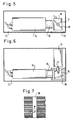
- Fig. 5
- die Sensorteinheit aus Fig. 3 in vergrößerter Darstellung,
- Fig. 6
- die Sensorteinheit von Fig. 5 in der Ansicht von oben,
- Fig. 7
- die Wiedergabe eines auf einem Monitor der Sensoreinheit erscheinenden Bildes von der Abtastung der geprüften Oberfläche.
- Figure 1
- a test stand for surface defect detection in the view and with computers in a schematic representation,
- Fig. 2
- 1 in an enlarged representation with sensor units in a schematic representation,
- Fig. 3
- 2 shows a lighting unit and a sensor unit from FIG. 2 in a detailed illustration,
- Fig. 4
- 3 in the view from below,
- Fig. 5
- 3 in an enlarged view,
- Fig. 6
- 5 in the view from above,
- Fig. 7
- the reproduction of an image appearing on a monitor of the sensor unit from the scanning of the tested surface.
In Fig. 1 und 2 ist ein Prüfstand mit einem Gestell 1 dargestellt, das beispielsweise durch miteinander verschraubte Rohren oder Profilteile gebildet ist. In den Innenraum des Gestells 1 ist als kreisbogenförmige Linie ein Portal 2 eingezeichnet. Längs dieser kreisbogenförmigen Linie sind jeweils mehrere Beleuchtungseinheiten 3 und Sensoreinheiten 4 angeordnet. Diese Einheiten sind am Geräteaufbau 1 mit nicht dargestellten Haltearmen derart befestigt, daß ihre Anordnung längs der kreisbogenförmigen Linie des Portals 2 gewährleistet ist. Die Beleuchtungseinheiten 3 bilden insgesamt ein Beleuchtungssystem, während die Sensoreinheiten 4 insgesamt ein Aufzeichnungssystem bilden, wie dies nachfolgend näher beschrieben wird.1 and 2, a test stand is shown with a
Das Portal 2 ist so dimensioniert, daß auf einem Transportschlitten 5 die Karosserie 6 eines Personenkraftwagens durch das Portal senkrecht zur Zeichenebene von Fig. 1 und 2 hindurchgeführt werden kann und von diesem Portal überspannt wird, wobei die Karosserie mit den Flanken- und Dachpartien einen etwa gleichmäßigen Abstand zu den jeweils gegenüberliegenden Portalsektoren einhält. In Fig. 1 und 2 ist die Karosserie 6 des Kraftwagens in ihrer jeweils linken Hälfte mit der Frontseite und in ihrer jeweils rechten Hälfte mit der Heckseite gezeigt. Sie ist ohne Räder mit nicht dargestellten Lagermitteln auf den Transportschlitten 5 aufgesetzt. Der Schlitten 5 kann mit der auf ihn aufgesetzten Kraftwagen-Karosserie 6 auf nicht dargestellten, senkrecht zur Zeichenebene verlaufenden Schienen langsam und möglichst gleichmäßig durch das Portal 2 hindurchgefahren werden, wozu er mit einem ebenfalls nicht dargestellten Kettenantrieb versehen ist.The
Längs der kreisbogenförmigen Linie des Portals 2 befinden sich ca. 30 unter sich gleich gestaltete Beleuchtungseinheiten 3. Eine dieser Beleuchtungseinheiten ist in Fig. 3 und 4 näher dargestellt.Along the arcuate line of the
Die Beleuchtungseinheit 3 weist in einem schachtartigen Gehäuse 7, dessen Flächen mattschwarz lackiert sind, eine Halogenlampe 8 auf, die kaltverspiegelt ist und einen Lichtkegel von ca. ± 20° erzeugt. Das von der Lampe 8 ausgehende Licht fällt auf einen Spezialreflektor 9, der zur optischen Achse der Lampe 8 unter einem Winkel von ca. 45° geneigt ist und das Licht zu einem Austrittsfenster 10 lenkt, das am schachtartigen Gehäuse 7 angeordnet ist und durch welches das Licht auf die Oberfläche der Karosserie 6 des Kraftwagens gelenkt wird. Der Reflektor 9 wirkt für Lichtstrahlenkomponenten parallel zur Zeichenebene von Fig. 3 wie ein Spiegel und für Lichtstrahlenkomponenten senkrecht zur Zeichenebene wie ein Diffusor.In a shaft-like housing 7, the surfaces of which are painted matt black, the lighting unit 3 has a halogen lamp 8, which is cold-reflecting and generates a light cone of approximately ± 20 °. The light coming from the lamp 8 falls on a special reflector 9, which is inclined to the optical axis of the lamp 8 at an angle of approximately 45 ° and directs the light to an exit window 10 which is arranged on the shaft-like housing 7 and through which the Light is directed onto the surface of the
Die Richtung, in welcher die Kraftwagen-Karosserie 6 durch das Portal 2 hindurchbewegt wird, ist in Fig. 3 und 4 durch den Pfeil 11 markiert. Das Lichtaustrittsfenster 10 ist parallel zum Pfeil 11 verhältnismäßig schmal, hat jedoch senkrecht hierzu eine relativ große Ausdehnung.The direction in which the
Die Beleuchtungseinheiten 3 sind am Portal 2 derart angeordnet, daß die Lichtaustrittsfenster 10 benachbarter Beleuchtungseinheiten 3 mit ihren Schmalseiten aneinanderstoßen, so daß längs der Linie des Portals 2 ein durchgehendes schmales Lichtband entsteht, das der Portallinie in einem Polygonzug näherungsweise folgt. Wird die Karosserie 6 auf dem Schlitten 5 durch das Portal 2 hindurchgeführt, so wird das jeweils unter dem Portal 2 befindliche Querschnittsprofil der Karosserie gleichmäßig beleuchtet in Form eines schmalen, durchgehenden Lichtbandes, das sich auf dem zum obigen Querschnittsprofil gehörigen schmalen Abschnitt der Oberfläche 12 der Karosserie 6 senkrecht zur Transportrichung vom unteren Rand der einen Flanke über das Dach bzw. Haubenteil bis zum unteren Rand der anderen Flanke der Karosserie erstreckt. Das auf der Karosserie-Oberfläche 12 erzeugte Lichtband hat eine Breite von ca. 50 bis 100 mm. Beim Hindurchführen durch das Portal wandert die Karosserie 6 unter diesem Lichtband hindurch und wird von ihm jeweils streifenweise beleuchtet.The lighting units 3 are arranged on the
Ferner befindet sich am Portal 2 dicht neben den Beleuchtungseinheiten 3 eine Anzahl von 26 Sensoreinheiten 4, die zur streifenweisen optischen Abtastung und Aufzeichnung von Bildern der von den Beleuchtungseinheiten 3 beleuchteten Oberflächenabschnitte der Karosserie 6 dienen. Die Sensoreinheiten 4 sind auf dem Portalbogen derart verteilt angeordnet, daß sie mit ihrem Aufnahmewinkel insgesamt alle Teilabschnitte des Querschnittsprofils der Karosserie 6 lückenlos erfassen. Dabei dienen zur Erfassung der linken und rechten Flankenflächen der Karosserie 6 die Sensoreinheiten L1 bis L6 bzw. R1 bis R6, während für die Erfassung der nach oben gerichteten Dach- und Haubenflächen die Sensoreinheiten D1 bis D7 bzw. H1 bis H7 dienen. Die Sensoreinheiten 4 sind unter sich im wesentlichen gleich ausgebildet. Sie unterscheiden sich lediglich hinsichtlich der Fokussierung der in ihnen enthaltenen, weiter unten näher beschriebenen Aufnahmekameras auf unterschiedliche Abstände der von ihnen erfaßten Karosseriebereiche, um zu berücksichtigen, daß die Bereiche der Motor- und Kofferraumhauben der Karosserie vom Portalbogen einen größeren Abstand haben als die Dach- und Seitenbereiche.Furthermore, a number of 26 sensor units 4 are located on the
Eine der Sensoreinheiten 4 ist ebenfalls in Fig. 3 und 4 näher dargestellt. Sie umfaßt eine Montageplatte 13, auf der eine mit einem Flächen-CCD ausgestattete Videokamera 14 mit einem Aufnahmeobjektiv 15 sowie eine Abtasteinheit (Scanner) 16 mit einem um eine Achse 17 drehbaren Abtastspiegel 18 angeordnet sind. Die in einer Matrix angeordneten CCD-Elemente der Videokamera 13 bilden optoelektronische Wandler zur fernsehgerechten Umwandlung der empfangenen analogen Lichtsignalen in elektrische Digitalsignale. Ferner trägt die Montageplatte 12 ein entspiegeltes Lichteintrittsfenster 19, hinter dem der Abtastspiegel 18 der Abtasteinheit 16 angeordnet ist. Der Abtastspiegel 18 lenkt das von der Lampe 8 ausgehende und von der Oberfläche 12 der Karosserie 6 reflektierte Licht nach Durchtritt durch das Lichteintrittsfenster 19 in das Objektiv 15 der Kamera 14 um.One of the sensor units 4 is also shown in more detail in FIGS. 3 and 4. It comprises a mounting
Der Abtastspiegel 18 der Abtasteinheit 16 wird rechnergesteuert durch ein nicht näher dargestelltes Antriebssystem angetrieben und hat eine Winkelgeschwindigkeit von ca. 0,5 Umdrehungen pro Minute. Er kompensiert die Bewegungsunschärfe, die bei der Aufnahme der Karosserie-Oberfläche 12 während der Förderbewegung durch den Schlitten 5 ohne eine derartige Kompensation entstehen würde. Darüber hinaus können Unregelmäßigkeiten in der Fördergeschwindigkeit des Schlittens 5 bei ruckartigem Antrieb durch eine entsprechende zusätzliche Regelung der Bewegung des Abtastspiegels 18 ausgeglichen werden, wenn z. B. durch einen an sich bekannten und nicht dargestellten Tachogenerator am Ritzel einer den Schlitten 5 antreibenden Kette derartige Geschwindigkeitsschwankungen registriert und entspechende Signale in die Scanner-Steuerung aller Sensoreinheiten 4 eingegeben werden.The
Wenn sich in gewölbten Oberflächenbereichen der Karosserie 6 der Einfallswinkel für das von den Beleuchtungeinheiten 3 kommende Abtastlicht beim Fördern der Karosserie durch das Portal 2 ändert, wandert das auf die Bildmitte eines an die Videokamera 14 angeschlossenen Monitors eingestellte Bild des auf der Karosserie erzeugten Lichtbandes aus der Bildmitte aus. Um dies zu verhindern, hat die Abtasteinheit 16 der Sensoreinheit 4 auch noch die Aufgabe, durch entsprechende Ansteuerung des Abtastspiegels 18 ein solches Auswandern des Lichtband-Bildes aus der Bildmitte des Monitors zu verhindern.If the angle of incidence for the scanning light coming from the lighting units 3 changes when the body is conveyed through the portal 2 in curved surface areas of the
Die Montageplatte 13 ist lösbar an eine Trägerplatte 20 angesetzt, die unter Verwendung bekannter und daher nicht dargestellter Befestigungsmittel an einem Winkelträger 21 justierbar angeordnet ist. Der Winkelträger 21 wiederum befindet sich an einer Armatur 22, mit der die Sensoreinheit 4 am Portal 2 befestigt ist.The mounting
Die Sensoreinheit 4 wird vor dem Ansetzen an die Trägerplatte 20 vorjustiert und danach durch Justierung der Trägerplatte 20 gegenüber dem Winkelträger 21 endgültig justiert. Diese Endjustage ist unabhängig vom jeweiligen Typ des zu prüfenden Fahrzeuges. Ist die Endjustage erzielt, kann die Trägerplatte 20 gegen weitere Verstellung gegenüber dem Winkelträger 21 durch Verkleben, Verschrauben oder Verstiften gesichert werden. Dies hat den Vorteil, daß eine defekte Sensoreinheit 4 von der Trägerplatte 20 abgenommen und durch eine neue, gleichartige und vorjustierte Sensoreinheit ersetzt werden kann, ohne die Justage der Gesamtanordnung zu verlieren.The sensor unit 4 is pre-adjusted before being attached to the carrier plate 20 and then finally adjusted by adjusting the carrier plate 20 relative to the angle carrier 21. This final adjustment is independent of the type of vehicle to be tested. Once the final adjustment has been achieved, the carrier plate 20 can be secured against further adjustment relative to the angle carrier 21 by gluing, screwing or pinning. This has the advantage that a defective sensor unit 4 can be removed from the carrier plate 20 and replaced by a new, similar and pre-adjusted sensor unit without losing the adjustment of the overall arrangement.
Die Justage der Gesamtanordnung jeder Sensoreinheit 4 am Portal 2 erfolgt derart, daß sich die Aufnahmebereiche der Videokameras von benachbart angeordneten Sensoreinheiten auf der Oberfläche 12 der Karosserie 6 überlappen, wie dies aus Fig. 2 ersichtlich ist. Hierdurch wird erreicht, daß bei der nachfolgend näher beschriebenen Überprüfung der Karosserie-Oberfläche auf Lackfehler kein Teilbereich dieser Oberfläche ausgelassen wird und ungeprüft bleibt. Darüber hinaus ist bei der Justage darauf zu achten, daß das Bild des auf der Karosserie-Oberfläche erzeugten Lichtbandes, das auf den an die Videokameras angeschlossenen Monitoren erscheint, etwa in der Bildmitte liegt, wenn senkrecht zum Querschnittsprofil der Karosserie orientierte Oberflächenbereiche erfaßt werden. Das Weglaufen des Lichtbandes aus der Bildmitte bei gewölbten Oberflächenbereichen wird - wie bereits erwähnt - durch die Rechnersteuerung der Abtasteinheit 18 verhindert.The overall arrangement of each sensor unit 4 on the
Wie aus Fig. 3 und 4 ersichtlich ist, sind am Portal 2 die Beleuchtungseinheiten 3 und die Sensoreinheiten 4 dicht nebeneinander angeordnet, so daß die Lichteintrittsfenster 19 der Sensoreinheiten 4 dicht neben den Lichtaustrittsfenstern 10 der Beleuchtungseinheiten 3 in einer Ebene liegen. Das von den Beleuchtungseinheiten 3 ausgehende Licht wird somit an der Karosserie-Oberfläche 12 unter einem sehr kleinen Reflexionswinkel zu den Sensoreinheiten 4 reflektiert. Dadurch bleiben Verzerrungen an den konvexen und konkaven Oberflächenbereichen der Karosserie 6 gering.As can be seen from FIGS. 3 and 4, the lighting units 3 and the sensor units 4 are arranged close to one another on the
Die Videokamera jeder Sensoreinheit 4 ist an je einen separaten Kamerarechner angeschlossen. Diese Kamerarechner, welche dem handelsüblichen Rechnerangebot entstammen können, sind, wie aus Fig. 1 ersichtlich ist, in einem ersten Schaltschrank 23 untergebracht. Allerdings kann bei der in Fig. 2 gezeigten Ausführungsform mit 26 Sensoreinheiten die Anzahl der Kamerarechner von 26 auf 19 Stück reduziert werden, wenn die Rechner der Kameras der Sensoreinheiten D1 bis D7, welche zur Abtastung der Dachflächen der Karosserie 6 dienen, wechselweise auch an die Kameras der Sensoreinheiten H1 bis H7, die zur Abtastung der Haubenflächen der Karosserie 6 dienen, angeschlossen werden. Dies ist möglich, weil sich Dach- und Haubenflächen der Karosserie 6 in der Draufsicht von oben nicht überschneiden und deshalb die Sensoreinheiten D1 bis D7 und die Sensoreinheiten H1 bis H7 niemals gleichzeitig, sondern stets wechselweise in Funktion treten. Die Rechner der Kameras steuern die Abtasteinheiten 18 der Sensoreinheiten 4 und werten die von ihren Videokameras erzeugten Bildsignale aus.The video camera of each sensor unit 4 is connected to a separate camera computer. These camera computers, which can originate from the commercially available range of computers, are accommodated in a
Die Ausgangssignale der im Schaltschrank 23 angeordneten Kamerarechner gehen an 3 Zwischenrechner, die gemäß Fig. 1 in einem Schaltschrank 24 untergebracht sind und die Daten der Sensorgruppen L1 bis L6, R1 bis R6 und D1/H1 bis D7/H7 weiter aufarbeiten, bis sie an einen Großrechner 25 weitergegeben werden. Die im Schaltschrank 24 installierten Monitore können wechselweise auf alle Sensoreinheiten 4 geschaltet werden, um das Originalbild zu überwachen.The output signals of the camera computers arranged in the
Im Großrechner 25 erfolgt die Zusammenfassung aller Meßdaten. Er ist mit einer Datenausgabestation ausgestattet, welche Informationen von detektierten Oberflächenfehlern ausdruckt.In the
Mit dieser Anordnung läuft nun ein Prüfgang folgendermaßen ab. Die auf Lackfehler zu prüfende Karosserie 6 eines Kraftwagens wird außerhalb des Portals 2 auf den entsprechend weit verfahrbaren Schlitten 5 aufgesetzt, vorzugsweise mit der Frontseite zum Portal hin. Anschließend werden die Beleuchtungseinheiten 3 und Sensoreinheiten 4 sowie der Antrieb für den Schlitten 5 eingeschaltet, worauf sich die Karosserie 6 auf dem Schlitten 5 in das Portal 2 hineinbewegt und dieses mit der Fördergeschwindigkeit des Schlittenantriebs durchläuft. Bei der beschriebenen Ausführungsform beträgt die Fördergeschwindigkeit des Schlittens 5 etwa 50 - 100 mm/sec.With this arrangement, a test run now proceeds as follows. The
Dabei wandert relativ zur Karosserie 6 das schmale Lichtband, das von den Beleuchtungeinheiten 3 erzeugt wird, über die Oberfläche 12 der Karosserie 6 hinweg und beleuchtet in einem Querschnittsprofil der Karosserie jeweils einen schmalen Streifen von 50 - 100 mm Breite. Die auf dem jeweiligen Querschnittsprofil unter dem Lichtband liegenden Abschnitte der Karosserie-Oberfläche 12 werden von je einer Videokamera 14 der Sensoreinheiten 4 erfaßt.Relative to the
Die im Schaltschrank 23 angeordneten Kamerarechner veranlassen automatisch, daß die ihnen zugeordneten Videokameras jeweils gleichzeitig alle 10 mm des Karosserie-Vorschubes durch das Portal 2 hindurch ein Bild der jeweils erfaßten Karosserie-Oberflächenabschnitte aufnehmen. Bei einer Vorschubgeschwindigkeit im oben erwähnten Bereich (50 - 100 mm/sec) führt dies zu ca. 5 Bildern pro Sekunde. Hat die Karosserie 6 eine übliche Länge von 4 m, so liefert demnach jede Videokamera während des Durchlaufs einer Karosserie durch das Portal 2 schrittweise eine Gesamtzahl von 400 Aufnahmen, d. h. es werden schrittweise 400 Querschnittsprofile zwischen dem frontseitigen und dem heckseitigen Ende der Karosserie 6 abgetastet und aufgezeichnet. Da diese Aufzeichnungen in Schritten von jeweils 10 mm aufeinanderfolgen und das zur Abtastung auf der Karosserie-Oberfläche 12 erzeugte Lichtband eine Breite von 50 bis 100 mm aufweist, ist wegen der im Vergleich zur Breite des Lichtbandes wesentlich geringeren Schrittweite der Aufzeichnungsfolgen sichergestellt, daß kein Abschnitt der Karosserie-Oberfläche 12 unerfaßt bleibt. Im Gegenteil, die zeitlich aufeinanderfolgenden Bilder der Oberflächenabschnitte überlappen sich in ihrem Bildinhalt jeweils um ca. 70 %.The camera computers arranged in the
Um eine aufwendige Belichtungssteuerung in den Objektiven der Videokameras 14 der Sensoreinheiten 4 zu vermeiden, können die Lampen 8 aller Beleuchtungseinheiten 3 gemeinsam derart gesteuert oder geregelt werden, daß die Intensität des von ihnen ausgehenden und von der Oberfläche 12 der Karosserie 6 zurückgeworfenen Lichtes der helleren oder dunkleren Farbe der Karosserie-Lackierung angepaßt wird. Dadurch kann die Intensität des in die Videokameras einfallenden Lichtes in allen Fällen in etwa konstant gehalten werden.In order to avoid complex exposure control in the lenses of the
Auf den Monitoren, die auf die Videokameras 14 der Sensoreinheiten 4 aufgeschaltet werden können, erscheinen Fehler auf der Oberfläche der Karosserie 6 entweder als dunkle Stellen im hellen Bild des auf der Karosserie 6 erzeugten Lichtbandes oder als Änderungen in der Kontur des Bildes dieses Lichtbandes. Eine Aufnahme eines solchen Monitorbildes zeigt Fig. 7. Darin ist das Bild des Lichtbandes mit 26 bezeichnet, worin ein Lackfehler als dunkle Stelle 27 erscheint.On the monitors, which can be connected to the
Die Daten der von den Videokameras 14 der Sensoreinheiten 4 gleichzeitig aufgezeichneten Teilbilder der einzelnen Oberflächenabschnitte des jeweils erfaßten Querschnittsprofils und die Daten der so erfaßten Bilder der nacheinander unter dem Lichtband hindurchwandernden Querschnittsprofile der Karosserie 6 werden in den Rechnern weiterverarbeitet und zu einem Gesamtbild zusammengesetzt, das von der Datenausgabestation des Rechners 25 beispielsweise als Hardcopy-Ausdruck ausgegeben wird und über etwaige Fehler auf der gesamten Oberfläche der Karosserie 6 und über die Koordinaten dieser Fehlerstellen Aufschluß gibt.The data of the partial images of the individual surface sections of the respective cross-sectional profile recorded simultaneously by the
Anhand dieser Informationen können die mit der obigen Anlage detektierten Fehler auf der Oberfläche der untersuchten Karosserie durch das mit der Fehlerbeseitigung beauftragte Personal auch dann leicht aufgefunden und beseitigt werden, wenn die visuelle Erkennung dieser Fehler an sich schwierig ist.On the basis of this information, the faults detected by the above system on the surface of the body under investigation can easily be found and eliminated by the personnel commissioned with the fault rectification even if it is difficult to visually recognize these faults per se.
Damit Oberflächenfehler, die auf der Oberfläche 12 der Karosserie 6 im Überlappungsbereich der Videokameras 14 zweier benachbart angeordneter Sensoreinheiten 4 liegen, durch das beschriebene System nicht doppelt gemeldet werden, kann folgendes Verfahren angewendet werden.The following method can be used so that surface defects which lie on the
Vor der Inbetriebnahme der vorgeschlagenen Anordnung zur Erkennung von Oberflächenfehlern der serienmäßig zu untersuchenden Karosserien eines bestimmten Fahrzeugtyps wird zunächst ein hell-farbiges Karosserie-Muster dieses Fahrzeugtyps nacheinander vorzugsweise an vier Stellen (vorderer Bereich, Türbereich, hinterer Bereich) in das Portal 2 gestellt und jeweils mit dem von den Beleuchtungseinheiten 3 erzeugten Lichtband beleuchtet. In der ersten dieser vier Positionen werden jeweils die beiden Monitorbilder benachbarter Sensoreinheiten 4 beobachtet, so daß ungefähr in der Mitte des Überlappungsbereiches eine Markierung, z. B. mit schwarzem Filzstift, auf der Muster-Karosserie angebracht werden kann, was auf den Monitorbildern mitverfolgt und kontrolliert werden kann. In dieser Weise werden die Überlappungsbereiche aller Sensoreinheiten L1/2 bis R2/R1 des Portals auf der Muster-Karosserie markiert. Die gleichen Markierungsarbeiten werden in den folgenden zweiten bis vierten Positionen der Muster-Karosserie wiederholt. So erhält man z. B. an jeder Seitenwand der Muster-Karosserie 20 Markierungspunkte, die in 5 Zeilen angeordnet sind. Anschließend werden jeweils von Hand die vier in jeder Zeile angeordneten Markierungspunkte zu einer von vorn nach hinten durchgezogenen schwarzen Linie verbunden, wozu keine besondere Sorgfalt angewendet werden muß. Somit wird die Gesamtfläche des Muster-Karosserie an den beiden Seitenflächen und an den Dach-und Haubenflächen mit insgesamt 16 von vorn nach hinten verlaufenden Markierungslinien überzogen. Diese so markierte Muster-Karosserie wird nun aus dem Portal 2 herausgefahren und anschließend erneut in das Portal 2 eingeführt und in einem regulären Prüfgang, wie er oben beschrieben wurde, durch das Portal 2 hindurchgeführt.Before the proposed arrangement for recognizing surface defects of the bodywork of a particular vehicle type to be examined in series is put into operation, a light-colored bodywork pattern of this vehicle type is first placed in the
Ein spezielles Inbetriebnahmeprogramm der Rechner erkennt nun in jedem Bild, das von den Sensoreinheiten 4 erzeugt wird, maximal 2 Markierungslinien und legt damit jeweils exakt den Meßbereich jeder Sensoreinheit 4 an jeder Stelle der Karosserie-Oberfläche des durch die markierte Muster-Karosserie repräsentierten Fahrzeugtyps fest.A special commissioning program of the computers now recognizes a maximum of 2 marking lines in each image generated by the sensor units 4 and thus precisely defines the measuring range of each sensor unit 4 at each point on the body surface of the vehicle type represented by the marked sample body.
Der Meßbereich der Videokameras 14 von jeweils zwei benachbart angeordneten Sensoreinheiten 4 wird also mit diesem Inbetriebnahmeprogramm so beschränkt, daß der Meßbereich der einen Kamera unterhalb und der Meßbereich der anderen Kamera oberhalb ein und derselben Markierungslinie bleibt.The measuring range of the
Nach diesem Inbetriebnahmeprogramm kann die reguläre Untersuchung der serienmäßig vom Montageband kommenden Karosserien des betreffenden Fahrzeugtyps aufgenommen werden, wie dies oben beschrieben wurde. Wegen der mittels der Muster-Karosserie durchgeführten Begrenzung der an sich überlappenden Meßbereiche der Videokameras unterbleibt eine doppelte Fehlererfassung, ohne daß die mit der vorgeschlagenen Anordnung serienmäßig geprüften Karosserien erneut markiert werden müssen.After this start-up program, the regular examination of the bodies of the vehicle type in question, which come off the assembly line as standard, can be started, as described above. Because of the limitation of the overlapping measuring ranges of the video cameras, which is carried out by means of the sample body, a double error detection does not take place, without the bodies which have been tested with the proposed arrangement having to be marked again.
Die nach dem oben beschriebenen Verfahren markierte Muster-Karosserie dient somit zum Referieren der Anlage und wird für eventuelle spätere Nachjustierungen aufbewahrt.The sample body marked using the procedure described above is used for referencing the system and is kept for possible later readjustments.
Selbstverständlich ist es erforderlich, für jeden Fahrzeugtyp, der sich hinsichtlich der Gestaltung seiner Karosserie von anderen Fahrzeugtypen unterscheidet, eine eigene Muster-Karosserie zu schaffen und die Anlage mittels des jeweiligen Inbetriebnahmeprogramms softwaremäßig darauf einzustellen.Of course, it is necessary to create a separate sample body for each vehicle type that differs from other vehicle types with regard to the design of its body and to set the system accordingly in software using the respective commissioning program.
Anstatt den beweglich gelagerten Schlitten 5 mit der Karosserie 6 durch das feststehende Portal 2 hindurchzuführen, kann auch die Karosserie 6 ortsfest bleiben und das Portal 2 nach Ausstattung mit einem Schienenfahrwerk über die Karosserie 6 hinwegbewegt werden. Wesentlich ist nur, daß zwischen der Karosserie 6 und dem Portal 2 mit den Beleuchtungseinheiten 3 und den Sensoreinheiten 4 eine Relativbewegung stattfindet.Instead of guiding the movably mounted
Mit der vorgeschlagenen Anlage können auch die Front- und Heckseiten der Karosserie von Fahrzeugen auf Oberflächenfehler untersucht werden, wenn hierfür zusätzliche und geeignet angeordnete Sensoreinheiten vor bzw. hinter dem Portal 2 vorgesehen werden.The proposed system can also be used to examine the front and rear sides of the body of vehicles for surface defects if additional and suitably arranged sensor units are provided in front of or behind the
Schließlich eignen sich das erfindungsgemäße Verfahren und die erfindunngsgemäße Vorrichtung bei entsprechender Anpassung auch zur Erkennung von Fehlern an Oberflächen anderer industriell hergestellter Gegenstände, beispielsweise von Gegenständen aus Flach- oder Hohlglas, Keramik, Kunststoff, etc. oder von Küchengeräten und sonstigen Gebrauchsgütern, von denen der Erwerber oder Benutzer einwandfreie Oberflächen erwartet.Finally, the method according to the invention and the device according to the invention, with appropriate adaptation, are also suitable for the detection of defects on surfaces of other industrially manufactured objects, for example objects made of flat or hollow glass, ceramic, plastic, etc. or kitchen appliances and other consumer goods, of which the Buyers or users expect flawless surfaces.
Claims (13)
- Process for the examination of a glossy surface (12) of a test specimen (6) for surface faults, preferably for the examination of the painted surface of bodywork of a motor vehicle (6) for paint faults, in which- a strip of light (26) is produced on the surface (12) of the test specimen (6) by means of diffuse light emitted from a fixed lighting system,- the test specimen (6) is moved past an observation point, and- the length of the strip of light (26) extends across the test specimen transverse to the direction of movement,characterised in that,a) the width of the strip of light (26) amounts to about 50 to 100 mm,b) the observation - seen in the direction of movement (11) - occurs from a position laying immediately behind or in front of the lighting system (3) in such a way that light rays which are reflected at a relatively small angle from the surface of the test specimen (12) are recorded,c) the observation occurs by means of a video camera (14) which has an optical-electronic converter for the conversion of analogue light signals into digital electrical signals,d) strip-shaped sections of the surface of the test specimen (12) are recorded stepwise each time in the region of the strip of light (26), whereby the step-width of the sequential recordings is smaller than the width of the strip of light (26) and the images of the surface sections, following one another in time, overlap one another in their image content,e) to identify surface faults (27), the data from the images recorded by the video camera (14) is evaluated for intensity changes in a computer (23).
- Process in accordance with Claim 1, characterised in that, the path of the rays to the video camera (14) is swung around in a way which compensates for movement blur during the recording time for one stepwise recording, for which purpose the transitional speed of the test specimen (6) is continuously recorded.
- Process in accordance with Claim 1 or 2, characterised in that, the path of the rays to the video camera (14) can be controlled by a drive in such a way that compensation is made for the change of angle in the topography of the surface of the test specimen (12) which occurs from one recording step to the next recording step, and the strip of light which is (26) produced on the surface of the test specimen (12) and which is to be recorded is prevented from moving away from the recording region of the video camera (14).
- Process in accordance with Claim 1, 2 or 3, characterised in that, a contour line of the strip of light (26) produced on the surface of the test specimen (12) is recorded in the stepwise recording and is evaluated for changes in the course of the line.
- Process in accordance with one of the Claims 1 to 4, characterised in that, the entire surface region of the test specimen (6) not facing the support (5) is examined by a multiplicity of simultaneously executed illuminations and observations (3, 4) which are adjacent to one another and transverse to the direction of transition (11) along an arch (portal 2) extending over the transitional route of the test specimen (6) which extends - transverse to the direction of transition (11) - over a peripheral region of more than the recordable width of one single observation system and lighting system (Figure 2).
- Device for examining a glossy surface of a test specimen for surface faults, preferably for the examination of the surface of the painted bodywork of a motor vehicle (6) for paint faults, especially for carrying out the process in accordance with Claim 1, with- a fixed lighting system (3) emitting diffuse light for producing a strip of light (26) on the surface (12) of the test specimen (6) and- a transportation device (5) for moving the test specimen (6) past an observation point (6),characterised in that,a) the lighting system (3) has a lighting unit with a light exit window (10) to produce the strip of light (26), whereby the light exit window (10) has a relatively large elongation transverse to the direction of movement (11) and is relatively narrow in the direction of movement (11), and by this means a strip of light (26) about 50 to 100 mm wide can be produced on the surface of the test specimen,b) as seen in the direction of movement (11) and immediately behind or in front of the light exit window, a recording system with a video camera (14) is arranged which includes the optical-electronic converter for converting the analogue light signals which are reflected at a relatively small angle from the surface of the test specimen (12),c) a scanning unit (16) is provided comprising a mirror (18) which can be moved with the movement of the test specimen (12), whereby the mirror deflects the light reflected from the surface of the test specimen (12) into the lens (15) of the video camera (14),d) a control device, provided for the video camera (14) and the scanning device (16), controls these in such a way that the strip-shaped sections of the surface of the test specimen (12) are recorded stepwise each time in the region of the strip of light (26), whereby the step-width of the sequential recordings is smaller than the width of the strip of light (26) and the images, following one another in time, overlap one another in their image content,e) a computer (23) is provided which evaluates the data from the images recorded by the video camera for changes in intensity, so that surface faults may be recognised.
- Device in accordance with Claim 6, characterised in that, the lighting unit of the lighting system (3) comprises a lamp (8) and a reflector (9), which functions as a mirror in the rotational direction of the reflector (9) and functions as a diffuser in the direction transverse to the plane of rotation.
- Device in accordance with Claim 6 or 7, characterised in that, the lighting system comprises several lighting units (3) which are placed transversely to the transitional direction (11) immediately following one another, and which together produce a continuous band of light.
- Device in accordance with Claim 8, characterised in that, the several lighting units (3) arranged adjacent to one another form a portal (2) which stretches over the test specimen (6).
- Device in accordance with Claim 8 or 9, characterised in that, the light intensity of the several lighting units (3) can be controlled together.
- Device in accordance with one of the Claims 6 to 10, characterised in that, the recording system comprises a drive unit (16) for a moveable mirror (18) arranged between the video camera (14) and the test specimen (6).
- Device in accordance with one of the Claims 8 to 11, characterised in that, several recording systems are provided whose recording regions on the surface of the test specimen, measured transversely to the transitional direction (11), adjoin one another in the peripheral direction.
- Device in accordance with Claim 12, characterised in that, the computers (23) assigned to the recording systems (4) are connected to a further computer (25) which generates an overall image from the individual images recorded by the individual recording systems.
Applications Claiming Priority (2)
| Application Number | Priority Date | Filing Date | Title |
|---|---|---|---|
| DE19873712513 DE3712513A1 (en) | 1987-04-13 | 1987-04-13 | METHOD AND DEVICE FOR DETECTING SURFACE DEFECTS |
| DE3712513 | 1987-04-13 |
Publications (3)
| Publication Number | Publication Date |
|---|---|
| EP0286994A2 EP0286994A2 (en) | 1988-10-19 |
| EP0286994A3 EP0286994A3 (en) | 1990-03-14 |
| EP0286994B1 true EP0286994B1 (en) | 1994-07-20 |
Family
ID=6325542
Family Applications (1)
| Application Number | Title | Priority Date | Filing Date |
|---|---|---|---|
| EP88105660A Expired - Lifetime EP0286994B1 (en) | 1987-04-13 | 1988-04-08 | Method and arrangement for the detection of surface flaws |
Country Status (6)
| Country | Link |
|---|---|
| US (1) | US4918321A (en) |
| EP (1) | EP0286994B1 (en) |
| JP (1) | JP2578897B2 (en) |
| CA (1) | CA1285331C (en) |
| DE (1) | DE3712513A1 (en) |
| ES (1) | ES2059421T3 (en) |
Families Citing this family (66)
| Publication number | Priority date | Publication date | Assignee | Title |
|---|---|---|---|---|
| CA2070822A1 (en) * | 1989-12-05 | 1991-06-06 | Herbert Barg | Process and arrangement for optoelectronic measuring of objects |
| US5041726A (en) * | 1990-06-11 | 1991-08-20 | Hughes Aircraft Company | Infrared holographic defect detector |
| DE4206868A1 (en) * | 1992-03-05 | 1993-09-09 | Hermann Dr Ing Tropf | Photographing moving objects with video camera - provides scanning mirror in beam path between object and camera with deflection such that movement of object image is compensated |
| US5414518A (en) * | 1992-08-10 | 1995-05-09 | Chrysler Corporation | Method and apparatus for the evaluation of reflective surfaces |
| US5471307A (en) * | 1992-09-21 | 1995-11-28 | Phase Shift Technology, Inc. | Sheet flatness measurement system and method |
| JP3172287B2 (en) * | 1992-11-09 | 2001-06-04 | マツダ株式会社 | Film defect detector |
| JPH08184567A (en) * | 1994-10-05 | 1996-07-16 | Musco Corp | Device and method for inspecting mirror reflection surface or half-mirror reflection surface |
| IL113428A0 (en) * | 1995-04-20 | 1995-07-31 | Yissum Res Dev Co | Glossmeter |
| DE19544481A1 (en) * | 1995-11-29 | 1997-06-05 | Laser Sorter Gmbh | Lighting device with metal halide lamps |
| JP2976869B2 (en) * | 1995-12-28 | 1999-11-10 | 日産自動車株式会社 | Surface defect inspection equipment |
| US5686987A (en) * | 1995-12-29 | 1997-11-11 | Orfield Associates, Inc. | Methods for assessing visual tasks to establish desirable lighting and viewing conditions for performance of tasks; apparatus; and, applications |
| US6462813B1 (en) * | 1996-04-12 | 2002-10-08 | Perceptron, Inc. | Surface defect inspection system and method |
| AU4375797A (en) * | 1996-08-22 | 1998-03-06 | Dr. Ing Willing Gmbh | Device for visually inspecting the surface condition of large-dimension surfaces to be matched |
| US6033503A (en) * | 1997-05-05 | 2000-03-07 | Steven K. Radowicz | Adhesive sensing assembly for end jointed beam |
| DE19730885A1 (en) | 1997-07-18 | 1999-01-21 | Audi Ag | Process for the automatic detection of surface defects on body-in-white bodies and device for carrying out the process |
| DE19754547B4 (en) * | 1997-12-09 | 2007-04-12 | Bayerische Motoren Werke Ag | Method for determining the hiding power of a coating |
| DE19754549A1 (en) * | 1997-12-09 | 1999-06-10 | Bayerische Motoren Werke Ag | Fault-testing of dull unfinished vehicle chassis provided with light-colored filler |
| DE19816992A1 (en) | 1998-04-17 | 1999-11-04 | Daimler Chrysler Ag | Method for marking at least one point on an object |
| DE19842112B4 (en) * | 1998-09-07 | 2006-12-14 | Braun, Uwe Peter, Dipl.-Ing. | Device for setting and controlling the illuminance of control lights |
| DE19855478B4 (en) * | 1998-12-01 | 2006-01-12 | Steinbichler Optotechnik Gmbh | Method and device for optical detection of a contrast line |
| GB9826802D0 (en) * | 1998-12-04 | 1999-01-27 | Vdrs Limited | Vehicle inspection system |
| JP2001004347A (en) * | 1999-06-22 | 2001-01-12 | Mitsubishi Electric Corp | Defect inspecting device |
| DE19930688A1 (en) * | 1999-07-02 | 2001-01-04 | Byk Gardner Gmbh | Surface quality determination device for car bodywork, comprises illuminating device containing light emitting diode and device capturing light reflected from surface which contains photosensor, filter between them modifying light |
| US6266138B1 (en) | 1999-10-12 | 2001-07-24 | Perceptron, Inc. | System and method for detecting defects in a surface of a workpiece |
| FI19992761A (en) * | 1999-12-22 | 2001-06-23 | Visy Oy | Procedure for checking the condition of a transport vehicle |
| DE10110994B4 (en) * | 2000-03-09 | 2012-11-29 | Isra Vision Systems Ag | Device for image scanning of an object |
| DE10242620B3 (en) | 2002-09-13 | 2004-04-15 | Dr.Ing.H.C. F. Porsche Ag | Method and device for the visual detection of color gloss deviations |
| DE10261865A1 (en) * | 2002-12-20 | 2004-07-15 | Uwe Braun Sonnenlichtleitsysteme Lichtsysteme Gmbh | Method, device and computer program for optical surface detection |
| KR100742003B1 (en) * | 2003-10-21 | 2007-07-23 | 다이하츠고교 가부시키가이샤 | Surface defect inspecting method and device |
| DE102004007829B4 (en) * | 2004-02-18 | 2007-04-05 | Isra Vision Systems Ag | Method for determining areas to be inspected |
| DE102004007828B4 (en) * | 2004-02-18 | 2006-05-11 | Isra Vision Systems Ag | Method and system for inspecting surfaces |
| JP2006305426A (en) * | 2005-04-26 | 2006-11-09 | Suzuki Motor Corp | Method, apparatus and computer program for application state inspection |
| DE102007013883A1 (en) * | 2007-03-20 | 2008-10-30 | Beulenzentrum Jentgens Gmbh & Co. Kg | Damage i.e. hail damage, detecting and examining method for body of motor vehicle, involves detecting damages by scanning surface of motor vehicle while scanning devices i.e. laser scanners, are moved automatically relative to surface |
| CN101755200A (en) * | 2007-04-16 | 2010-06-23 | 何塞普·托内罗·蒙特塞拉特 | Utilization clears off the system that looks like to detect the defective in the surface by combined diagram |
| DE102007034689B4 (en) * | 2007-07-12 | 2009-06-10 | Carl Zeiss Ag | Method and device for optically inspecting a surface on an object |
| SG157977A1 (en) * | 2008-06-23 | 2010-01-29 | Semiconductor Tech & Instr Inc | System and method for inspection of semiconductor packages |
| DE102008064562A1 (en) | 2008-12-29 | 2010-07-08 | Carl Zeiss Oim Gmbh | Device for optically inspecting an at least partially shiny surface on an object |
| US9418496B2 (en) * | 2009-02-17 | 2016-08-16 | The Boeing Company | Automated postflight troubleshooting |
| US9541505B2 (en) | 2009-02-17 | 2017-01-10 | The Boeing Company | Automated postflight troubleshooting sensor array |
| US8812154B2 (en) * | 2009-03-16 | 2014-08-19 | The Boeing Company | Autonomous inspection and maintenance |
| DE102009021733A1 (en) | 2009-05-12 | 2010-12-30 | Carl Zeiss Oim Gmbh | Apparatus and method for optically inspecting an article |
| US9046892B2 (en) * | 2009-06-05 | 2015-06-02 | The Boeing Company | Supervision and control of heterogeneous autonomous operations |
| US8773289B2 (en) | 2010-03-24 | 2014-07-08 | The Boeing Company | Runway condition monitoring |
| US8599044B2 (en) | 2010-08-11 | 2013-12-03 | The Boeing Company | System and method to assess and report a health of a tire |
| US8712634B2 (en) | 2010-08-11 | 2014-04-29 | The Boeing Company | System and method to assess and report the health of landing gear related components |
| RU2549140C2 (en) * | 2010-08-13 | 2015-04-20 | Арве Сервис Гмбх | Preparation vehicles for servicing |
| US8982207B2 (en) * | 2010-10-04 | 2015-03-17 | The Boeing Company | Automated visual inspection system |
| JP2012098181A (en) * | 2010-11-02 | 2012-05-24 | Sumitomo Electric Ind Ltd | Device and method for detection |
| DE102011082178A1 (en) * | 2011-09-06 | 2013-03-07 | Hauni Maschinenbau Ag | Optical inspection of rod-shaped articles of the tobacco processing industry |
| US9117185B2 (en) | 2012-09-19 | 2015-08-25 | The Boeing Company | Forestry management system |
| EP2770322B1 (en) * | 2013-02-26 | 2019-01-16 | C.R.F. Società Consortile per Azioni | Method and system for detecting defects in painting of components, in particular of motor-vehicle bodies |
| DE102013109915B4 (en) * | 2013-09-10 | 2015-04-02 | Thyssenkrupp Steel Europe Ag | Method and device for checking an inspection system for detecting surface defects |
| CN106415248B (en) | 2013-10-24 | 2020-08-18 | 飞利浦灯具控股公司 | Defect inspection system and method |
| US10063758B2 (en) * | 2014-10-03 | 2018-08-28 | Davo Scheich | Vehicle photographic tunnel |
| KR101669998B1 (en) * | 2014-12-18 | 2016-10-28 | 대보정보통신 주식회사 | Ticket's pressure apparatus for cassette of ticket's machine |
| DE102015008409A1 (en) * | 2015-07-02 | 2017-01-05 | Eisenmann Se | Installation for optical inspection of surface areas of objects |
| ES2630736B1 (en) * | 2015-12-07 | 2018-07-04 | Universidad De Zaragoza | SYSTEM AND METHOD OF DETECTION OF DEFECTS IN SPECULAR OR SEMI-SPECULAR SURFACES THROUGH PHOTOGRAMETRIC PROJECTION |
| DE102016111544A1 (en) * | 2016-06-23 | 2017-12-28 | Hochschule Düsseldorf | Laser scanning system |
| CN110249617B (en) | 2016-12-07 | 2021-11-02 | 奥瓦德卡斯特姆规划有限责任公司 | Vehicle shooting room |
| DE102017108770A1 (en) * | 2017-04-25 | 2018-10-25 | Eisenmann Se | Installation for optical inspection of surface areas of objects |
| CZ201861A3 (en) * | 2018-02-05 | 2019-06-12 | Christoph Vávra | 3D analytical optical data meter |
| DE102018118602B3 (en) * | 2018-07-31 | 2019-11-28 | Sarma Aryasomayajula | Method and device for detecting and analyzing surface defects of three-dimensional objects with a reflective surface, in particular motor vehicle bodies |
| US11412135B2 (en) | 2018-12-05 | 2022-08-09 | Ovad Custom Stages, Llc | Bowl-shaped photographic stage |
| EP3792619B1 (en) * | 2019-09-11 | 2023-11-01 | Proov Station | Assembly for detecting faults on a body of a motor vehicle |
| CN113030100A (en) * | 2021-03-02 | 2021-06-25 | 成都小淞科技有限公司 | Coating flaw online automatic detection system |
| DE102021107115A1 (en) | 2021-03-23 | 2022-09-29 | B+M Surface Systems Gmbh | Device for examining a surface of a component |
Family Cites Families (21)
| Publication number | Priority date | Publication date | Assignee | Title |
|---|---|---|---|---|
| US3577039A (en) * | 1969-01-28 | 1971-05-04 | Bendix Corp | Optical apparatus for flaw detection |
| GB1379593A (en) * | 1971-05-21 | 1975-01-02 | Agfa Gevaert | Device for sensing a moving sheet material for imperfections |
| JPS5075483A (en) * | 1973-11-06 | 1975-06-20 | ||
| US4008606A (en) * | 1975-10-20 | 1977-02-22 | The United States Of America As Represented By The Secretary Of The Navy | Ship's bottom inspection apparatus |
| GB1592511A (en) * | 1977-05-18 | 1981-07-08 | Ferranti Ltd | Surface inspection apparatus |
| JPS5520123A (en) * | 1978-07-17 | 1980-02-13 | Nippon Pirooburotsuku Seizou K | Crack detector for bottle head |
| US4260899A (en) * | 1979-06-14 | 1981-04-07 | Intec Corporation | Wide web laser scanner flaw detection method and apparatus |
| US4345274A (en) * | 1980-10-08 | 1982-08-17 | Servo Corporation Of America | Object identification system utilizing closed circuit television |
| DE3111728A1 (en) * | 1981-03-25 | 1982-10-07 | Philips Patentverwaltung Gmbh, 2000 Hamburg | "TESTING PROCEDURE FOR WORKPIECES" |
| JPS5867093A (en) * | 1981-10-19 | 1983-04-21 | 株式会社東芝 | Method and device for inspecting printed circuit board |
| JPS58190707A (en) * | 1982-04-30 | 1983-11-07 | Toyoda Gosei Co Ltd | Surface inspecting method |
| US4563095A (en) * | 1982-12-20 | 1986-01-07 | Essex Group, Inc. | Method and apparatus for monitoring the surface of elongated objects |
| JPS59114445A (en) * | 1982-12-21 | 1984-07-02 | Yamamura Glass Kk | Apparatus for detecting defect of transparent body |
| US4528455A (en) * | 1983-05-13 | 1985-07-09 | Magnaflux Corporation | Non-destructive testing system with dual scanning |
| US4629319A (en) * | 1984-02-14 | 1986-12-16 | Diffracto Ltd. | Panel surface flaw inspection |
| DE3411578A1 (en) * | 1984-03-29 | 1985-10-10 | Licentia Patent-Verwaltungs-Gmbh, 6000 Frankfurt | Method for detecting flaws in coatings and device for carrying out the method |
| GB2159271B (en) * | 1984-04-27 | 1988-05-18 | Nissan Motor | Surface flaw detecting method and apparatus |
| DE3418317C1 (en) * | 1984-05-17 | 1985-01-31 | Daimler-Benz Ag, 7000 Stuttgart | Test chamber for checking the surface of vehicle bodies |
| JPS628045A (en) * | 1985-07-04 | 1987-01-16 | Nireko:Kk | Apparatus for detecting flaw |
| GB8517834D0 (en) * | 1985-07-15 | 1985-08-21 | Sira Ltd | Inspection apparatus |
| DE3534019A1 (en) * | 1985-09-24 | 1987-04-02 | Sick Optik Elektronik Erwin | OPTICAL RAILWAY MONITORING DEVICE |
-
1987
- 1987-04-13 DE DE19873712513 patent/DE3712513A1/en active Granted
-
1988
- 1988-04-08 EP EP88105660A patent/EP0286994B1/en not_active Expired - Lifetime
- 1988-04-08 ES ES88105660T patent/ES2059421T3/en not_active Expired - Lifetime
- 1988-04-13 JP JP63091233A patent/JP2578897B2/en not_active Expired - Lifetime
- 1988-04-13 US US07/180,936 patent/US4918321A/en not_active Expired - Lifetime
- 1988-04-13 CA CA000564075A patent/CA1285331C/en not_active Expired - Fee Related
Also Published As
| Publication number | Publication date |
|---|---|
| JPS6438638A (en) | 1989-02-08 |
| EP0286994A2 (en) | 1988-10-19 |
| EP0286994A3 (en) | 1990-03-14 |
| DE3712513A1 (en) | 1988-11-03 |
| US4918321A (en) | 1990-04-17 |
| JP2578897B2 (en) | 1997-02-05 |
| CA1285331C (en) | 1991-06-25 |
| ES2059421T3 (en) | 1994-11-16 |
| DE3712513C2 (en) | 1993-01-21 |
Similar Documents
| Publication | Publication Date | Title |
|---|---|---|
| EP0286994B1 (en) | Method and arrangement for the detection of surface flaws | |
| EP0228500B1 (en) | Method of and device for contactless measurement of the wheel profile of the wheels of railway wheel sets | |
| EP0836093B1 (en) | Method and apparatus for optical weld inspection | |
| EP1464920B1 (en) | Apparatus for detecting, determining and documenting damages, in particular deformations of painted surfaces caused by sudden events | |
| EP2326940B1 (en) | Device for testing the material of test objects by means of x-ray radiation | |
| DE102013112640B4 (en) | Door inspection system for a vehicle and inspection method for the same | |
| EP1805481B1 (en) | System and method for measuring a body and for monitoring the surface thereof | |
| DE19534145A1 (en) | Monitoring reflecting or semi-reflecting surface of object, for e.g. automatic on=line inspection of car body finish | |
| DE102010021853B4 (en) | Device and method for optical inspection of an object | |
| EP1245923A2 (en) | Procedure and device to determine and to verify the contour of a rim | |
| DE3809221A1 (en) | METHOD FOR DETECTING DEFECTS IN PRESSING PARTS OR OTHER WORKPIECES, AND DEVICE FOR IMPLEMENTING THE METHOD | |
| DE10328537A1 (en) | Metrology device comprises an optical arrangement for object dimension determination, whereby the object and the measurement device can be moved along an axis relative to each other and a light source and sensor are provided | |
| CH692665A5 (en) | Spinning preparation machine, for example, carding or carding. | |
| DE102007018204B4 (en) | Device for detecting defects in animal hides | |
| DE2613978C3 (en) | Measuring arrangement for checking the surface quality of a workpiece | |
| WO2019238689A1 (en) | Device for surface inspection of a motor vehicle and method for same | |
| AT407302B (en) | METHOD FOR MEASURING THE WALL THICKNESS OF A HOLLOW BODY PRODUCED FROM LIGHT-TRANSFERABLE MATERIAL | |
| EP2687837B1 (en) | Method and system for incident light inspection of at least two opposing top panel edges of a moving panel | |
| DE10104355A1 (en) | Image scanning device for object surface has image recording system positioned in dependence on horizontal position of scanned object for perpendicular scanning of object surface | |
| DE102005034637B4 (en) | Method and device for automated detection and evaluation of the states of motor vehicle body surfaces | |
| DE10102557A1 (en) | Detection of surface defects or inclusions within sheet material, especially sheet glass using a camera detection system arranged above the glass surface for recording multiple sectional images that can then be compared | |
| DE3703505C2 (en) | ||
| EP1862309B1 (en) | Sensor device | |
| DE102009009393A1 (en) | Device and method for measuring a body | |
| EP1398620B1 (en) | Method and apparatus for visual recognition of colour gloss deviations |
Legal Events
| Date | Code | Title | Description |
|---|---|---|---|
| PUAI | Public reference made under article 153(3) epc to a published international application that has entered the european phase |
Free format text: ORIGINAL CODE: 0009012 |
|
| AK | Designated contracting states |
Kind code of ref document: A2 Designated state(s): BE ES FR GB IT SE |
|
| RAP1 | Party data changed (applicant data changed or rights of an application transferred) |
Owner name: DAIMLER-BENZ AKTIENGESELLSCHAFT |
|
| PUAL | Search report despatched |
Free format text: ORIGINAL CODE: 0009013 |
|
| AK | Designated contracting states |
Kind code of ref document: A3 Designated state(s): BE ES FR GB IT SE |
|
| 17P | Request for examination filed |
Effective date: 19900208 |
|
| 17Q | First examination report despatched |
Effective date: 19910725 |
|
| ITF | It: translation for a ep patent filed |
Owner name: BARZANO' E ZANARDO ROMA S.P.A. |
|
| GRAA | (expected) grant |
Free format text: ORIGINAL CODE: 0009210 |
|
| AK | Designated contracting states |
Kind code of ref document: B1 Designated state(s): BE ES FR GB IT SE |
|
| GBT | Gb: translation of ep patent filed (gb section 77(6)(a)/1977) |
Effective date: 19940808 |
|
| ET | Fr: translation filed | ||
| REG | Reference to a national code |
Ref country code: ES Ref legal event code: FG2A Ref document number: 2059421 Country of ref document: ES Kind code of ref document: T3 |
|
| EAL | Se: european patent in force in sweden |
Ref document number: 88105660.0 |
|
| PLBE | No opposition filed within time limit |
Free format text: ORIGINAL CODE: 0009261 |
|
| STAA | Information on the status of an ep patent application or granted ep patent |
Free format text: STATUS: NO OPPOSITION FILED WITHIN TIME LIMIT |
|
| 26N | No opposition filed | ||
| REG | Reference to a national code |
Ref country code: GB Ref legal event code: 732E |
|
| PGFP | Annual fee paid to national office [announced via postgrant information from national office to epo] |
Ref country code: GB Payment date: 20000329 Year of fee payment: 13 |
|
| PGFP | Annual fee paid to national office [announced via postgrant information from national office to epo] |
Ref country code: BE Payment date: 20000425 Year of fee payment: 13 |
|
| PGFP | Annual fee paid to national office [announced via postgrant information from national office to epo] |
Ref country code: SE Payment date: 20000426 Year of fee payment: 13 |
|
| PG25 | Lapsed in a contracting state [announced via postgrant information from national office to epo] |
Ref country code: GB Free format text: LAPSE BECAUSE OF NON-PAYMENT OF DUE FEES Effective date: 20010408 |
|
| PG25 | Lapsed in a contracting state [announced via postgrant information from national office to epo] |
Ref country code: SE Free format text: LAPSE BECAUSE OF NON-PAYMENT OF DUE FEES Effective date: 20010409 |
|
| PG25 | Lapsed in a contracting state [announced via postgrant information from national office to epo] |
Ref country code: BE Free format text: LAPSE BECAUSE OF NON-PAYMENT OF DUE FEES Effective date: 20010430 |
|
| BERE | Be: lapsed |
Owner name: DAIMLERCHRYSLER A.G. Effective date: 20010430 |
|
| GBPC | Gb: european patent ceased through non-payment of renewal fee |
Effective date: 20010408 |
|
| EUG | Se: european patent has lapsed |
Ref document number: 88105660.0 |
|
| PGFP | Annual fee paid to national office [announced via postgrant information from national office to epo] |
Ref country code: FR Payment date: 20020416 Year of fee payment: 15 |
|
| PGFP | Annual fee paid to national office [announced via postgrant information from national office to epo] |
Ref country code: ES Payment date: 20020418 Year of fee payment: 15 |
|
| PG25 | Lapsed in a contracting state [announced via postgrant information from national office to epo] |
Ref country code: ES Free format text: LAPSE BECAUSE OF NON-PAYMENT OF DUE FEES Effective date: 20030409 |
|
| PG25 | Lapsed in a contracting state [announced via postgrant information from national office to epo] |
Ref country code: FR Free format text: LAPSE BECAUSE OF NON-PAYMENT OF DUE FEES Effective date: 20031231 |
|
| REG | Reference to a national code |
Ref country code: FR Ref legal event code: ST |
|
| REG | Reference to a national code |
Ref country code: ES Ref legal event code: FD2A Effective date: 20030409 |
|
| PG25 | Lapsed in a contracting state [announced via postgrant information from national office to epo] |
Ref country code: IT Free format text: LAPSE BECAUSE OF NON-PAYMENT OF DUE FEES;WARNING: LAPSES OF ITALIAN PATENTS WITH EFFECTIVE DATE BEFORE 2007 MAY HAVE OCCURRED AT ANY TIME BEFORE 2007. THE CORRECT EFFECTIVE DATE MAY BE DIFFERENT FROM THE ONE RECORDED. Effective date: 20050408 |