EP0286701B1 - Verfahren und Vorrichtung zum Besäumen von Rundhölzern - Google Patents
Verfahren und Vorrichtung zum Besäumen von Rundhölzern Download PDFInfo
- Publication number
- EP0286701B1 EP0286701B1 EP87105436A EP87105436A EP0286701B1 EP 0286701 B1 EP0286701 B1 EP 0286701B1 EP 87105436 A EP87105436 A EP 87105436A EP 87105436 A EP87105436 A EP 87105436A EP 0286701 B1 EP0286701 B1 EP 0286701B1
- Authority
- EP
- European Patent Office
- Prior art keywords
- tools
- working
- trunk
- tool set
- parallel
- Prior art date
- Legal status (The legal status is an assumption and is not a legal conclusion. Google has not performed a legal analysis and makes no representation as to the accuracy of the status listed.)
- Expired - Lifetime
Links
- 238000000034 method Methods 0.000 title claims abstract description 21
- 239000002023 wood Substances 0.000 title claims abstract description 16
- 238000009966 trimming Methods 0.000 title claims description 9
- 230000000750 progressive effect Effects 0.000 claims description 5
- 230000001154 acute effect Effects 0.000 claims description 2
- 230000006978 adaptation Effects 0.000 claims 1
- 238000012545 processing Methods 0.000 abstract description 29
- 238000011161 development Methods 0.000 description 4
- 238000003754 machining Methods 0.000 description 4
- 239000000463 material Substances 0.000 description 4
- 238000012549 training Methods 0.000 description 2
- 239000002699 waste material Substances 0.000 description 2
- 241001295925 Gegenes Species 0.000 description 1
- 238000013461 design Methods 0.000 description 1
- 238000010586 diagram Methods 0.000 description 1
- 230000000694 effects Effects 0.000 description 1
- 230000002452 interceptive effect Effects 0.000 description 1
- 238000000926 separation method Methods 0.000 description 1
- 230000001960 triggered effect Effects 0.000 description 1
- 239000002916 wood waste Substances 0.000 description 1
Images
Classifications
-
- B—PERFORMING OPERATIONS; TRANSPORTING
- B27—WORKING OR PRESERVING WOOD OR SIMILAR MATERIAL; NAILING OR STAPLING MACHINES IN GENERAL
- B27B—SAWS FOR WOOD OR SIMILAR MATERIAL; COMPONENTS OR ACCESSORIES THEREFOR
- B27B1/00—Methods for subdividing trunks or logs essentially involving sawing
- B27B1/007—Methods for subdividing trunks or logs essentially involving sawing taking into account geometric properties of the trunks or logs to be sawn, e.g. curvature
-
- B—PERFORMING OPERATIONS; TRANSPORTING
- B27—WORKING OR PRESERVING WOOD OR SIMILAR MATERIAL; NAILING OR STAPLING MACHINES IN GENERAL
- B27B—SAWS FOR WOOD OR SIMILAR MATERIAL; COMPONENTS OR ACCESSORIES THEREFOR
- B27B5/00—Sawing machines working with circular or cylindrical saw blades; Components or equipment therefor
- B27B5/10—Wheeled circular saws; Circular saws designed to be attached to tractors or other vehicles and driven by same
-
- B—PERFORMING OPERATIONS; TRANSPORTING
- B27—WORKING OR PRESERVING WOOD OR SIMILAR MATERIAL; NAILING OR STAPLING MACHINES IN GENERAL
- B27B—SAWS FOR WOOD OR SIMILAR MATERIAL; COMPONENTS OR ACCESSORIES THEREFOR
- B27B7/00—Sawing machines working with circular saw blades, specially designed for length sawing of trunks
- B27B7/02—Sawing machines working with circular saw blades, specially designed for length sawing of trunks by making use of circular saws mounted substantially at right angles, e.g. vertically and horizontally
Definitions
- the invention relates to a method and a device for all-round processing of naturally grown tree trunks to form truncated pyramid-like beams. It relates in particular to a method and a device for processing tree trunks into beams, boards, profiles or the like machined on all sides.
- EP-A-167 013 discloses a method for flattening tree trunks on all sides in a single operation.
- the patent publication EP-A-222 728 shows a device for processing tree trunks into prismatic or pyramid-shaped beams, which cut the tree by at least two mutually opposing processing tools, which during the trimming transverse to the direction of The longitudinal extent of the tree trunk can be moved along straight lines and inclined to the axis of the tree trunk, in particular converging towards the axis of the tree trunk.
- This publication also teaches that processing is to be carried out in two steps, for example in forward and reverse, with the tree being turned through 90 ° once between forward and reverse.
- the object of the invention is to provide a method for trimming or flattening logs on all sides with little expenditure of time and at low cost.
- the flat sides which are formed by trimming or flattening the tree trunk or the log in one work cycle, can lie opposite one another, be directly adjacent or adjoin a previously formed or later to be formed flats.
- the selection of the pages to be processed in one operation can be made according to the work tools to be used.
- the flattening of the logs is expediently tapered in accordance with the natural growth or carried out according to a chosen taper; this reduces material loss to a minimum.
- the log can be flattened on four, six, eight, ten or twelve sides. The more pages are flattened to the waste and thus the loss of material can be kept so small.
- three sides are flattened in each of the first and second work steps, two of which each form an angle greater than 90 ° that is adjacent to one another.
- This design of the method allows the log to be processed with a few work passes and with relatively simple tools, as will be described further below.
- the round timber can be rotated by 180 ° after going through the first work step and processed in mirror image in a second work step.
- the same flattening tools which can be saws of any kind or cutting tools, can be used to form further flattenings.
- the round wood is processed simultaneously with a second tool set, which is offset by 180 ° in mirror image with the first tool set and is designed to be controllable or controllable with respect to the round wood, in the same work cycle.
- a second tool set which is offset by 180 ° in mirror image with the first tool set and is designed to be controllable or controllable with respect to the round wood, in the same work cycle.
- it is possible according to this training to have a log in one work cycle to process on four, six, eight or ten pages at the same time. By controlling individual tools towards or away from the log, the conicity of the log can be taken into account.
- the remaining two forest edges can be flattened by two opposite sawing or cutting tools or removed in separate work steps.
- Flattening on twelve lateral surfaces is also advantageous.
- This goal can be achieved in the context of the present invention in a number of ways, for example by machining with tool sets with three tools each in four passes, or by machining with mirrored tool sets with three tools each in two passes, or by means of tool sets arranged one behind the other in the direction of passage in one pass.
- This object is achieved according to the invention in that two axially parallel removal tools arranged next to one another are delimited on both sides with one removal tool each, the axes of which form an angle of less than 90 ° to the axis-parallel sawing tools.
- the invention has a surprising number of advantages: First of all, it is obvious that with this device according to the invention, a log can be processed simultaneously on three or more sides in one work cycle. According to the methods described above, a log can be processed on all sides with this device.
- This device also makes it possible to process a round log into a four-sided beam. To do this, the log can first be processed on three sides simultaneously in a single pass, and then the remaining rounding or forest edge can be removed on a smooth surface using the axially parallel removal tools.
- the device according to the invention thus enables the economical processing of logs into four-, six-, eight-, ten- or twelve-sided or even multi-sided beams.
- the device according to the invention also has the further advantage that it is suitable for cutting the beams processed on all sides into boards. This is possible because after one more Education of the invention, the axially parallel removal tools are arranged transversely to the direction of the round timber relative to each other adjustable. The area to be cut by both axially parallel tools, which is larger in the middle of the log than in the other layers, can be set to the desired value.
- the removal tools mentioned can be of any type, for example circular saws, chain saws, any other saws or cutting tools. Even if one speaks in the claims or the description of saws, other tools, provided that they achieve the desired effect, are also to be considered as disclosed within the scope of the invention.
- the removal tools arranged laterally from the axially parallel tools are expediently adjustable in their inclination relative to the axes of the axially parallel tools.
- the device according to the invention is thus suitable for processing logs into beams or profiles with almost any circumferential shape.
- the axially parallel removal tools for example sawing tools, are offset one behind the other in relation to the way to work and arranged in such a way that their cutting circles overlap slightly. In this way it is ensured that they produce a smooth flattening without leaving a protruding rib. Furthermore, the risk of the two axially parallel sawing tools interfering with one another is thereby eliminated.
- the progressive work path is expediently triggered by the longitudinally moving work tools or by the longitudinally moving log. This makes it possible to process the log in accordance with its geometry.
- the working path for producing the flats to the axis of the log includes an acute angle corresponding to the natural course of the forest edge.
- the work tools are expediently slidably mounted in inclinable guides.
- the device according to the invention allows the processing of logs in a variable, desired manner. So it can be used to process a log into a pyramid-shaped beam, the surfaces of which are all trapezoidal. But it also allows the processing of logs into beams, some of which are conical or trapezoidal, but which can also have diametrically opposite surfaces that are parallel to each other.
- a trolley with an incline-adjustable log holder can be provided, on which the log is fixed and can be moved past stationary tools.
- the tools are arranged to be controllable or controllable in accordance with the progressive work path to the log.
- the tools can advantageously be pivoted and locked by definable angles.
- the tools can be swiveled through 180 ° and locked in this position.
- the four axes of the sawing or cutting tools are arranged stationary with respect to one another, or can be brought and fixed in a position that is stationary relative to one another.
- Damait is the geometry of the beam to be formed from the log by processing.
- the axes of the sawing or cutting tools which are inclined on both sides of the axially parallel sawing tools, can be pivoted and can be locked at an angle of 90 ° to the axially parallel sawing tools.
- the cutting tools are at least in the 90 ° position the progressive feed in relation to the round timber, or the feed of the round timber compared to the tools, according to the course of the forest edge to the round timber can be controlled or removed.
- the inclination of the surfaces machined by these tools can be adjusted in any way relative to the central axis of the log.
- the sawing or cutting tools which are inclined on both sides to the axially parallel sawing tools, can be moved towards or away from the log at a right angle to the parallel axes of the sawing tools.
- This development of the invention has the advantage, for example, that the beams created by machining the logs can be processed into boards with the axially parallel sawing tools, unhindered by the side working tools, which can be moved sufficiently far to the side.
- the sawing or cutting tools which are inclined on both sides, are pushed away, and the separation with the axially parallel sawing tools takes place in several passes.
- the guideway of the tools or the support of the feed carriage is set so that the feed path is axially parallel to the axis of the log.
- an adjustable chain hoist can also be used to feed the log.
- the device can also be designed so that the first two operations are merged.
- the configuration of the device in particular the feed device and the inclination setting of the feed path, can also be designed in any other way.
- the main object of the invention is to flatten logs eight- or possibly six-sided and their natural conical shape accordingly and to process at least three sides in one pass in order to keep the waste as low as possible and to obtain profiles machined on all sides.
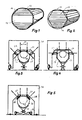
- FIG. 1 shows a body obtained by octagonally flattening a log, the circumferential line 10 of which is indicated. This is processed into boards 12 and a conical bar 14.
- FIG. 2 shows a body obtained by flattening round logs on eight sides, the circumferential line 10 of which is indicated, which is sawn into boards 12 of different thicknesses.
- FIG. 3 shows a processing unit according to the invention.
- Two axially parallel circular saws 24 and 25 are fastened to a chassis 20 which can be moved on wheels 22. As the double arrow 26 indicates, these circular saws can be adjusted towards and away from one another essentially transversely to the direction of travel of the processing unit.
- two sawing tools 28 and 29 are arranged, inclined at an obtuse angle to them.
- a round log 32 is arranged on height-adjustable supports 30 within the open cross-section of the chassis 20. As can be seen on the dashed line 34, which represents the circumference of the end of the round wood facing away from the viewer, it is mounted on the stands 30 in such a way that the upper surface of the round wood is aligned horizontally.
- the log 32 is also arranged at such a height that the axially parallel sawing tools are at the height at which the upper flattening or the upper surface is to be formed.
- the chassis 20 of the processing unit is moved once over the entire length of the round timber with running sawing tools.
- the log 32 is flattened simultaneously on three sides.
- the log is then turned through 180 ° about its longitudinal axis and placed on the stand 30, which are set to the desired height. Then the processing unit is again moved with running sawing tools over the entire length of the round timber 32, again 3 sides of the round timber 32 being flattened at the same time.
- FIG. 4 shows the processing unit of FIG. 3, which, however, is set to flatten the remaining two lateral forest edges.
- the two axially parallel sawing tools 24 and 25 are moved into their upper end position, in which they are arranged at a clear distance above the log.
- the two side sawing tools 28 and 29 are each placed vertically.
- removal tools 28 and 29 are to be moved toward or away from the long timber while the processing unit is being advanced, then removal tools 28 and 29 are preferably used as cutting tools.
- 24, 25, 28 and 29 generally refer to abrasive or flattening tools. So instead of circular saws or cutting tools, chainsaws or saws can also be used.
- the processing unit shown therein allows the round-sided flattening of a log in only three work passes.
- FIG. 1 Another embodiment of the invention is shown in FIG.
- two axially parallel sawing tools 24, 25 and two oblique removal tools 28 and 29 are mounted on a gate-shaped, fixed stand 36 of a processing unit.
- the round timber 32 is mounted on height-adjustable stands 34, which in turn can be moved on wheels 36.
- the log 32 is moved relative to the processing unit.
- the axially parallel sawing tools 24 and 25 are in turn mounted in a height-adjustable manner, and the lateral removal tools 28 and 29 are mounted so as to be displaceable both in their inclination and in their height position.
- FIG. 6 shows a stationary base frame 38, which is anchored to the floor and carries adjustable axially parallel sawing tools 24 and 25 and the lateral removal tools 28 and 29 on its concave upper side.
- Hydraulic rams 44 and an adjustable upper system 46 are provided in a carriage 40 which can be moved by means of wheels 42 running on rails.
- the log 32 is pressed upwards by means of the hydraulic ram 44 against the adjustable system 46 and held in this position while the carriage 40 moves the log 32 in the working direction, with the removal tools 24, 25, 28 and 29 the log 32 simultaneously on three sides flatten.
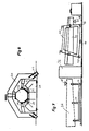
- FIG. 7 schematically shows a system for the continuous processing of the top and bottom sides as a further possible embodiment.
- the upper side is processed according to FIG. 5.
- the right section in FIG. 7 that is to say after passing through the processing unit 36, a luffing carriage 50 takes over the round timber according to the diagram in FIG. 6, the left and middle ones Rollers 53 and 54 rest on rails 58.
- the seesaw carriage 50 is tilted as shown in FIG. 7.
- the top of the log is parallel to the rail, as indicated by the triangle 60 in FIG.
- an outer pair of rollers 52 or 56 on the seesaw carriage 50 is designed to be height-adjustable.
Landscapes
- Life Sciences & Earth Sciences (AREA)
- Engineering & Computer Science (AREA)
- Mechanical Engineering (AREA)
- Wood Science & Technology (AREA)
- Forests & Forestry (AREA)
- Chemical And Physical Treatments For Wood And The Like (AREA)
- Milling, Drilling, And Turning Of Wood (AREA)
- Looms (AREA)
- Debarking, Splitting, And Disintegration Of Timber (AREA)
Priority Applications (7)
| Application Number | Priority Date | Filing Date | Title |
|---|---|---|---|
| DE8787105436T DE3780033D1 (de) | 1987-04-13 | 1987-04-13 | Verfahren und vorrichtung zum besaeumen von rundhoelzern. |
| EP87105436A EP0286701B1 (de) | 1987-04-13 | 1987-04-13 | Verfahren und Vorrichtung zum Besäumen von Rundhölzern |
| AT87105436T ATE77578T1 (de) | 1987-04-13 | 1987-04-13 | Verfahren und vorrichtung zum besaeumen von rundhoelzern. |
| PL1988271449A PL159869B1 (pl) | 1987-04-13 | 1988-03-26 | Sposób obróbki ze wszystkich stron klód i urzadzenie do obróbki ze wszystkich stron klód PL |
| US07/174,353 US4846237A (en) | 1987-04-13 | 1988-03-28 | Method and apparatus for sawing round wood trunks |
| CA000563322A CA1320896C (en) | 1987-04-13 | 1988-04-05 | Method and apparatus for sawing round wood trunks |
| CS882531A CS276899B6 (en) | 1987-04-13 | 1988-04-13 | Apparatus for logs edging |
Applications Claiming Priority (1)
| Application Number | Priority Date | Filing Date | Title |
|---|---|---|---|
| EP87105436A EP0286701B1 (de) | 1987-04-13 | 1987-04-13 | Verfahren und Vorrichtung zum Besäumen von Rundhölzern |
Publications (2)
| Publication Number | Publication Date |
|---|---|
| EP0286701A1 EP0286701A1 (de) | 1988-10-19 |
| EP0286701B1 true EP0286701B1 (de) | 1992-06-24 |
Family
ID=8196919
Family Applications (1)
| Application Number | Title | Priority Date | Filing Date |
|---|---|---|---|
| EP87105436A Expired - Lifetime EP0286701B1 (de) | 1987-04-13 | 1987-04-13 | Verfahren und Vorrichtung zum Besäumen von Rundhölzern |
Country Status (7)
| Country | Link |
|---|---|
| US (1) | US4846237A (pl) |
| EP (1) | EP0286701B1 (pl) |
| AT (1) | ATE77578T1 (pl) |
| CA (1) | CA1320896C (pl) |
| CS (1) | CS276899B6 (pl) |
| DE (1) | DE3780033D1 (pl) |
| PL (1) | PL159869B1 (pl) |
Cited By (1)
| Publication number | Priority date | Publication date | Assignee | Title |
|---|---|---|---|---|
| AT397224B (de) * | 1991-05-14 | 1994-02-25 | Wolf Systembau Gmbh & Co Kg | Verfahren und vorrichtung zum herstellen von vierkantern aus baumstämmen od. dgl. |
Families Citing this family (18)
| Publication number | Priority date | Publication date | Assignee | Title |
|---|---|---|---|---|
| SE505056C2 (sv) * | 1991-03-19 | 1997-06-16 | Martin Wiklund | Förfarande för sönderdelning av stockar |
| SE9103009L (sv) * | 1991-10-16 | 1993-04-17 | Lars Hammarstroem | Foerfarande foer reducering av en stock |
| AU652410B2 (en) * | 1992-01-24 | 1994-08-25 | Hexipine Pty Ltd | Milling assembly and method |
| CA2073356A1 (en) * | 1992-07-07 | 1994-01-08 | Hale Randle | Heart centered square timber production mechanism and method |
| US5806401A (en) * | 1994-01-04 | 1998-09-15 | Rajala; Edward | Satellite sawmill with adjustable saws and automatic sawbolt centering device |
| US5664611A (en) * | 1996-01-29 | 1997-09-09 | Mcdowell; Merle | Primary log breakout machine |
| US5934348A (en) * | 1996-02-02 | 1999-08-10 | Dietz; Hans | Method and apparatus for the fabrication of strands |
| EP0963822B1 (de) | 1998-06-10 | 2004-08-04 | Esterer WD GmbH & Co. | Vorrichtung und Verfahren zum Zerteilen von Baumstämmen |
| US5918653A (en) * | 1998-06-17 | 1999-07-06 | U. S. Natural Resources | Adjustable support for conveyor |
| US6176283B1 (en) | 1998-06-17 | 2001-01-23 | U.S. Natural Resources, Inc. | Adjustable support for conveyor |
| AT406131B (de) * | 1998-07-17 | 2000-02-25 | Wolf Systembau Gmbh & Co Kg | Verfahren und vorrichtung zum herstellen von acht- oder mehrseitigen kanthölzern |
| AT407233B (de) * | 1999-04-09 | 2001-01-25 | Johann Wolf | Vorrichtung zum erzeugen von vierkantbalken aus baumstämmen |
| DE102004051933A1 (de) * | 2004-10-25 | 2006-05-04 | Gebrüder Linck Maschinenfabrik "Gatterlinck" GmbH & Co KG | Vorrichtung und Verfahren zum Profilieren von Baumstämmen |
| CN103831884A (zh) * | 2012-11-22 | 2014-06-04 | 南京林业大学 | 一种原木精准制备正六棱柱体方法 |
| ITPI20130022A1 (it) * | 2013-03-29 | 2014-09-30 | Scuola Superiore Di Studi Universit Ari E Di Perfe | Dispositivo per la smussatura di travi. |
| CN106584632B (zh) * | 2014-11-05 | 2019-03-05 | 南京林业大学 | 一种正六棱柱毛坯材梳齿机的压紧系统 |
| CN104493904B (zh) * | 2014-12-24 | 2016-06-29 | 福建长汀县元创木工机械有限公司 | 龙门圆木断料锯及其使用方法 |
| CN104526783B (zh) * | 2014-12-24 | 2016-05-18 | 福建长汀县元创木工机械有限公司 | 圆木翻转、刨底取平面装置及其使用方法 |
Family Cites Families (13)
| Publication number | Priority date | Publication date | Assignee | Title |
|---|---|---|---|---|
| DE304676C (pl) * | ||||
| GB190411828A (en) * | 1904-05-24 | 1905-03-02 | Niels Georg Soerensen | Improved Manufacture of Boards from Round Timber. |
| US1340286A (en) * | 1918-12-23 | 1920-05-18 | Joseph A Neal | Twin circular resawing machine |
| FR78429E (fr) * | 1960-04-21 | 1962-07-20 | Linck Maschf & Eisen | Procédé et installation pour débiter du bois, de préférence des troncs d'arbresronds |
| US3388727A (en) * | 1965-07-09 | 1968-06-18 | Good Ko Ind Inc | Multiple-cut apparatus |
| US3457978A (en) * | 1966-11-07 | 1969-07-29 | Mo Och Domsjoe Ab | Method and apparatus for cutting logs into lumber and recovering the byproducts |
| US3552457A (en) * | 1968-05-29 | 1971-01-05 | Mac Millan Bloedel Ltd | Log break-down method and apparatus |
| US3648743A (en) * | 1969-01-23 | 1972-03-14 | Michele Fino | Equipment for longitudinally cutting tree logs |
| US3627005A (en) * | 1969-04-15 | 1971-12-14 | David L Morton | Machine for cutting peeler cores or logs into studs and chips |
| US4239069A (en) * | 1979-08-10 | 1980-12-16 | Zimmerman Edwin H | Automatic cant production machine |
| CH646366A5 (en) * | 1979-11-28 | 1984-11-30 | Wurster & Dietz Gmbh Co | Sawing machine and method of operating it |
| DE3415932A1 (de) * | 1984-04-28 | 1985-11-07 | Gebrüder Linck Maschinenfabrik und Eisengießerei "Gatterlinck", 7602 Oberkirch | Vorrichtung zur spanenden bearbeitung der seiten von holzstaemmen |
| AT390025B (de) * | 1985-11-13 | 1990-03-12 | Johann Wolf | Vorrichtung zum herstellen prismatischer oder pyramidenstumpffoermiger balken |
-
1987
- 1987-04-13 EP EP87105436A patent/EP0286701B1/de not_active Expired - Lifetime
- 1987-04-13 AT AT87105436T patent/ATE77578T1/de active
- 1987-04-13 DE DE8787105436T patent/DE3780033D1/de not_active Expired - Lifetime
-
1988
- 1988-03-26 PL PL1988271449A patent/PL159869B1/pl unknown
- 1988-03-28 US US07/174,353 patent/US4846237A/en not_active Expired - Fee Related
- 1988-04-05 CA CA000563322A patent/CA1320896C/en not_active Expired - Fee Related
- 1988-04-13 CS CS882531A patent/CS276899B6/cs unknown
Cited By (1)
| Publication number | Priority date | Publication date | Assignee | Title |
|---|---|---|---|---|
| AT397224B (de) * | 1991-05-14 | 1994-02-25 | Wolf Systembau Gmbh & Co Kg | Verfahren und vorrichtung zum herstellen von vierkantern aus baumstämmen od. dgl. |
Also Published As
| Publication number | Publication date |
|---|---|
| US4846237A (en) | 1989-07-11 |
| PL271449A1 (en) | 1989-01-23 |
| PL159869B1 (pl) | 1993-01-29 |
| CA1320896C (en) | 1993-08-03 |
| EP0286701A1 (de) | 1988-10-19 |
| CS276899B6 (en) | 1992-09-16 |
| DE3780033D1 (de) | 1992-07-30 |
| CS253188A3 (en) | 1992-03-18 |
| ATE77578T1 (de) | 1992-07-15 |
Similar Documents
| Publication | Publication Date | Title |
|---|---|---|
| EP0286701B1 (de) | Verfahren und Vorrichtung zum Besäumen von Rundhölzern | |
| DE3020917A1 (de) | Buntaufteilanlage fuer plattenartige werkstuecke | |
| DE3415332A1 (de) | Verfahren zum herstellen eines raeumwerkzeugs | |
| EP0217784B1 (de) | Verfahren und Vorrichtung zum Besäumen von Baumstämmen | |
| DE3702890C2 (pl) | ||
| AT390025B (de) | Vorrichtung zum herstellen prismatischer oder pyramidenstumpffoermiger balken | |
| LU82459A1 (de) | Verfahren und vorrichtung zum verarbeiten von rundholz zu schnittholz | |
| DE69711947T2 (de) | Verfahren und Vorrichtung zum spanenden Bearbeiten von Baumstämmen | |
| DE3020321A1 (de) | Verfahren und vorrichtung zur spanenden zerlegung von baumstaemmen in hauptware und seitenbretter | |
| DE3717731A1 (de) | Holzbearbeitungsmaschine | |
| DE2419938A1 (de) | Verfahren zum maschinellen herstellen von zapfen und schlitzen an hoelzern, insbesondere an sogenannten rahmenhoelzern fuer fensterrahmen, und maschine zur ausuebung dieses verfahrens | |
| AT390223B (de) | Vorschubeinrichtung fuer plattensaegen | |
| EP0744255A2 (de) | Vorrichtung zum Zerlegen von Baumstämmen in Holzerzeugnisse und Fräskopf für eine solche Vorrichtung | |
| DE4400600A1 (de) | Verfahren zum Zerlegen eines Baumstammes in allseitig bearbeitete Holzerzeugnisse | |
| DE29521324U1 (de) | Vorrichtung zum Schneiden | |
| EP0785051A1 (de) | Verfahren und Vorrichtung zum Einschneiden eines Baumstammes | |
| DE3915855C2 (pl) | ||
| DE1752117A1 (de) | Blechbearbeitungsmaschine | |
| DE69806140T2 (de) | Vorrichtung zum kaltschneiden von länglichen gegenständen entlang einer längsachse | |
| DE69502285T2 (de) | Ein verfahren zur längsbearbeitung von holzwerkstoffen und anordnung zur durchführung des verfahrens | |
| DE3410654A1 (de) | Pruefvorrichtung fuer rollfaehige schaefte | |
| EP0327139A2 (de) | Vorrichtung zum Herstellen von prismatischen oder pyramidenstumpfförmigen Balken | |
| EP1046480B1 (de) | Vorrichtung zum Zerlegen von Baumstämmen in einem Quartierabschnitt und zugehörige Sägestation | |
| DE3717756C2 (de) | Verfahren zum Auftrennen von krummen Rundhölzern in gebogene Bretter, Bohlen oder Kantholz | |
| DE532070C (de) | Maschine zum Zurichten von ebenen Druckplatten |
Legal Events
| Date | Code | Title | Description |
|---|---|---|---|
| PUAI | Public reference made under article 153(3) epc to a published international application that has entered the european phase |
Free format text: ORIGINAL CODE: 0009012 |
|
| AK | Designated contracting states |
Kind code of ref document: A1 Designated state(s): AT DE FR GB IT SE |
|
| 17P | Request for examination filed |
Effective date: 19881221 |
|
| 17Q | First examination report despatched |
Effective date: 19900212 |
|
| GRAA | (expected) grant |
Free format text: ORIGINAL CODE: 0009210 |
|
| AK | Designated contracting states |
Kind code of ref document: B1 Designated state(s): AT DE FR GB IT SE |
|
| REF | Corresponds to: |
Ref document number: 77578 Country of ref document: AT Date of ref document: 19920715 Kind code of ref document: T |
|
| ITF | It: translation for a ep patent filed | ||
| REF | Corresponds to: |
Ref document number: 3780033 Country of ref document: DE Date of ref document: 19920730 |
|
| GBT | Gb: translation of ep patent filed (gb section 77(6)(a)/1977) | ||
| ET | Fr: translation filed | ||
| PLBE | No opposition filed within time limit |
Free format text: ORIGINAL CODE: 0009261 |
|
| STAA | Information on the status of an ep patent application or granted ep patent |
Free format text: STATUS: NO OPPOSITION FILED WITHIN TIME LIMIT |
|
| PGFP | Annual fee paid to national office [announced via postgrant information from national office to epo] |
Ref country code: FR Payment date: 19930517 Year of fee payment: 7 |
|
| PGFP | Annual fee paid to national office [announced via postgrant information from national office to epo] |
Ref country code: SE Payment date: 19930526 Year of fee payment: 7 Ref country code: GB Payment date: 19930526 Year of fee payment: 7 Ref country code: AT Payment date: 19930526 Year of fee payment: 7 |
|
| 26N | No opposition filed | ||
| PGFP | Annual fee paid to national office [announced via postgrant information from national office to epo] |
Ref country code: DE Payment date: 19930622 Year of fee payment: 7 |
|
| PG25 | Lapsed in a contracting state [announced via postgrant information from national office to epo] |
Ref country code: GB Effective date: 19940413 Ref country code: AT Effective date: 19940413 |
|
| PG25 | Lapsed in a contracting state [announced via postgrant information from national office to epo] |
Ref country code: SE Effective date: 19940414 |
|
| GBPC | Gb: european patent ceased through non-payment of renewal fee |
Effective date: 19940413 |
|
| PG25 | Lapsed in a contracting state [announced via postgrant information from national office to epo] |
Ref country code: FR Effective date: 19941229 |
|
| PG25 | Lapsed in a contracting state [announced via postgrant information from national office to epo] |
Ref country code: DE Effective date: 19950103 |
|
| EUG | Se: european patent has lapsed |
Ref document number: 87105436.7 Effective date: 19941110 |
|
| REG | Reference to a national code |
Ref country code: FR Ref legal event code: ST |
|
| PG25 | Lapsed in a contracting state [announced via postgrant information from national office to epo] |
Ref country code: IT Free format text: LAPSE BECAUSE OF NON-PAYMENT OF DUE FEES;WARNING: LAPSES OF ITALIAN PATENTS WITH EFFECTIVE DATE BEFORE 2007 MAY HAVE OCCURRED AT ANY TIME BEFORE 2007. THE CORRECT EFFECTIVE DATE MAY BE DIFFERENT FROM THE ONE RECORDED. Effective date: 20050413 |