EP0286050B1 - Seitenübertragungsvorrichtung für Flachstrickmaschinen - Google Patents
Seitenübertragungsvorrichtung für Flachstrickmaschinen Download PDFInfo
- Publication number
- EP0286050B1 EP0286050B1 EP88105390A EP88105390A EP0286050B1 EP 0286050 B1 EP0286050 B1 EP 0286050B1 EP 88105390 A EP88105390 A EP 88105390A EP 88105390 A EP88105390 A EP 88105390A EP 0286050 B1 EP0286050 B1 EP 0286050B1
- Authority
- EP
- European Patent Office
- Prior art keywords
- fingers
- needles
- transfer
- loops
- machine
- Prior art date
- Legal status (The legal status is an assumption and is not a legal conclusion. Google has not performed a legal analysis and makes no representation as to the accuracy of the status listed.)
- Expired - Lifetime
Links
Images


Classifications
-
- D—TEXTILES; PAPER
- D04—BRAIDING; LACE-MAKING; KNITTING; TRIMMINGS; NON-WOVEN FABRICS
- D04B—KNITTING
- D04B7/00—Flat-bed knitting machines with independently-movable needles
- D04B7/10—Flat-bed knitting machines with independently-movable needles with provision for narrowing or widening to produce fully-fashioned goods
-
- D—TEXTILES; PAPER
- D04—BRAIDING; LACE-MAKING; KNITTING; TRIMMINGS; NON-WOVEN FABRICS
- D04B—KNITTING
- D04B15/00—Details of, or auxiliary devices incorporated in, weft knitting machines, restricted to machines of this kind
- D04B15/02—Loop-transfer points
-
- D—TEXTILES; PAPER
- D04—BRAIDING; LACE-MAKING; KNITTING; TRIMMINGS; NON-WOVEN FABRICS
- D04B—KNITTING
- D04B15/00—Details of, or auxiliary devices incorporated in, weft knitting machines, restricted to machines of this kind
- D04B15/32—Cam systems or assemblies for operating knitting instruments
- D04B15/36—Cam systems or assemblies for operating knitting instruments for flat-bed knitting machines
- D04B15/362—Cam systems or assemblies for operating knitting instruments for flat-bed knitting machines with two needle beds in V-formation
- D04B15/365—Cam systems or assemblies for operating knitting instruments for flat-bed knitting machines with two needle beds in V-formation with provision for loop transfer from one needle bed to the other
Definitions
- This invention relates to a side-transfer device for flat knitting machines, which is particularly adapted to effect the automatic narrowing of the knitted fabric being manufactured, no matter whether it is of the type involving one or both the needle beds of the machine.
- the invention relates also to a new method for operating the automatic narrowing of the knitted fabric by utilizing the new side-transfer device.
- Document EP-A-0 103 033 discloses a side-transfer device for flat knitting machines, which comprises, parallelly and above the needle bed opposite to the needle bed involved in operation, an auxiliary and composite smaller needle bed containing independently movable transfer fingers equally spaced apart with the same spacing as the needles of said needle beds and in such a number as to serve all the needles of the needle bed which may be involved in the side transfer, said auxiliary smaller needle bed including two semi-needle beds which are identical, in line with each other and sufficiently spaced as to be able to move towards and away from each other during the transfer step, each semi-needle bed being mounted so as to be longitudinally slidable, through a respective slide, on a single guide, said guide being pivotable about its longitudinal axis, and means being provided whereby, under command, this pivotal movement is effected to raise and lower said semi-needle beds.
- this side-transfer device is equipped with transfer fingers comprising a flat spring and a single indentation.
- a side-transfer device of the above disclosed type which is characterized by the fact that:
- the side-transfer device is further characterized by the fact that the means effecting the pivotal movement of the device comprise at least a respective lever which is mounted so as to be freely pivotable on the end portions of the longitudinal axis of said device, and comprises respective electro-magnets which, under command, will lock said levers to said shaft, said levers being provided at their ends with a roller arranged on the path of travel of a cam associated with the machine carriage, the arrangement being such that when said auxiliary smaller needle bed is to be raised, said levers are locked on the shaft mounting them, whereas in the contrary case said levers are freely pivotable on said shaft, said cam being so shaped as to act on said levers at the end of either the rightwards and the leftwards stroke of the machine carriage.
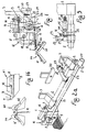
- FA and FP indicate the front and the rear needle beds, respectively, of a flat knitting machine, which are provided, preferably, with transfer needles A1 and A2 which, according to a conventional technique, permit to carry out a narrowing operation by acting only on the needles of either one of the two needle beds (for example, on the needles of the needle bed FA) regardless of whether the fabric being knitted concerns one or both said needle beds.
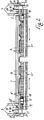
- the transfer device is arranged, for example, above the needle bed FP and comprises a guide bed 1 which is parallel to said needle bed, it has substantially the same length as said needle bed and is fulcrumed, at least at the ends thereof, at 2, on supports 3 which, in turn, are secured to the frame of the machine.
- the fulcrum 2 is parallel to 1 and to the needle bed FA.
- the bed 5-5 ⁇ of the smaller needle beds FT-FT ⁇ is half the length of the needle bed FA of the machine and is formed with transverse equally spaced apart grooves having the same spacing or pitch as the needles of the needle beds FA-FP and slidably supporting therein the narrowing fingers 7, which are formed with a respective butt cooperatively engageable by a small carriage 8 to be discussed below, provided with cams or triangles which may be either activated or disactivated in a conventional manner in order to selectively displace said fingers longitudinally as discussed below.
- said fingers 7 When the transfer device is in its rest position as shown in fig. 1, said fingers 7 are completely retracted in their guide seats, so as to avoid interfering with the movement of the needles in the machine needle beds. However, said fingers 7 are already oriented as required to carry out the first steps of the operating cycle pertaining to them (see below).
- the fingers 7 present a substantially known shape and comprise a front indentation 9 and a rear indentation 10 deeper that the former and registering with a slot which is formed at one side of said finger, in a flat spring 11 secured in a conventional manner at its rear end to one side of said finger.
- the carriage 8 is supported by a structure 12 which, through grooved wheels 13, moves on a guide 14 which is secured longitudinally to the guide 1 with the interposition of spacer 15.
- a fork-like member 16 is provided on the top and intermediate section of the structure 12 for the mechanical connection with the carriage of the machine through means permitting the device to pivot freely about the fulcrum 2.
- each slide 4-4 ⁇ has secured thereto a support 17-17 ⁇ carrying a nut member co-operating with a screw member 18-18 ⁇ which is connected through a shaft 19-19 ⁇ to a reversible motor unit 20-20 ⁇ which, in turn, is rotated by a support 21-21 ⁇ so arranged as to be pivotable on the fulcrum 2.
- pivotably and normally mounted on the ends of the fulcrum shaft 2 are respective levers 22-22 ⁇ each of which is urged upwards by a resilient means 31 and is formed with a hole 23 parallel to said shaft 2 in one side thereof.
- the hole 23 is aligned with or slightly above a lock bolt 24 which is movable in a hole 25 formed in a body 26 keyed to the shaft 2 and mounting an electro-magnet 27 whose movable member is connected to said bolt 24 and to an opposing spring 28 which usually keeps said bolt in a retracted position within its seat 25.
- the lock bolt 24 is sized and arranged so that when the electro-magnet 27 is energized and the lever 22 is pivoted downwards, said lock bolt engages the hole 23 and locks said lever 22 to the shaft 2, whereby the smaller needle beds FT-FT ⁇ are pivoted about the shaft 2 (see below) and are raised.
- a similar servo-control 27 ⁇ is provided to lock, if desired, also the lever 22 ⁇ to the shaft 2.
- each lever 22-22 ⁇ mounts at an end thereof an idle roller 29-29 ⁇ arranged on the rectilinear path of travel of a rectilinear cam 30 associated with the main frame of the machine and shaped at both ends thereof as shown in fig. 2a, so as to operatively act on the lever 22 and on the lever 22 ⁇ during the rightward and leftward displacements of the machine carriage.
- the device disclosed above operates as follows: At the beginning of each transfer cycle, the auxiliary smaller needle beds FT-FT ⁇ are arranged with their inner ends at the maximum distance from each other if, obviously, the transfer is supposed to effect a decrease in the operating needles of the machine.
- the cam 30 engages, for example, the roller 29 of the lever 22 and the latter is locked to the shaft 2 due to the programmed action of the electro-magnet 27.
- the device is pivoted about the shaft 2 and causes the lifting movement of said auxiliary smaller needle beds FT-FT ⁇ to such an extent whereby the fingers 7 loaded with the loops B will disengage from the top portion of the machine needle beds.
- the drive units 20-20 ⁇ are now activated and move the smaller needle beds FT-FT ⁇ longitudinally towards the centre of the machine, each by the extent required by the transfer step.
- the machine carriage On completion of the transfer, the machine carriage starts the next operative stroke and the cam 30 disengages from the roller 29, so that the auxiliary smaller needle beds FT-FT ⁇ are returned to their initial lower position.
- the needles A ⁇ are then lowered again, while at due time the fingers 7 are retracted into the respective auxiliary smaller needle beds FT-FT ⁇ , as shown in the sequence of figures 15 and 16.
- the loops B remain on the needles A ⁇ , which in their descent will be closed due to the co-operation between their latches with conventional means.
- the smaller needle beds FT-FT ⁇ are moved again to the most spaced apart position and are ready for repeating a new operative cycle.
Landscapes
- Engineering & Computer Science (AREA)
- Textile Engineering (AREA)
- Knitting Machines (AREA)
Claims (3)
- Seitenübertragungsvorrichtung für Flachstrickmaschinen des Typs mit einem parallel und oberhalb des Nadelbetts (FP), welches dem am Arbeitsvorgang beteiligten Nadelbett (FA) gegenüberliegt, angeordneten, zusätzlichen, und zusammengesetzten, kleineren Nadelbett (FT-FT'), das unabhängig voneinander bewegbare Übertragungsfinger (7) enthält, die denselben gleichmäßigen Abstand haben wie die Nadeln (A1, A2) der Nadelbetten und in solcher Anzahl vorhanden sind, daß sie allen Nadeln (A, A') des Nadelbetts dienen, die an der Seitenübertragung beteiligt sind, wobei das zusätzliche kleinere Nadelbett zwei identische Halb-Nadelbetten (FT, FT') aufweist, die miteinander fluchten und genügend Abstand haben, um während des Übertragungsvorgangs zueinander hin und voneinander weg bewegbar zu sein, und deren jedes jeweil durch einen Schlitten (4-4') längsverschieblich auf einer gemeinsamen Führung (1) gelagert ist, welche um ihre Längsachse schwenkbar ist, und Mittel (22, 27, 30) vorgesehen sind, durch die diese Schwenkbewegung gesteuert ausführbar ist, um die Halb-Nadelbetten (FT, FT') zu heben und zu senken,
dadurch gekennzeichnet, daßa) die unabhängig bewegbaren Finger (7) eine vordere Vertiefung (9) und eine hintere Vertiefung (10), die tiefer ist als die vordere Vertiefung (9) und mit einer Vertiefung in einer flachen, mit ihrem hinteren Ende an einer Seite der Finger (7) befestigten Feder (11) fluchtet, aufweisen und durch einen einzigen, mechanisch mit dem Maschinenwagen verbundenen Hilfswagen (8) steuerbar sind;b) die Führung (1) auch die Führung (14) für den Hilfswagen trägt; undc) jeder Schlitten (4, 4') zur Längsbewegung entweder nach rechts oder nach links mit einer Servosteuerung (17, 18, 19, 20, 17', 18', 19', 20') verbunden ist. - Vorrichtung nach Anspruch 1, dadurch gekennzeichnet, daß die Mittel zur Ausführung der Schwenkbewegung der Vorrichtung jeweils wenigstens einen Hebel (22-22'), der frei drehbar auf den Endbereichen der sich in Längsrichtung erstreckenden Drehachse (2) der Vorrichtung gelagert ist, sowie zugeordnete Elektromagnete (27-27' ) aufweisen, welche, gesteuert, die Hebel an der Welle festlegen, die an ihren Enden mit einer Rolle (29-29') versehen sind, welche in der Bewegungsbahn eines mit dem Maschinenwagen verbundenen Nockens (30) liegt, wobei die Anordnung so getroffen ist, daß dann, wenn das zusätzliche, kleinere Nadelbett angehoben werden soll, die Hebel auf der sie tragenden Welle festgelegt werden, während andernfalls die Hebel auf der Welle frei drehbar sind, und wobei der Nocken (30) so ausgebildet ist, daß er am Ende entweder des rechtsgerichteten oder des linksgerichteten Hubs des Maschinenwagens auf die Hebel wirkt.
- Verfahren zur Seitenübertragung von Maschinen zur Durchführung der automatischen Verdichtung der auf einer Flachstrickmaschine nach Anspruch 1 hergestellten Strickware mit folgenden in Kombination auszuführenden Arbeitsschritten:a) die unabhängig bewegbaren, an der Seitenübertragung beteiligten Übertragungsfinger werden ausgefahren, und ihre Spitzen dringen in die zu übertragenden Maschen (B) ein, die durch die zugeordneten Übertragungsnadeln (A) der Maschine in geeigneter Weise angehoben und positioniert worden sind;b) die die Maschen tragenden Finger werden extrem ausgefahren, so daß die Maschen in Eingriff mit der hinteren Vertiefung der Finger kommen, wonach die Finger in die vorhergehende Stellung zurückgezogen werden;c) die die Übertragungsfinger enthaltenden Halb-Nadelbetten werden von den Maschinennadelbetten abgehoben, anschließend in dem für die Übertragung erforderlichen Ausmaß in Längsrichtung verschoben und dann wieder in die vorhergehende Stellung abgesenkt;d) die zur Übernahme der Maschen bestimmten Maschinennadeln werden angehoben;e) die Übertragungsfinger werden in ihre Ruhestellung zurückgezogen, während die Nadeln unter Mitnahme der Maschen (B) abgesenkt und durch Zusammenwirken ihrer Zungen mit herkömmlichen Mitteln geschlossen werden, wobei die Anordnung so getroffen ist, daß die Halb-Nadelbetten (FT-FT') vor Beginn eines neuen Zyklus durch eine Längsbewegung, die der zuvor bei dem aktiven Arbeitsschritt ausgeführten Längsbewegung entgegengerichtet ist, automatisch in ihre Anfangsstellung zurückkehrendadurch gekennzeichnet, daß vor dem Arbeitsschritt b), während die Maschinennadeln wieder abgesenkt werden, die die Maschen tragenden Finger zunächst ein kurzes Stück zurückgezogen und dann wieder ausgefahren werden, so daß die Maschen mit den Zungen der Nadeln zusammenwirken, um sie zu schließen, und während des Arbeitsschritts d) die maschentragenden Finger extrem ausgefahren, dann zurückgezogen und danach wieder ausgefahren werden, in der Weise, daß die Zungen der Nadeln während der vorbestimmten Relativbewegung zwischen dem System der Finger mit zugehörigen seitlichen Federn und den in die von den Fingern gehaltene Maschen eindringenden Nadeln eingeklemmt und geöffnet werden.
Applications Claiming Priority (2)
| Application Number | Priority Date | Filing Date | Title |
|---|---|---|---|
| IT1245887 | 1987-04-10 | ||
| IT8712458A IT1208272B (it) | 1987-04-10 | 1987-04-10 | Apparato di trasporto laterale per le macchine rettilinee da maglieria |
Publications (3)
| Publication Number | Publication Date |
|---|---|
| EP0286050A2 EP0286050A2 (de) | 1988-10-12 |
| EP0286050A3 EP0286050A3 (de) | 1991-01-30 |
| EP0286050B1 true EP0286050B1 (de) | 1993-11-24 |
Family
ID=11140400
Family Applications (1)
| Application Number | Title | Priority Date | Filing Date |
|---|---|---|---|
| EP88105390A Expired - Lifetime EP0286050B1 (de) | 1987-04-10 | 1988-04-05 | Seitenübertragungsvorrichtung für Flachstrickmaschinen |
Country Status (5)
| Country | Link |
|---|---|
| EP (1) | EP0286050B1 (de) |
| JP (1) | JPS63256752A (de) |
| DE (1) | DE3885783T2 (de) |
| ES (1) | ES2048168T3 (de) |
| IT (1) | IT1208272B (de) |
Families Citing this family (10)
| Publication number | Priority date | Publication date | Assignee | Title |
|---|---|---|---|---|
| JP2794144B2 (ja) * | 1992-10-22 | 1998-09-03 | 株式会社島精機製作所 | 目移し装置を有する横編機 |
| JP2604677B2 (ja) * | 1992-12-17 | 1997-04-30 | 株式会社島精機製作所 | 横編機におけるトランスファージャック |
| JP3192510B2 (ja) * | 1992-12-22 | 2001-07-30 | 株式会社島精機製作所 | 横編機における交差柄編成方法及び交差柄編成装置 |
| DE4437583C1 (de) * | 1994-10-20 | 1996-03-21 | Schieber Universal Maschf | Flachstrickmaschine |
| JP3408735B2 (ja) * | 1997-12-19 | 2003-05-19 | 株式会社島精機製作所 | トランスファージャック目移し機構を備えた横編機 |
| JP3226873B2 (ja) * | 1998-05-07 | 2001-11-05 | 株式会社島精機製作所 | 目移し機構を備えた横編機およびその目移し方法 |
| DE19954477A1 (de) * | 1999-11-12 | 2001-06-07 | Stoll & Co H | Verfahren und Vorrichtung zum Umhängen von Maschen auf einer Strickmaschine |
| DE10019987A1 (de) * | 2000-04-22 | 2001-10-25 | Stoll & Co H | Verfahren zur Herstellung von Gestricken mit mehreren Strickebenen |
| CN107572206B (zh) * | 2017-10-13 | 2023-05-26 | 江苏金龙科技股份有限公司 | 电脑针织横编机的机头转运装置 |
| CN121285665A (zh) | 2023-06-07 | 2026-01-06 | 株式会社岛精机制作所 | 具备移圈底脚片的横机及移圈底脚片 |
Family Cites Families (5)
| Publication number | Priority date | Publication date | Assignee | Title |
|---|---|---|---|---|
| DE1149848B (de) * | 1958-03-15 | 1963-06-06 | Schieber Universal Maschf | Flachstrickmaschine mit einer Vorrichtung zum UEbertragen von Maschen |
| CH373849A (fr) * | 1961-08-18 | 1963-12-15 | Dubied & Cie Sa E | Procédé de diminution de pièces d'articles tricotées en mailles unies, côtes ou autres genres de mailles, et machine à tricoter rectiligne pour la mise en oeuvre de ce procédé |
| BE793454A (fr) * | 1972-07-20 | 1973-04-16 | Abril Cullell | Perfectionnements apportes aux mecanismes de transfert lateral automatique des mailles dans les machines a tricoter |
| DE3111193A1 (de) * | 1981-03-21 | 1982-11-11 | Hobby-Hand GmbH, 5000 Köln | Vorrichtung zum umhaengen von maschen eines strickzeugs |
| EP0103033A1 (de) * | 1982-09-09 | 1984-03-21 | COMET MARTINELLI S.r.l. | Vorrichtung zum Umhängen von Nadelmaschen in Flachstrick-maschinen |
-
1987
- 1987-04-10 IT IT8712458A patent/IT1208272B/it active
- 1987-11-25 JP JP62295400A patent/JPS63256752A/ja active Pending
-
1988
- 1988-04-05 EP EP88105390A patent/EP0286050B1/de not_active Expired - Lifetime
- 1988-04-05 DE DE3885783T patent/DE3885783T2/de not_active Expired - Fee Related
- 1988-04-05 ES ES88105390T patent/ES2048168T3/es not_active Expired - Lifetime
Also Published As
| Publication number | Publication date |
|---|---|
| EP0286050A2 (de) | 1988-10-12 |
| IT1208272B (it) | 1989-06-12 |
| ES2048168T3 (es) | 1994-03-16 |
| EP0286050A3 (de) | 1991-01-30 |
| DE3885783D1 (de) | 1994-01-05 |
| IT8712458A0 (it) | 1987-04-10 |
| DE3885783T2 (de) | 1994-06-30 |
| JPS63256752A (ja) | 1988-10-24 |
Similar Documents
| Publication | Publication Date | Title |
|---|---|---|
| EP0286050A2 (de) | Seitenübertragungsvorrichtung für Flachstrickmaschinen | |
| US7207194B2 (en) | Weft knitting machine with movable yarn guide member | |
| EP0435690B1 (de) | Platinenvorrichtung für Flachstrickmaschinen | |
| US4188815A (en) | Die changing apparatus for a bending brake | |
| EP0472341B1 (de) | Flachstrickmaschine mit Schwingplatinen und Druckleisten | |
| US4100767A (en) | Knitting machine pattern mechanism | |
| JPH0366415B2 (de) | ||
| US5042275A (en) | Restoring device for a needle selecting apparatus of a circular knitting machine | |
| US4004437A (en) | Flat knitting machine | |
| US5212968A (en) | Presser controller of a carriage in a flat knitting machine | |
| GB2029867A (en) | Single needle selection device for flat knitting machines | |
| US2162121A (en) | Automatic welt turning mechanism | |
| JP3457161B2 (ja) | 横編機における編地引下げ装置 | |
| US4312196A (en) | Guidebar shogging guide apparatus for warp knitting machines | |
| US4414826A (en) | Summation drive for controlling shogging in a warp knitting machine | |
| US3608335A (en) | Device for automatic narrowing on both needle-beds of flat knitting machines | |
| EP0805885B1 (de) | Vorrichtung zum vertikalen spannen vom gestrick an einer automatischen strickmaschine, insbesondere an einer flachstrickmaschine | |
| US5469717A (en) | Method for knitting a crossing pattern and an apparatus for knitting a crossing pattern in flat knitting machine | |
| US4283927A (en) | Hand-operated knitting machine with loop transfer functions | |
| US3243976A (en) | Production of rib welts for knitted garments | |
| US5056338A (en) | Yarn positioning controller for flat-bed knitting machines | |
| GB2085116A (en) | Displacement and detent mechanisms for a multi-head embroidery machine | |
| US3656322A (en) | Straight bar knitting machines | |
| US4576288A (en) | Card sorting machine | |
| JPH0610246A (ja) | 可動シンカーの揺動制御装置 |
Legal Events
| Date | Code | Title | Description |
|---|---|---|---|
| PUAI | Public reference made under article 153(3) epc to a published international application that has entered the european phase |
Free format text: ORIGINAL CODE: 0009012 |
|
| AK | Designated contracting states |
Kind code of ref document: A2 Designated state(s): CH DE ES FR GB LI |
|
| PUAL | Search report despatched |
Free format text: ORIGINAL CODE: 0009013 |
|
| AK | Designated contracting states |
Kind code of ref document: A3 Designated state(s): CH DE ES FR GB LI |
|
| 17P | Request for examination filed |
Effective date: 19910531 |
|
| 17Q | First examination report despatched |
Effective date: 19920427 |
|
| GRAA | (expected) grant |
Free format text: ORIGINAL CODE: 0009210 |
|
| AK | Designated contracting states |
Kind code of ref document: B1 Designated state(s): CH DE ES FR GB LI |
|
| REF | Corresponds to: |
Ref document number: 3885783 Country of ref document: DE Date of ref document: 19940105 |
|
| REG | Reference to a national code |
Ref country code: ES Ref legal event code: FG2A Ref document number: 2048168 Country of ref document: ES Kind code of ref document: T3 |
|
| ET | Fr: translation filed | ||
| PLBE | No opposition filed within time limit |
Free format text: ORIGINAL CODE: 0009261 |
|
| 26N | No opposition filed | ||
| PGFP | Annual fee paid to national office [announced via postgrant information from national office to epo] |
Ref country code: GB Payment date: 19960924 Year of fee payment: 9 |
|
| PGFP | Annual fee paid to national office [announced via postgrant information from national office to epo] |
Ref country code: FR Payment date: 19960930 Year of fee payment: 9 |
|
| PGFP | Annual fee paid to national office [announced via postgrant information from national office to epo] |
Ref country code: CH Payment date: 19961002 Year of fee payment: 9 |
|
| PGFP | Annual fee paid to national office [announced via postgrant information from national office to epo] |
Ref country code: ES Payment date: 19961003 Year of fee payment: 9 |
|
| PGFP | Annual fee paid to national office [announced via postgrant information from national office to epo] |
Ref country code: DE Payment date: 19961023 Year of fee payment: 9 |
|
| PG25 | Lapsed in a contracting state [announced via postgrant information from national office to epo] |
Ref country code: GB Effective date: 19970405 |
|
| PG25 | Lapsed in a contracting state [announced via postgrant information from national office to epo] |
Ref country code: ES Free format text: LAPSE BECAUSE OF NON-PAYMENT OF DUE FEES Effective date: 19970407 |
|
| PG25 | Lapsed in a contracting state [announced via postgrant information from national office to epo] |
Ref country code: LI Free format text: LAPSE BECAUSE OF NON-PAYMENT OF DUE FEES Effective date: 19970430 Ref country code: CH Free format text: LAPSE BECAUSE OF NON-PAYMENT OF DUE FEES Effective date: 19970430 |
|
| GBPC | Gb: european patent ceased through non-payment of renewal fee |
Effective date: 19970405 |
|
| REG | Reference to a national code |
Ref country code: CH Ref legal event code: PL |
|
| PG25 | Lapsed in a contracting state [announced via postgrant information from national office to epo] |
Ref country code: FR Free format text: LAPSE BECAUSE OF NON-PAYMENT OF DUE FEES Effective date: 19971231 |
|
| PG25 | Lapsed in a contracting state [announced via postgrant information from national office to epo] |
Ref country code: DE Free format text: LAPSE BECAUSE OF NON-PAYMENT OF DUE FEES Effective date: 19980101 |
|
| REG | Reference to a national code |
Ref country code: FR Ref legal event code: ST |
|
| REG | Reference to a national code |
Ref country code: ES Ref legal event code: FD2A Effective date: 19990503 |