EP0285001B1 - Gripper loom - Google Patents
Gripper loom Download PDFInfo
- Publication number
- EP0285001B1 EP0285001B1 EP88104717A EP88104717A EP0285001B1 EP 0285001 B1 EP0285001 B1 EP 0285001B1 EP 88104717 A EP88104717 A EP 88104717A EP 88104717 A EP88104717 A EP 88104717A EP 0285001 B1 EP0285001 B1 EP 0285001B1
- Authority
- EP
- European Patent Office
- Prior art keywords
- gripper
- weaving machine
- guide
- machine according
- driving wheel
- Prior art date
- Legal status (The legal status is an assumption and is not a legal conclusion. Google has not performed a legal analysis and makes no representation as to the accuracy of the status listed.)
- Expired - Lifetime
Links
Images


Classifications
-
- D—TEXTILES; PAPER
- D03—WEAVING
- D03D—WOVEN FABRICS; METHODS OF WEAVING; LOOMS
- D03D47/00—Looms in which bulk supply of weft does not pass through shed, e.g. shuttleless looms, gripper shuttle looms, dummy shuttle looms
- D03D47/27—Drive or guide mechanisms for weft inserting
- D03D47/275—Drive mechanisms
- D03D47/276—Details or arrangement of sprocket wheels
-
- D—TEXTILES; PAPER
- D03—WEAVING
- D03D—WOVEN FABRICS; METHODS OF WEAVING; LOOMS
- D03D47/00—Looms in which bulk supply of weft does not pass through shed, e.g. shuttleless looms, gripper shuttle looms, dummy shuttle looms
- D03D47/27—Drive or guide mechanisms for weft inserting
- D03D47/271—Rapiers
- D03D47/272—Rapier bands
-
- D—TEXTILES; PAPER
- D03—WEAVING
- D03D—WOVEN FABRICS; METHODS OF WEAVING; LOOMS
- D03D47/00—Looms in which bulk supply of weft does not pass through shed, e.g. shuttleless looms, gripper shuttle looms, dummy shuttle looms
- D03D47/27—Drive or guide mechanisms for weft inserting
- D03D47/277—Guide mechanisms
Definitions
- the invention relates to a rapier weaving machine according to the preamble of claim 1.
- Rapier looms of the type mentioned are known several times.
- EP-A-0 126 497 describes such a rapier weaving machine in which the entry belt engages with the drive wheel over part of the circumference, with a block-shaped guide member at the beginning and at the end of the engagement, the entry belt on the circumference of the drive wheel holds. The end of the belt facing away from the gripper head is guided in a guide channel. It is very disadvantageous that the block-shaped guide elements are exposed to a great deal of heating and great wear due to the friction, which has a disadvantageous effect on the working accuracy and the service life.
- Rapier weaving machines are also known which work with non-perforated entry belts.
- a rapier weaving machine is known from CH-A-652 764, in which the end of the belt facing away from the rapier head is firmly connected to a drive wheel, an entry belt being used which is not perforated, so that the force is introduced via the end of the belt and that One or more layers of tape can be wound onto the drive wheel.
- the rapier weaving machine has resilient devices which are arranged in the movement end region of an oscillating member of the drive device for the entry belt in such a way that the kinetic energy of the oscillating member is absorbed and stored at the end of the oscillating movement of a working stroke of the entry belt on the resilient device in order to deliver the stored energy back to the oscillating link at the beginning of the oscillating movement in the opposite direction, ie at the next working stroke.
- the energy-storing device interferes with the control of the weaving machine when the drive conditions change.
- the object of the invention is to design a rapier weaving machine of the type mentioned at the outset in such a way that an increase in speed, for example to 1000 rpm. is possible and that a simple guiding of the entry belt is still guaranteed, which is subject to only slight wear and tear and requires only low driving forces and absorbs the centrifugal forces.
- the entry belt is perforated and driven by a toothed drive wheel in the circumferential direction, so that the introduction of force is practically given or received in the direction of movement of the gripper head and that the end of the belt facing away from the gripper head is fastened to a rotatable guide device of larger diameter connected downstream of the drive wheel , the drive wheel can be made particularly small and thus low in mass. Since the downstream guiding device does not have to cope with any driving forces, it can be relatively large and yet particularly light and therefore also low in mass, and the frictional forces required for guiding channels are also eliminated, which not only benefits the protection of the entry belt, but also the lifting of the entry belt from Circumference of the driving wheel prevented.
- the guide device for the belt end of the entry belt facing away from the gripper head can have an additional guide wheel according to claim 2. This can either be driven by the moving entry belt, but the guide wheel is preferably coupled to the drive wheel in terms of drive. The inertia forces can be further reduced if the guide device is designed according to claim 3.
- the guide device is arranged independently of the driving wheel, a further guide member is recommended.
- the guide member which is assigned to the drive wheel on the side of the gripper head, can be designed as a sliding guide according to claim 6.
- an embodiment according to claim 7 is more advantageous, as a result of which the friction between the entry belt and the guide wheel is eliminated.
- An improvement in the drive between the guide wheel and the entry belt can be achieved by driving coupling of the guide wheel to the drive wheel, the guide wheel then also being able to serve to support the drive.
- These properties are further improved by an embodiment of the guide wheel according to claim 8.
- the guide wheel can cooperate with the perforation of the entry belt, which is intended for engagement with the drive wheel.
- an embodiment according to claim 9 is more advantageous, since then there is a more subtle interaction between the guide wheel and the entry belt.
- the management properties of the management body can be improved by a configuration according to claim 10 and / or 11.
- the compressed air can simultaneously press the entry belt against a drive wheel, which counteracts the centrifugal force of the driven entry belt and thus ensures a secure hold of the entry belt on the drive wheel.
- the sliding guide can be limited to the area facing the gripper head, at which the entry belt leaves the driving wheel.
- An embodiment according to claim 19 is also advantageous, as a result of which a secure hold of the entry belt on the drive wheel is ensured. Since a friction-reducing air cushion is formed by the compressed air, such a guide element can advantageously be arranged along the entire area on which the entry belt rests on the drive wheel. This ensures a secure hold of the entry belt on the drive wheel, the compressed air preferably being able to be set such that the entry belt is in contact with the drive wheel despite the centrifugal force.
- An embodiment according to claim 22 is also particularly advantageous, as a result of which the guidance of the rapier head and the entry belt on the reed is improved.
- an embodiment according to claim 23 is advantageous.
- the drive wheel 20 contains teeth 22 distributed around its circumference, which engage in holes in the perforated, flexible entry belt 14, as shown in detail in FIG.
- Such an entry belt can be designed, for example, according to FIGS. 6 and 10, as will be described in more detail below.
- the drive wheel 20 is assigned a guide member 24, which is designed as a sliding guide or, as shown, as a guide wheel 26, which is also provided with teeth 28 on its circumference.
- the guide wheel 26 engages that area of the entry belt 14 which is assigned to the gripper head 10 or 12 and ensures that Entry belt 14 is in close engagement with the drive wheel 20 and does not lift off during the drive.
- the teeth 28 of the guide wheel 26 can have the same size as the teeth 22 of the drive wheel 20 and engage in the same holes in which the teeth 22 of the drive wheel 20 also engage, so that, for example, an entry belt 14a according to FIG Perforation 30 with holes 32 of the same size.
- the guide wheel 26 has teeth 28 which are smaller than the teeth 22 of the drive wheel 20 and an entry belt 14b is required for this, as shown in FIG. 10.
- Such an input belt has a perforation 34 with a first row 35 with holes 36, which are intended for the teeth 22 of the drive wheel 20, and a second row 38 with holes 40, the size and spacing of which can be smaller than that of the holes 36 of the first Row 34, and which are intended to engage the teeth 28 of the guide wheel 26.
- both weft insertion devices 6, 8 are configured identically and their gripper heads 10, 12 each cover half the width of the shed 4 in their working stroke.
- the two weft insertion devices it is also entirely possible for the two weft insertion devices to have different working strokes, so that the transfer area follows can be shifted left or right in the shed.
- the movement sequences do not take place synchronously with one another, but instead out of phase, one of the gripper heads for example reaching the transfer area 46 in front of the other.
- the weft thread insertion devices in such a way that, for example, the looper head 10 already executes the retraction movement and is caught in the looper head 12.
- the weft insertion devices are designed differently and work according to a different principle, so that, for example, the right weft insertion device 8 of FIG. 1 can also be designed in accordance with CH-A-671 412.
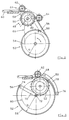
- FIG. 2 shows a further weft insertion device 48, in which a toothed driving wheel 50 with the radius r is assigned a guide device 52 in the form of a guide wheel 54 with the radius R, where R> r, to which the band end 56 of an entry band 58 is attached and is wound up in a circular guideway.
- the entry belt 58 is in turn by a toothed or toothless guide wheel 62 serving as a guide member 61 is guided to the drive wheel 50.
- a further guide wheel 64 on the entry belt 58 at the exit or entry area on the drive wheel 50.
- the guide wheels 54, 62, 64 can be free-running and can only be moved by the entry belt 58 driven by the drive wheel 50. However, it is also possible for the drive wheel 50 to drive the guide wheel 54, as is indicated by the toothed belt transmission 66 shown in broken lines.
- the guide wheels 62, 64 can also be driven by a corresponding toothed belt transmission 68.
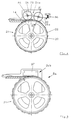
- FIG. 4 shows a further weft insertion device, which is constructed analogously to the weft insertion device 8 of FIG. 1, so that again the same parts are provided with the same reference numerals and reference is made to the explanations relating to FIG. 1.
- a second guide wheel 26a which is located on both sides of the entry point of the entry belt 14 on the drive wheel 20, is assigned to the guide member 24a for guiding the entry belt 14 on the drive wheel 20 in addition to a first guide wheel 26.
- the second guide wheel 26a is mounted on a rocker arm 82 which is mounted such that it can swing about the axis 84 of the guide wheel 26 and is biased by means of a spring 86 against the entry belt 14 or the drive wheel 20.
- FIG. 5 shows the right weft insertion device 8a of FIG. 1, but the guide member 24b is not designed as a guide wheel but as a slide guide 87.
- FIG. 6 shows the entry belt 14a already described above with the perforation 30 formed by the row of holes 32.
- the entry belt 14a can be fastened to the drive wheel 20 or to another guide device by means of the screw 18.
- the entry belt can also be connected to the drive wheel or to the guide device instead of the screw connection by means of an adhesive connection or in another suitable manner.
- an entry belt 14 can be helical in at least two rows 88a, 88b on the circumference 90 of a drive wheel 92, which at the same time serves as a guide device 93 for the tape end serves to be wound up.
- the drive wheel 92 has teeth 94 arranged in a helical path.
- the drive wheel 20 and the guide wheel 26, 26a can have teeth 22 and 28, respectively, which contain different sizes and distances and with separate rows 35, 38 interact from holes 36, 40 of corresponding size in the entry band 14b.
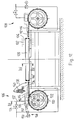
- FIG. 12 again shows a rapier weaving machine in which weft insertion devices 106, 108 are arranged on both sides of a shed 104 formed by warp threads 102.
- the shed is formed in a manner known per se by a shedding device, not shown.
- the weaving reed 109 is arranged in the shed for striking an inserted weft thread.
- the weft insertion devices 106, 108 have an identical structure.
- the weft insertion devices 106, 108 each contain a perforated flexible entry belt 114, at one end of which the hook head 110 or 112 is fastened and the other end of the belt 116 is fastened, for example by means of a screw 118, to an alternately driven drive wheel 120.
- the drive wheel 120 contains teeth 122 distributed around its circumference, which engage in holes 124 of the perforated, flexible entry belt 114, as shown in detail in FIG.
- a guide element 126 which is designed as a sliding guide, is assigned to the drive wheel 120.
- the guide member 106 shown in more detail in particular in FIG. 13, contains a slideway 128, in which compressed air outlet openings 130 are arranged, which are directed against the entry belt 114.
- a row of such compressed air outlet openings 130 is provided on both sides of the teeth 122.
- the compressed air outlet openings are connected via a feed line 132 to a compressed air source, not shown.
- a control valve 134 is arranged in the feed line 132, with which the compressed air supply to the guide member 126 can be adjusted.
- the stationary guide 136 and the guide 142 on the reed 109 in turn contain compressed air outlet openings 144 in order to reduce the friction of the rapier head and the entry belt when it is inserted into the shed.
- the compressed air outlet openings 144 are in turn connected via a feed line 146 to the compressed air source, not shown.
- a control device 148 which contains a rotating cam disk 150 which actuates a valve 152.
- FIG. 15 shows a further exemplary embodiment in which the end of the entry belt 114 is not fastened to the drive wheel 120, but the entry belt is only guided over part of the circumference of the drive wheel.
- the part 154 of the entry belt 114 facing away from the gripper head 112 leaves the drive wheel 120 and is guided in a further guide 156.
- a further guide member 158 is arranged, which is designed analogously to the guide member 126, which engages on the drive wheel 120 on the side facing the gripper head 112.
- the guide member 158 again contains compressed air outlet openings 160, which face the entry belt 114 and are connected to a compressed air source via a feed line 162.
- the two guide members 126, 158 can be designed in one piece and running over the entire wrap area of the entry belt 114 on the drive wheel 120.
- the entry belts for the rapier weaving machines can be designed in very different ways.
- they can be made of metal.
- plastic for example polyester, which are reinforced with fibers, preferably carbon fibers and / or glass fibers, are particularly advantageous.
- the entry belt is coated on both sides with fluoroplastic, ie Teflon R.
Landscapes
- Engineering & Computer Science (AREA)
- Textile Engineering (AREA)
- Looms (AREA)
Description
Die Erfindung betrifft eine Greiferwebmaschine gemäss Oberbegriff des Anspruches 1.The invention relates to a rapier weaving machine according to the preamble of
Greiferwebmaschinen der eingangs genannten Art sind mehrfach bekannt. So beschreibt beispielsweise die EP-A- 0 126 497 eine solche Greiferwebmaschine, bei der das Eintragband über einen Teil des Umfanges mit dem Treibrad in Eingriff steht, wobei sowohl am Anfang wie am Ende des Eingriffes je ein blockförmiges Führungsorgan das Eintragband am Umfang des Treibrades hält. Das dem Greiferkopf abgewandte Bandende ist in einem Führungskanal geführt. Sehr nachteilig ist es, dass die blockförmigen Führungsorgane durch die Reibung einer sehr grossen Erwärmung und grossem Verschleiss ausgesetzt sind, was sich nachteilig auf die Arbeitsgenauigkeit und die Standzeiten auswirkt. Auch die Reibung des dem Greiferkopf abgewandten Bandendes im Führungskanal führt einerseits zum Verschleiss und andererseits zu einem Kraftaufwand für das Einstossen des Eintragbandes in den Führungskanal, wodurch das Abheben des Eintragbandes vom Umfang der Treibrolle begünstigt wird. Es sind auch andere Führungsorgane bekannt, so beispielsweise aus der EP-A- 0 095 137 ein Führungsband, das längs des ganzen Bereiches des Eingriffes des Eintragbandes am Treibrad angeordnet ist und das Eintragband gegen den Umfang des Treibrades presst. Diese Vorrichtung ist relativ kompliziert und erfordert eine relativ hohe Antriebskraft aufgrund der zahlreichen Führungs- und Umlenkrollen des Führungsbandes.Rapier looms of the type mentioned are known several times. For example, EP-A-0 126 497 describes such a rapier weaving machine in which the entry belt engages with the drive wheel over part of the circumference, with a block-shaped guide member at the beginning and at the end of the engagement, the entry belt on the circumference of the drive wheel holds. The end of the belt facing away from the gripper head is guided in a guide channel. It is very disadvantageous that the block-shaped guide elements are exposed to a great deal of heating and great wear due to the friction, which has a disadvantageous effect on the working accuracy and the service life. The friction of the end of the belt facing away from the gripper head in the guide channel also leads to wear on the one hand and to the application of force for pushing the entry belt into the guide channel, thereby promoting the lifting of the entry belt from the circumference of the drive roller. Other guide elements are also known, for example from EP-A-0 095 137 a guide belt which is arranged along the entire area of engagement of the entry belt on the drive wheel and presses the entry belt against the circumference of the drive wheel. This device is relatively complicated and requires a relatively high driving force due to the numerous guide and deflection rollers of the guide belt.
Es sind auch Greiferwebmaschinen bekannt, die mit nichtperforierten Eintragbändern arbeiten. So ist beispielsweise aus der CH-A- 652 764 eine solche Greiferwebmaschine bekannt, bei der das dem Greiferkopf abgewandte Bandende fest mit einem Treibrad verbunden ist, wobei ein Eintragband verwendet wird, das nicht perforiert ist, sodass die Krafteinleitung über das Bandende erfolgt und das Band ein- oder mehrlagig auf das Treibrad aufwickelbar ist. Um das Abheben des Eintragbandes vom Treibrad zu verhindern, welche als Folge der am Bandende eingeleiteten Antriebskraft und/oder als Folge der Zentrifugalkraft auftritt, ist eine komplizierte Führungsvorrichtung vorgesehen, die ein Seil enthält, dessen beide Enden am Treibrad befestigt sind, und das mehrfach um das Treibrad geschlungen ist und zusätzlich über Rollen geführt ist, welche ausserhalb des Treibrades angeordnet sind. Diese Rollen dienen einerseits zum Spannen des Seiles und andererseits zum Umlenken des Seiles von einem Führungsbereich am Umfang des Treibrades auf die Oberseite des am Treibrad aufgewickelten Eintragbandes. Diese Führungsvorrichtung ist ausserordentlich kompliziert, und erfordert zusätzliche Antriebskräfte, um das Eintragband am Antriebsrad zu halten und aufgrund der verschlungenen Führung und Umlenkung des Seiles. Eine Steigerung der Drehzahl d.h. der Leistung der Greifer ist deshalb nicht möglich. Bei doppellagigem Aufwickeln des Eintragbandes ist es überdies erforderlich, dass dieses Distanzstreifen enthält, um den Zwischenraum für das Führungsseil zwischen den einzelnen Lagen des Eintragbandes sicherzustellen.Rapier weaving machines are also known which work with non-perforated entry belts. For example, such a rapier weaving machine is known from CH-A-652 764, in which the end of the belt facing away from the rapier head is firmly connected to a drive wheel, an entry belt being used which is not perforated, so that the force is introduced via the end of the belt and that One or more layers of tape can be wound onto the drive wheel. In order to prevent the entry belt from lifting off from the drive wheel, which occurs as a result of the drive force introduced at the end of the belt and / or as a result of the centrifugal force, a complicated guide device is provided which contains a rope, the two ends of which are fastened to the drive wheel, and this several times the drive wheel is looped and is additionally guided over rollers which are arranged outside the drive wheel. These rollers serve on the one hand for tensioning the rope and on the other hand for deflecting the rope from a guide area on the circumference of the drive wheel to the top of the entry belt wound on the drive wheel. This guiding device is extremely complicated and requires additional driving forces in order to hold the entry belt on the driving wheel and because of the convoluted guiding and deflection of the rope. It is therefore not possible to increase the speed, ie the performance of the grippers. In the case of double-layer winding of the entry belt, it is also necessary that this contain spacer strips in order to ensure the space for the guide rope between the individual layers of the entry belt.
Aus der DE-A-32 40 972 ist eine weitere Greiferwebmaschine der eingangs genannten Art bekannt, bei der das dem Greiferkopf abgewandte Bandende am Umfang eines Treibrades befestigt ist. Das Treibrad muss relativ gross gehalten werden, um eine dem Hub des Greiferkopfes entsprechende Länge des Eintragbandes aufnehmen zu können. Zur Bewältigung der bekannten Massenkräfte weist die Greiferwebmaschine federnde Einrichtungen auf, die im Bewegungsendbereich eines oszillierenden Gliedes der Antriebsvorrichtung für das Eintragband derart angeordnet sind, dass die kinetische Energie des oszillierenden Gliedes am Ende der Schwingbewegung eines Arbeitshubes des Eintragbandes an der federnden Einrichtung absorbiert und gespeichert wird, um die gespeicherte Energie bei Beginn der oszillierenden Bewegung in der Gegenrichtung, d.h. beim nächsten Arbeitshub wieder an das oszillierende Glied abzugeben. Abgesehen von der komplizierten Ausbildung stört die energiespeichernde Einrichtung die Steuerung der Webmaschine beim Wechsel der Antriebsbedingungen.From DE-A-32 40 972 a further rapier weaving machine of the type mentioned is known, in which the end of the belt facing away from the rapier head is attached to the circumference of a driving wheel. The drive wheel must be kept relatively large in order to be able to accommodate a length of the entry belt that corresponds to the stroke of the gripper head. To cope with the known inertial forces, the rapier weaving machine has resilient devices which are arranged in the movement end region of an oscillating member of the drive device for the entry belt in such a way that the kinetic energy of the oscillating member is absorbed and stored at the end of the oscillating movement of a working stroke of the entry belt on the resilient device in order to deliver the stored energy back to the oscillating link at the beginning of the oscillating movement in the opposite direction, ie at the next working stroke. Apart from the complicated design, the energy-storing device interferes with the control of the weaving machine when the drive conditions change.
Die Drehzahlen dieser bekannten Webmaschinen sind aufgrund der beschriebenen Probleme auf 400 bis 600 U/min. beschränkt.The speeds of these known weaving machines are due to the problems described 400 to 600 U / min. limited.
Aufgabe der Erfindung ist es, eine Greiferwebmaschine der eingangs genannten Art so auszubilden, dass eine Drehzahlsteigerung beispielsweise auf 1000 U/min. möglich ist und dass dabei dennoch eine einfache Führung des Eintragbandes gewährleistet ist, welche nur geringem Verschleiss unterliegt und nur geringe Antriebskräfte erfordert und die Zentrifugalkräfte in sich aufnimmt.The object of the invention is to design a rapier weaving machine of the type mentioned at the outset in such a way that an increase in speed, for example to 1000 rpm. is possible and that a simple guiding of the entry belt is still guaranteed, which is subject to only slight wear and tear and requires only low driving forces and absorbs the centrifugal forces.
Die gestellte Aufgabe wird erfindungsgemäss durch die kennzeichnenden Merkmale des Anspruches 1 gelöst. Dadurch, dass das Eintragband perforiert ausgeführt ist und durch ein verzahntes Treibrad in Umfangsrichtung angetrieben wird, so dass die Krafteinleitung praktisch in Bewegungsrichtung des Greiferkopfes abgegeben bzw. aufgenommen wird und dass das dem Greiferkopf abgewandte Bandende an einer dem Treibrad nachgeschalteten drehbaren Führungsvorrichtung grösseren Durchmessers befestigt ist, kann das Treibrad besonders klein und damit massearm ausgebildet sein. Da weiter die nachgeschaltete Führungsvorrichtung keine Antriebskräfte bewältigen muss, kann sie relativ gross und dennoch besonders leicht und damit ebenfalls massearm ausgebildet sein, ausserdem entfallen die für Führungskanäle erforderlichen Reibungskräfte, was nicht nur einer Schonung des Eintragbandes zugute kommt, sondern auch das Abheben des Eintragbandes vom Umfang des Treibrades verhindert. Dies insbesondere auch dann, wenn beispielsweise die Führungsvorrichtung antriebsmässig mit dem Treibrad gekoppelt ist, sodass das Treibrad keinerlei Zug- oder Druckkräfte für den Abschnitt des Eintragbandes aufwenden muss, welcher dem Greiferkopf abgewandt ist. Der Antrieb und die Führung des Eintragbandes kann somit ausserordentlich reibungsarm sein, weil die Antriebskraft und die Zentrifugalkraft durch das in Umfangsrichtung verzahnte Eingreifen von Eintragband und Antriebsrad und durch das befestigte Eintragbandende mit der rundlaufenden Führungsvorrichtung aufgenommen wird, wodurch kein Verschleiss entsteht, was sich auf die Genauigkeit und hohe Standzeit der Greiferwebmaschine äusserst günstig auswirkt. Die geringen Massen- und Reibungskräfte verringern die erforderlichen Antriebskräfte. Dies führt schliesslich alles dazu, dass wesentlich höhere Geschwindigkeiten bis zu 1000 U/min möglich sind und dies praktisch ohne Verschleiss, was gleichbedeutend ist mit geräuscharmem Lauf, erhöhten Standzeiten der Greiferwebmaschine und geringen Vibrationen.The object is achieved according to the invention by the characterizing features of
Vorteilhafte Ausbildungen der Greiferwebmaschine sind in den Ansprüchen 2 bis 26 beschrieben.Advantageous designs of the rapier weaving machine are described in
Die Führungsvorrichtung für das dem Greiferkopf abgewandte Bandende des Eintragbandes kann gemäss Anspruch 2 ein zusätzliches Führungsrad aufweisen. Dieses kann entweder durch das bewegte Eintragband angetrieben werden, vorzugsweise ist das Führungsrad jedoch antriebsmässig mit dem Treibrad gekoppelt. Die Massenkräfte lassen sich weiter reduzieren, wenn die Führungsvorrichtung nach Anspruch 3 ausgestaltet ist.The guide device for the belt end of the entry belt facing away from the gripper head can have an additional guide wheel according to
Insbesondere, wenn die Führungsvorrichtung unabhängig vom Treibrad angeordnet ist, empfiehlt sich ein weiteres Führungsorgan gemäss Anspruch 4.In particular, if the guide device is arranged independently of the driving wheel, a further guide member is recommended.
Falls die Führungsvorrichtung nicht vorteilhafterweise antriebsmässig mit dem Treibrad gekoppelt ist, sondern durch das Eintragband betätigt werden soll, ist eine Ausgestaltung nach Anspruch 5 erforderlich.If the guide device is not advantageously coupled to the drive wheel in terms of drive, but rather is to be actuated by the entry belt, an embodiment according to claim 5 is required.
Das Führungsorgan, welches auf der Seite des Greiferkopfes dem Treibrad zugeordnet ist, kann als Gleitführung gemäss Anspruch 6 ausgestaltet sein. Vorteilhafter ist jedoch eine Ausbildung nach Anspruch 7, wodurch die Reibung zwischen Eintragband und Führungsrad entfällt . Eine Verbesserung des Antriebes zwischen dem Führungsrad und dem Eintragband lässt sich durch antriebsmässige Kopplung des Führungsrades mit dem Treibrad erreichen, wobei das Führungsrad dann gleichzeitig auch zur Unterstützung des Antriebes dienen kann. Diese Eigenschaften werden noch verbessert durch eine Ausgestaltung des Führungsrades nach Anspruch 8. Dabei kann das Führungsrad mit der Perforation des Eintragbandes zusammenwirken, welche für den Eingriff mit dem Treibrad vorgesehen ist. Vorteilhafter ist jedoch eine Ausgestaltung nach Anspruch 9, da dann ein subtileres Zusammenwirken zwischen das Führungsrad und dem Eintragband gegeben ist. Die Führungseigenschaften des Führungsorganes lassen sich verbessern durch eine Ausgestaltung nach Anspruch 10 und/oder 11.The guide member, which is assigned to the drive wheel on the side of the gripper head, can be designed as a sliding guide according to
Die Greiferwebmaschine kann gemäss Anspruch 17 mit einer einzigen Schussfadeneintragvorrichtung ausgestattet sein, die von einer Seite des Webfaches durch das ganze Webfach wirksam ist. Vorteilhafter ist jedoch eine ansich bekannte Ausgestaltung nach Anspruch 12. Dabei können die Greiferköpfe gemäss Anspruch 13 gleichlange Wegstrecken zurücklegen oder gemäss Anspruch 14 auch verschiedenlage Wege. Weiter ist es möglich, dass die Greiferköpfe synchron von beiden Seiten in das Webfach eingeschoben werden oder phasenverschoben. Dabei ist es sogar möglich, dass sich der Greiferkopf, der den Schussfaden in das Webfach einzieht bereits wieder in der Rückzugsbewegung befindet, wenn der andere Greiferkopf den Schussfaden übernimmt. Gemäss Anspruch 15 ist es auch möglich, von jeder Seite des Webfaches einen Schussfaden einzubringen, die vorzugsweise gemäss Anspruch 16 miteinander verbunden werden.The rapier weaving machine can be equipped with a single weft insertion device which is effective from one side of the shed through the entire shed. However, a known embodiment according to
Besonders vorteilhaft ist eine Weiterbildung nach Anspruch 18, wobei allerdings für die Merkmale des Anspruches 18 Schutz auch unabhängig von den Merkmalen der vorausgehenden Ansprüche 1 bis 17 beansprucht wird, denn die reibungsmindernde und kühlende Wirkung der Druckluftzufuhr zur Gleitführung ist auch für andere Greiferwebmaschinen von Vorteil.A further development according to
Die Druckluft kann dabei gleichzeitig das Eintragband gegen ein Treibrad drücken, wodurch der Zentrifugalkraft des angetriebenen Eintragbandes entgegengewirkt wird und somit ein sicherer Halt des Eintragbandes am Treibrad gewährleistet ist.The compressed air can simultaneously press the entry belt against a drive wheel, which counteracts the centrifugal force of the driven entry belt and thus ensures a secure hold of the entry belt on the drive wheel.
Vorteilhafte Ausgestaltungen sind in den Ansprüchen 19 bis 24 beschrieben.Advantageous embodiments are described in claims 19 to 24.
Die Gleitführung kann auf den dem Greiferkopf zugewandten Bereich beschränkt sein, an dem das Eintragband das Treibrad verlässt. Vorteilhaft ist auch eine Ausgestaltung nach Anspruch 19, wodurch ein sicherer Halt des Eintragbandes am Treibrad gewährleistet ist. Da durch die Druckluft ein die Reibung verminderndes Luftpolster gebildet wird, kann eine solches Führungsorgan gemäss Anspruch 20 vorteilhafterweise längs des ganzen Bereiches angeordnet sein, an dem das Eintragband am Treibrad aufliegt. Dadurch wird ein sicherer Halt des Eintragbandes am Treibrad gewährleistet, wobei die Druckluft vorzugsweise so eingestellt werden kann, dass das Eintragband trotz der Zentrifugalkraft am Treibrad anliegt.The sliding guide can be limited to the area facing the gripper head, at which the entry belt leaves the driving wheel. An embodiment according to claim 19 is also advantageous, as a result of which a secure hold of the entry belt on the drive wheel is ensured. Since a friction-reducing air cushion is formed by the compressed air, such a guide element can advantageously be arranged along the entire area on which the entry belt rests on the drive wheel. This ensures a secure hold of the entry belt on the drive wheel, the compressed air preferably being able to be set such that the entry belt is in contact with the drive wheel despite the centrifugal force.
Eine Ausgestaltung nach Anspruch 21 ist besonders vorteilhaft und sorgt für eine sichere Auflage des Eintragbandes am Treibrad.An embodiment according to
Besonders vorteilhaft ist auch eine Ausgestaltung nach Anspruch 22, wodurch die Führung des Greiferkopfes und des Eintragbandes am Webblatt verbessert wird. Damit der eingetragene Schussfaden nicht durch die Druckluft verblasen wird, ist eine Ausgestaltung nach Anspruch 23 von Vorteil.An embodiment according to
Besonders zweckmässig ist auch eine Ausgestaltung nach Anspruch 24, da dann die Druckluftzufuhr an den einzelnen Verbraucherstellen den individuellen Bedürfnissen entsprechend eingestellt werden kann.An embodiment according to
Ein besonders vorteilhaftes Eintragband für Greiferwebmaschinen ist in Anspruch 25 beschrieben, dabei erzielt man mit einer Weiterbildung nach Anspruch 26 weiter verbesserte Ergebnisse.A particularly advantageous entry belt for rapier weaving machines is described in claim 25, and further improvements are achieved with a further development according to
Ausführungsbeispiele der Greiferwebmaschine werden nachfolgend anhand schematischer Zeichnungen näher beschrieben, dabei zeigen:
Figur 1- eine erste Greiferwebmaschine in Ansicht Senkrecht zur Warenrichtung gegen die Schussfadeneintragvorrichtungen, in schematischer Darstellung;
Figur 2- eine Schussfadeneintragvorrichtung zweiter Art, in schematischer Darstellung;
- Figur 3
- eine Schussfadeneintragvorrichtung dritter Art, in schematischer Darstellung;
- Figur 4
- eine Schussfadeneintragvorrichtung vierter Art, in schematischer Darstellung;
- Figur 5
- eine Schussfadeneintragvorrichtung fünfter Art, in schematischer Darstellung;
Figur 6- ein erstes Eintragband, im Ausschnitt und in Draufsicht;
- Figur 7
- die Befestigung des Bandendes des Eintragbandes im Ausschnitt;
Figur 8- ein Treibrad mit anliegendem Eintragband, im Teilschnitt VIII-
VIII der Figur 1 und im Ausschnitt; Figur 9- eine weitere Variante des Treibrades mit wendelförmig aufgewickeltem Eintragband, im Vertikalschnitt und im Ausschnitt;
Figur 10- ein weiteres Eintragband mit zwei Perforationsreihen, im Ausschnitt und Draufsicht,
- Figur 11
- das Zusammenwirken von Treibrad,
Eintragband gemäss Figur 10 und Führungsrad, im Teilschnitt XI-XI der Figur 4 und im Ausschnitt; Figur 12- eine zweite Greiferwebmaschine mit zwei Schussfadeneintragvorrichtungen, in Ansicht quer zum Warenverlauf;
- Figur 13
- das Führungsorgan an einem Treibrad gemäss Schnitt XIII-
XIII der Figur 12; Figur 14- das Webeblatt im Schnitt XIV-
XIV der Figur 12; und - Figur 15
- eine weitere Ausgestaltung von Führungsorganen an einem Treibrad.
- Figure 1
- a first rapier weaving machine in a view perpendicular to the direction of the goods against the weft insertion devices, in a schematic representation;
- Figure 2
- a weft insertion device of the second kind, in a schematic representation;
- Figure 3
- a weft insertion device of the third type, in a schematic representation;
- Figure 4
- a weft insertion device of the fourth type, in a schematic representation;
- Figure 5
- a weft insertion device of the fifth type, in a schematic representation;
- Figure 6
- a first entry tape, in the detail and in plan view;
- Figure 7
- the fastening of the tape end of the entry tape in the cutout;
- Figure 8
- a driving wheel with adjacent entry belt, in partial section VIII-VIII of Figure 1 and in section;
- Figure 9
- a further variant of the driving wheel with a helically wound entry belt, in vertical section and in the cutout;
- Figure 10
- another ribbon with two rows of perforations, in the cutout and top view,
- Figure 11
- the interaction of the driving wheel, the entry belt according to FIG. 10 and the guide wheel, in the partial section XI-XI of FIG. 4 and in the section;
- Figure 12
- a second rapier weaving machine with two weft insertion devices, in view transverse to the course of the goods;
- Figure 13
- the guide member on a drive wheel according to section XIII-XIII of Figure 12;
- Figure 14
- the reed in section XIV-XIV of Figure 12; and
- Figure 15
- a further embodiment of management bodies on a driving wheel.
Die Figur 1 zeigt einer Greiferwebmaschine, bei der beidseits eines durch Kettfäden 2 gebildeten Webfaches 4 Schussfadeneintragvorrichtungen 6, 8 angeordnet sind. Das Webfach wird in an sich bekannter Weise durch nicht dargestellte Fachbildemaschinen wie z.B. durch eine elektronisch gesteuerte Jacquardmaschine über Harnischschnüre 9 und Litzen gebildet. Diese Schussfadeneintragvorrichtungen 6, 8 weisen mit Ausnahme modifizierter Greiferköpfe 10, 12 einen identischen Aufbau auf. Die Schussfadeneintragvorrichtungen 6, 8 enthalten jeweils ein perforiertes biegsames Eintragband 14, an dessen einem Bandende der Greiferkopf 10 bzw. 12 befestigt ist und dessen anderes Bandende 16 beispielsweise mittels einer Schraube 18 an einem alternierend angetriebenen Treibrad 20 befestigt ist. Das Treibrad 20 dient damit gleichzeitig als Führungsvorrichtung 21 für das Bandende 16 und bewegt dieses während des ganzen Arbeitshubes auf einer kreisförmigen Führungsbahn.FIG. 1 shows a rapier weaving machine in which 4
Das Treibrad 20 enthält an seinem Umfang verteilt angeordnete Zähne 22, die in Löcher des perforierten biegsamen Eintragbandes 14 eingreifen, wie in Figur 8 im Detail dargestellt ist. Ein solches Eintragband kann beispielsweise gemäss den Figuren 6 und 10 ausgebildet sein, wie nachfolgend noch näher beschrieben wird. Dem Treibrad 20 ist ein Führungsorgan 24 zugeordnet, das als Gleitführung oder wie dargestellt als Führungsrad 26 ausgebildet ist, welches an seinem Umfang ebenfalls mit Zähnen 28 versehen ist. Das Führungsrad 26 greift an jenem Bereich des Eintragbandes 14 an, welches dem Greiferkopf 10 bzw. 12 zugeordnet ist und sorgt dafür, dass das Eintragband 14 in engem Eingriff mit dem Treibrad 20 steht und während des Antriebes nicht abhebt.The
Die Zähne 28 des Führungsrades 26 können die gleiche Grösse aufweisen wie die Zähne 22 des Treibrades 20 und in die gleichen Löcher eingreifen, in die auch die Zähne 22 des Treibrades 20 eingreifen, sodass beispielsweise ein Eintragband 14a gemäss Figur 6 verwendet werden kann, welches eine Perforation 30 mit Löchern 32 gleicher Grösse aufweist. Im vorliegenden Beispiel hat das Führungsrad 26 jedoch Zähne 28, die kleiner sind als die Zähne 22 des Treibrades 20 und es ist hierfür ein Eintragband 14b erforderlich, wie dies in Figur 10 gezeigt ist. Ein solches Eintragband hat eine Perforation 34 mit einer ersten Reihe 35 mit Löchern 36, die für die Zähne 22 des Treibrades 20 bestimmt sind, und eine zweite Reihe 38 mit Löchern 40, deren Grösse und Abstände kleiner sein kann als jene der Löcher 36 der ersten Reihe 34, und die zum Eingriff der Zähne 28 des Führungsrades 26 bestimmt sind.The
Bei der Greiferwebmaschine der Figur 1 weist die linke Schussfadeneintragvorrichtung 6 einen Greiferkopf 10 auf, der gabelförmig ausgestaltet ist und zum Erfassen eines Schussfadens 42 dient, der beispielsweise von einer Vorratsspule 44 abgezogen wird. Der Greiferkopf 12 der rechten Schussfadeneintragvorrichtung 8 ist hakenförmig ausgestaltet und dient zur Uebernahme des vom Greiferkopf 10 vorgelegten Schussfadens. Die Schussfadeneintragvorrichtungen sind so ausgestaltet, dass die Greiferköpfe 10, 12 synchron gegeneinander bewegt werden und jeweils die Hälfte der Länge des Webfaches 4 durchqueren bis zur Uebergabestelle 46, an der der Greiferkopf 12 den Schussfaden 42 vom Greiferkopf 10 erfasst und weiter durch das Webfach bis auf die andere Seite desselben zieht. Im vorliegenden Beispiel sind also beide Schussfadeneintragvorrichtungen 6, 8 identisch ausgestaltet und ihre Greiferköpfe 10, 12 bestreichen jeweils in ihrem Arbeitshub die Hälfte der Breite des Webfaches 4. Es ist aber durchaus auch möglich, dass die beiden Schussfadeneintragvorrichtungen unterschiedliche Arbeitshübe aufweisen, sodass der Uebergabebereich nach links oder rechts im Webfach verschoben sein kann. Ferner ist es möglich, dass die Bewegungsabläufe nicht synchron gegeneinander erfolgen, sondern phasenverschoben, wobei beispielsweise einer der Greiferköpfe vor dem anderen den Uebergabebereich 46 erreicht. Es ist sogar möglich, die Schussfadeneintragvorrichtungen so auszugestalten, dass beispielsweise der Greiferkopf 10 bereits die Rückzugsbewegung ausführt und in dieser vom Greiferkopf 12 eingeholt wird. Ferner ist es möglich, dass die Schussfadeneintragvorrichtungen unterschiedlich ausgebildet sind und nach einem anderen Prinzip arbeiten, sodass beispielsweise die rechte Schussfadeneintragvorrichtung 8 der Figur 1 auch gemäss CH-A- 671 412 ausgestaltet sein kann.In the rapier weaving machine of FIG. 1, the left weft
Die Figur 2 zeigt eine weitere Schussfadeneintragvorrichtung 48, bei der einem verzahnten Treibrad 50 mit dem Radius r eine Führungsvorrichtung 52 in Form eines Führungsrades 54 mit dem Radius R, wobei R>r ist, zugeordnet ist, an dem das Bandende 56 eines Eintragbandes 58 befestigt ist und in einer kreisförmigen Führungsbahn aufgewickelt wird. An der Seite des Greiferkopfes 60 wird das Eintragband 58 wiederum von einem verzahnten oder unverzahnten als Führungsorgan 61 dienenden Führungsrad 62 zum Treibrad 50 geführt. Zwischen dem Treibrad 50 und dem Führungsrad 54 steht ein weiteres Führungsrad 64 am Eintragband 58 am Aus- bzw. Einlaufbereich am Treibrad 50 an. Die Führungsräder 54, 62, 64 können freilaufend sein und lediglich durch das vom Treibrad 50 getriebene Eintragband 58 bewegt werden. Es ist aber auch möglich, dass das Treibrad 50 das Führungsrad 54 antreibt, wie dies durch das strichpunktiert dargestellte Zahnriemengetriebe 66 angedeutet ist. Durch ein entsprechendes Zahnriemengetriebe 68 können auch die Führungsräder 62, 64 angetrieben sein.FIG. 2 shows a further
Die Figur 3 zeigt ein weiteres Ausführungsbeispiel einer Schussfadeneintragvorrichtung, welche ähnlich aufgebaut ist, wie jene der Figur 2, sodass gleiche Teile mit gleichen Bezugszeichen versehen sind. Anstelle des Führungsrades 54 in Figur 2 ist jedoch bei dem Ausführungsbeispiel der Figur 3 der Treibrolle 50 ein Führungsarm 70 mit der Länge bzw. dem Radius R zugeordnet, der an einem Ende an einer Welle 72 befestigt ist und an seinem anderen Ende 74 das Bandende 56 des Eintragbandes 58 längs einer kreisförmigen Führungsbahn mit dem Radius R trägt. Dem Treibrad 50 ist eine Führungsrolle 76 nachgeschaltet, die an einem Tragarm 78 befestigt ist. Der Führungsarm 70 könnte auch mittels eines strichpunktiert angedeuteten Rädergetriebes 80 synchron mit dem Treibrad 50 angetrieben werden. Entsprechend kann auch das Führungsrad 62 mittels des strichpunktiert angedeuteten Zahnriemengetriebes 68 synchron betätigt werden.FIG. 3 shows a further exemplary embodiment of a weft insertion device which is constructed similarly to that of FIG. 2, so that the same parts are provided with the same reference symbols. Instead of the
Die Figur 4 zeigt eine weitere Schussfadeneintragvorrichtung, die analog der Schussfadeneintragvorrichtung 8 der Figur 1 aufgebaut ist, sodass wiederum gleiche Teile mit gleichen Bezugszeichen versehen sind und auf die Ausführungen zu Figur 1 Bezug genommen wird. Im Falle der Ausführung gemäss Figur 4 ist dem Führungsorgan 24a zur Führung des Eintragbandes 14 am Treibrad 20 neben einem ersten Führungsrad 26 ein zweites Führungsrad 26a zugeordnet, die beidseits der Einlaufstelle des Eintragbandes 14 am Treibrad 20 liegen. Das zweite Führungsrad 26a ist an einer Schwinge 82 gelagert, die um die Achse 84 des Führungsrades 26 schwingbar gelagert ist und mittels einer Feder 86 gegen das Eintragband 14 bzw. das Treibrad 20 vorgespannt ist.FIG. 4 shows a further weft insertion device, which is constructed analogously to the
Die Figur 5 zeigt die rechte Schussfadeneintragvorrichtung 8a der Figur 1, wobei jedoch das Führungsorgan 24b nicht als Führungsrad sondern als Gleitführung 87 ausgebildet ist.FIG. 5 shows the right
Die Figur 6 zeigt das bereits oben beschriebene Eintragband 14a mit der durch die Reihe der Löcher 32 gebildeten Perforation 30. Das Eintragband 14a kann, wie ebenfalls erwähnt und in Figur 7 gezeigt mittels der Schraube 18 am Treibrad 20 oder an einer anderen Führungsvorrichtung befestigt sein. Das Eintragband kann aber auch anstelle der Schraubverbindung mittels Klebeverbindung oder auf andere geeignete Weise mit dem Treibrad bzw. mit der Führungsvorrichtung verbunden sein.FIG. 6 shows the
Wie Figur 9 zeigt, kann ein Eintragband 14 in mindestens zwei Reihen 88a, 88b wendelförmig am Umfang 90 eines Treibrades 92, welches gleichzeitig als Führungsvorrichtung 93 für das Bandende dient, aufgewickelt werden. Hierzu weist das Treibrad 92 in einer wendelförmigen Bahn angeordnete Zähne 94 auf. Um das Eintragband bezüglich des Webfaches stets in ausgerichteter Stellung ablaufen zu lassen, kann es zweckmässig sein, das Treibrad entsprechend der Steigung der wendelförmigen Bahn der Zähne 94 in nicht näher dargestellter Weise in axialer Richtung hin- und herfahrbar anzuordnen.As FIG. 9 shows, an
Wie bereits im Zusammenhang mit dem Ausführungsbeispiel der Figuren 1 und 4 erwähnt und aus den Figuren 10 und 11 näher hervorgeht, können das Treibrad 20 und das Führungsrad 26, 26a Zähne 22 bzw. 28 aufweisen, die unterschiedliche Grössen und Abstände enthalten und mit getrennten Reihen 35, 38 aus Löchern 36, 40 entsprechender Grösse im Eintragband 14b zusammenwirken.As already mentioned in connection with the exemplary embodiment in FIGS. 1 and 4 and can be seen in greater detail in FIGS. 10 and 11, the
Die Figur 12 zeigt wiederum einer Greiferwebmaschien, bei der beidseits eines durch Kettfäden 102 gebildeten Webfaches 104 Schussfadeneintragvorrichtungen 106, 108 angeordnet sind. Das Webfach wird in an sich bekannter Weise durch eine nicht näher dargestellte Fachbildevorrichtung gebildet. Im Webfach ist das Webeblatt 109 zum Anschlagen eines eingetragenen Schussfadens angeordnet. Die Schussfadeneintragvorrichtung 106, 108 weisen mit Ausnahme modifizierte Greiferköpf 110, 112 einen identischen Aufbau auf.FIG. 12 again shows a rapier weaving machine in which
Die Schussfadeneintragvorrichtungen 106, 108 enthalten jeweils ein perforiertes biegsames Eintragband 114, an dessen einem Ende der Greiferkopf 110 bzw. 112 befestigt ist und dessen anderes Bandende 116 beispielsweise mittels einer Schraube 118 an einem alternierend angetriebenen Treibrad 120 befestigt ist. Das Treibrad 120 enthält an seinem Umfang verteilt angeordnet Zähne 122, die in Löcher 124 des perforierten biegsamen Eintragbandes 114 eingreifen, wie dies in Figur 13 im Detail dargestellt ist. Dem Treibrad 120 ist ein Führungsorgan 126 zugeordnet, das als Gleitführung ausgebildet ist.The
Das insbesondere in Figur 13 näher dargestellte Führungsorgan 106 enthält eine Gleitbahn 128, in der Druckluft-Austrittsöffnungen 130 angeordnet sind, die gegen das Eintragband 114 gerichtet sind. Beidseits der Zähne 122 ist jeweils eine Reihe solches Druckluft-Austrittsöffnungen 130 vorhanden. Die Druckluft-Austrittsöffnungen sind über eine Zuleitung 132 mit einer nicht näher dargestellten Druckluftquelle verbunden. In der Zuleitung 132 ist ein Regelventil 134 angeordnet, mit dem die Druckluftzufuhr zum Führungsorgan 126 eingestellt werden kann.The
Der Greiferkopf 110 liegt auf einer Führung 136 auf, um einen Faden 138 von einer Vorratsspule 140 zu erfassen und in das Webfach 104 einzubringen. Der Greiferkopf 110 fördert den Faden 138 etwa bis zur Mitte des Webfaches, wo er von dem Greiferkopf 112 der zweiten Schussfadeneintragvorrichtung 108 übernommen und aus dem Webfach auf die andere Seite ausgezogen wird. Längs des Weges durch das Webfach sind die Greiferköpfe 110, 112 auf einer Führung 142 geführt, die am Webeblatt 109 angeordnet ist, wie sich insbesondere aus Figur 14 ergibt.The rapier head 110 rests on a
Die stationäre Führung 136 und die Führung 142 am Webblatt 109 enthalten wiederum Druckluft-Austrittsöffnungen 144, um die Reibung des Greiferkopfes und des Eintragbandes beim Einführen in das Webfach zu vermindern. Die Druckluft-Austrittsöffnungen 144 sind wiederum über eine Zuleitung 146 mit der nicht näher dargestellten Druckluftquelle verbunden. In der Zuleitung 146 ist eine Steuervorrichtung 148 vorhanden, welche eine rotierende Nockenscheibe 150 enthält, welche ein Ventil 152 betätigt. Mittels der Steuervorrichtung 148 kann die Druckluftzufuhr in der Phase des Webvorganges abgestellt werden, in welcher das Webeblatt 109 den eingetragenen Schussfaden an der Ware zum Anschlag bringt.The
Die Figur 15 zeigt ein weiteres Ausführungsbeispiel, bei dem das Ende des Eintragbandes 114 nicht am Treibrad 120 befestigt ist, sondern das Eintragband nur über einen Teil des Umfanges des Treibrades geführt ist. Der dem Greiferkopf 112 abgewandte Teil 154 des Eintragbandes 114 verlässt das Treibrad 120 und ist in einer weiteren Führung 156 geführt. An dieser Abgangsstelle des Teiles 154 ist ein weiteres Führungsorgan 158 angeordnet, welches analog dem Führungsorgan 126 ausgebildet ist, welches an der dem Greiferkopf 112 zugewandten Seite am Treibrad 120 angreift. Auch das Führungsorgan 158 enthält wieder Druckluft-Austrittsöffnungen 160, welche dem Eintragband 114 zugewandt sind und über eine Zuleitung 162 an eine Druckluftquelle angeschlossen sind. Anstelle der dargestellten Ausführungsform können die beiden Führungsorgane 126, 158 einstückig und über den ganzen Umschlingungsbereich des Eintragbandes 114 am Treibrad 120 verlaufend ausgestaltet sein.FIG. 15 shows a further exemplary embodiment in which the end of the
Die Eintragbänder für die Greiferwebmaschinen können sehr verschieden ausgebildet sein. So können sie beispielsweise aus Metall bestehen. Besonders vorteilhaft sind solche aus Kunststoff, beispielsweise Polyester, die mit Fasern, vorzugsweise Kohlenstofffasern und/oder Glasfasern verstärkt sind. Zur Verminderung der Reibung ist das Eintragband beidseits mit Fluorkunststoff, d.h. TeflonR beschichtet.The entry belts for the rapier weaving machines can be designed in very different ways. For example, they can be made of metal. Those made of plastic, for example polyester, which are reinforced with fibers, preferably carbon fibers and / or glass fibers, are particularly advantageous. To reduce friction, the entry belt is coated on both sides with fluoroplastic, ie Teflon R.
- RR
- Radiusradius
- rr
- Radiusradius
- 22nd
- KettfadenWarp thread
- 44th
- WebfachShed
- 66
- SchussfadeneintragvorrichtungWeft insertion device
- 88th
- SchussfadeneintragvorrichtungWeft insertion device
- 8a8a
- SchussfadeneintragvorrichtungWeft insertion device
- 99
- HarnischschnurHarness cord
- 1010th
- GreiferkopfGripper head
- 1212th
- GreiferkopfGripper head
- 1414
- EintragsbandEntry volume
- 14a14a
- Eintragsband (Fig. 6)Entry tape (Fig. 6)
- 14b14b
- Eintragsband (Fig. 10)Entry tape (Fig. 10)
- 1616
- BandendeBand end
- 1818th
- Schraubescrew
- 2020th
- TreibradDriving wheel
- 2121
- Führungsvorrichtung von 16Guide device of 16
- 2222
- Zahntooth
- 2424th
- FührungsorganExecutive body
- 24a24a
- FührungsorganExecutive body
- 24b24b
- FührungsorganExecutive body
- 2626
- FührungsradGuide wheel
- 26a26a
- FührungsradGuide wheel
- 2828
- Zahn von 26Tooth of 26
- 3030th
- Perforation von 14aPerforation of 14a
- 3232
- Loch von 14aHole from 14a
- 3434
- Perforation von 14bPerforation of 14b
- 3535
- erste Reihe von 14bfirst row of 14b
- 3636
- Lochhole
- 3838
- zweite Reihe von 14bsecond row of 14b
- 4040
- Lochhole
- 4242
- SchussfadenWeft
- 4444
- VorratsspuleSupply spool
- 4646
- UebergabebereichTransfer area
- 4848
- SchussfadeneintragvorrichtungWeft insertion device
- 5050
- TreibradDriving wheel
- 5252
- FührungsvorrichtungGuide device
- 5454
- FührungsradGuide wheel
- 5656
- BandendeBand end
- 5858
- EintragsbandEntry volume
- 6060
- GreiferkopfGripper head
- 6161
- FührungsorganExecutive body
- 6262
- FührungsradGuide wheel
- 6464
- FührungsradGuide wheel
- 6666
- Zahnriemengetriebe für 54Timing belt gear for 54
- 6868
- Zahnriemengetriebe für 62Timing belt gear for 62
- 7070
- FührungsarmGuide arm
- 7272
- Wellewave
- 7474
- Ende von 70Late 70s
- 7676
- FührungsrolleLeadership role
- 7878
- TragarmBeam
- 8080
- RädergetriebeGear transmission
- 8282
- SchwingeSwingarm
- 8484
- Achseaxis
- 8686
- Federfeather
- 8787
- GleitführungSliding guide
- 88a88a
- Reiheline
- 88b88b
- Reiheline
- 9090
- Umfangscope
- 9292
- TreibradDriving wheel
- 9393
- FührungsvorrichtungGuide device
- 9494
- Zahntooth
- 102102
- KettfadenWarp thread
- 104104
- WebfachShed
- 106106
- SchussfadeneintragvorrichtungWeft insertion device
- 108108
- SchussfadeneintragvorrichtungWeft insertion device
- 109109
- WebeblattReed
- 110110
- GreiferkopfGripper head
- 112112
- GreiferkopfGripper head
- 114114
- EintragbandEntry tape
- 116116
- BandendeBand end
- 118118
- Schraubescrew
- 120120
- TreibradDriving wheel
- 122122
- Zahntooth
- 124124
- Lochhole
- 126126
- FührungsorganExecutive body
- 128128
- GleitbahnSlideway
- 130130
- Druckluft-AustrittsöffnungCompressed air outlet opening
- 132132
- ZuleitungSupply
- 134134
- RegelventilControl valve
- 136136
- Führungguide
- 138138
- Fadenthread
- 140140
- VorratsspuleSupply spool
- 142142
- Führung an 9Guided tour on 9
- 144144
- Druckluft-AustrittsöffnungCompressed air outlet opening
- 146146
- ZuleitungSupply
- 148148
- SteuervorrichtungControl device
- 150150
- NockenscheibeCam disc
- 152152
- VentilValve
- 154154
- Teil von 14Part of 14
- 156156
- Führungguide
- 158158
- FührungsorganExecutive body
- 160160
- Druckluft-AustrittsöffnungCompressed air outlet opening
- 162162
- ZuleitungSupply
Claims (26)
- Gripper weaving machine, with at least one weft-insertion device having a perforated flexible insertion band (14, 14a, 14b, 58, 114) which carries a gripper head (10, 12, 60, 110, 112) at one band end and which is advanced into the shed (4, 104) and retracted again by means of a driving wheel (50) driven in alternation, the driving wheel having teeth (22, 94, 122) distributed on the circumference and engaging into the perforation (30, 34, 124) of the insertion band, there being, furthermore, a guide member (24, 24a, 24b, 61, 87, 126), assigned to the driving wheel on the same side as the gripper head, for preventing the insertion band from lifting off from the circumference of the driving wheel, characterized in that the band end (56) facing away from the gripper head (60) is fastened to a rotatable guide device (52) located downstream of the driving wheel (50), the entire assembly being such that, during the entire working stroke, the band end (56) describes an at least approximately circular guide path, the radius (R) of which is larger than the radius (r) of the driving wheel (50).
- Gripper weaving machine according to Claim 1, characterized in that the guide device (52) has a guide wheel (54) which is located downstream of the driving wheel (50) and which is preferably drive-coupled to the driving wheel (50).
- Gripper weaving machine according to Claim 1, characterized in that the guide device (52) has a guide arm (70) which is located downstream of the driving wheel (50) and to one end (70) of which the band end (56) is fastened and the other end of which is mounted rotatably about a shaft (72) arranged parallel to the axis of the driving wheel (50), the guide arm (70) being preferably drive-coupled to the driving wheel (50).
- Gripper weaving machine according to one of Claims 1 to 3, characterized in that, in the guide device (52) assigned to the driving wheel (50), a further guide member (64) for the insertion band (58), the said guide member (64) preferably being assigned to the driving wheel (50), is present between the guide device (52) and the driving wheel (50).
- Gripper weaving machine according to one of Claims 1 to 4, characterized in that the insertion band (58) is made bend-resistant, in such a way that it drives the guide device (52) located downstream of the driving wheel (50).
- Gripper weaving machine according to one of Claims 1 to 5, characterized in that the guide member (24b, 126) assigned to the driving wheel (20, 120) on the same side as the gripper head (10, 12, 110, 112) is designed as a sliding guide (87, 128) and preferably consists of a slidable and wearable material.
- Gripper weaving machine according to one of Claims 1 to 6, characterized in that the guide member (24, 24a, 61) assigned to the driving wheel (20, 50) on the same side as the gripper head (10, 12, 60) is designed as a guide wheel (26, 26a, 62) which is preferably drive-coupled to the driving wheel (20, 50).
- Gripper weaving machine according to Claim 7, characterized in that the guide wheel (26, 26a, 62) is equipped along the circumference with teeth (28) which cooperate with the insertion band (14, 14a, 14b).
- Gripper weaving machine according to Claim 8, characterized in that the perforation (34) of the insertion band (14b) has at least one second row (38) of holes (40) for the engagement of the teeth (28) of the guide wheel (26), the spacing and size of the holes (40) of the second row (38) preferably being smaller than the spacing and size of the holes (36) of the first row (35).
- Gripper weaving machine according to one of Claims 1 to 9, characterized in that the guide member (24a) bears on the insertion band (14) under pretension by means of a spring (86).
- Gripper weaving machine according to one of Claims 1 to 10, characterized in that it has two guide members (26, 26a, 126, 158) which are arranged on both sides of the run-on region of the insertion band (14, 114) on the driving wheel (20, 120).
- Gripper weaving machine according to one of Claims 1 to 11, characterized in that it has, on each side of the shed (4), a weft-insertion device (6, 8), the gripper heads (10, 12) of which, acting in opposition to one another, each travel through part of the width of the shed, in such a way that the weft thread (42) drawn into the shed (4) by one gripper head (10) is taken over by the other gripper head (12) and drawn through the shed (4) completely.
- Gripper weaving machine according to Claim 12, characterized in that the gripper heads (10, 12, 110, 112) have approximately identical working strokes.
- Gripper weaving machine according to Claim 12, characterized in that the gripper heads (10, 12, 110, 112) have working strokes of different length.
- Gripper weaving machine according to one of Claims 1 to 11, characterized in that it has, on each side of the shed (4), a weft-insertion device (6), the gripper heads (10) of which act in opposition to one another and travel through a corresponding part of the shed, in such a way that the left-hand and right-hand grippers each insert one weft thread, so that two fabric portions are obtained.
- Gripper weaving machine according to Claim 15, characterized in that the weft-thread tips are connected to one another in such a way that a fabric is obtained.
- Gripper weaving machine according to one of Claims 1 to 11, characterized in that the gripper head of the weft-insertion device travels through the entire width of the shed and draws the weft thread in completely over the entire fabric width.
- Gripper weaving machine according to one of Claims 1 to 17, with at least one weft-insertion device (106, 108) having a flexible insertion band (114) which carries a gripper head (110, 112) at one band end, and with at least one guide member (126) for the insertion band (114), characterized in that the guide member (126) is designed as a sliding guide, in the slide track (128) of which are arranged outflow orifices (130) for compressed air which point towards the insertion band (114) and which are connected to a compressed-air source.
- Gripper weaving machine according to Claim 18, characterized in that a further guide member (158) having a slide track and compressed-air outflow orifices (160) pointing towards the insertion band (114) are assigned to the driving wheel (120) at a location where the part (154) of the insertion band (114) facing away from the gripper head (112) runs onto the driving wheel (120) or leaves the latter.
- Gripper weaving machine according to Claim 18, characterized in that the guide member (126, 158) together with the slide track (128) and the compressed-air outflow orifices (130, 160) is arranged along the entire region on which the insertion band (114) rests against the driving wheel (120).
- Gripper weaving machine according to one of Claims 18 to 20, characterized in that the compressed-air outflow orifices (130, 160) are arranged on both sides of the perforation row.
- Gripper weaving machine according to one of Claims 18 to 21, characterized in that the gripper head (110, 112) and the insertion band (114) are guided, in the region of the shed (104), on a guide (142) which is arranged on the reed (109) and which has compressed-air outflow orifices (144) pointing towards the insertion band (114) and the gripper head (110, 112).
- Gripper weaving machine according to one of Claims 18 to 21, characterized in that there is arranged in the compressed-air feed conduit (146) assigned to the reed (109) a control device (148) which interrupts the compressed-air feed at least in the phase of the beating-up of the weft thread.
- Gripper weaving machine according to one of Claims 18 to 21, characterized in that means (134) for adjusting the compressed-air feed are present at least in individual compressed-air feed conduits (132).
- Gripper weaving machine according to one of Claims 1 to 24, characterized in that the insertion band (14, 114) is a fibre-reinforced plastic band which is coated on both sides with fluoroplastic (Teflon®).
- Gripper weaving machine according to Claim 25, characterized in that the insertion band (14, 114) consists of polyester and contains carbon fibres and/or glass fibres.
Applications Claiming Priority (4)
| Application Number | Priority Date | Filing Date | Title |
|---|---|---|---|
| CH129687 | 1987-04-03 | ||
| CH1296/87 | 1987-04-03 | ||
| CH3847/87 | 1987-10-02 | ||
| CH384787 | 1987-10-02 |
Publications (3)
| Publication Number | Publication Date |
|---|---|
| EP0285001A2 EP0285001A2 (en) | 1988-10-05 |
| EP0285001A3 EP0285001A3 (en) | 1992-04-29 |
| EP0285001B1 true EP0285001B1 (en) | 1994-08-03 |
Family
ID=25687234
Family Applications (1)
| Application Number | Title | Priority Date | Filing Date |
|---|---|---|---|
| EP88104717A Expired - Lifetime EP0285001B1 (en) | 1987-04-03 | 1988-03-24 | Gripper loom |
Country Status (6)
| Country | Link |
|---|---|
| US (1) | US5097873A (en) |
| EP (1) | EP0285001B1 (en) |
| JP (1) | JPH01502762A (en) |
| DE (1) | DE3850899D1 (en) |
| ES (1) | ES2058162T3 (en) |
| WO (1) | WO1988007600A1 (en) |
Families Citing this family (16)
| Publication number | Priority date | Publication date | Assignee | Title |
|---|---|---|---|---|
| IT1218006B (en) * | 1988-05-27 | 1990-03-30 | Nuovo Pignone Spa | PERFECTED DRIVE SYSTEM FOR FLEXIBLE TAPES CLAMP HOLDERS IN TEXTILE FRAMES WITHOUT SHUTTLE |
| IT1236649B (en) * | 1989-11-03 | 1993-03-25 | Nuovo Pignone Spa | PERFECTED BELT DRIVE SYSTEM OF THE PLATE HOLDER FOR A TEXTILE FRAME WITHOUT SHUTTLE. |
| US5176185A (en) * | 1990-07-24 | 1993-01-05 | Sulzer Brothers Limited | Guide teeth for a rapier picking tape |
| JPH08209494A (en) * | 1995-02-08 | 1996-08-13 | Toyota Autom Loom Works Ltd | Picking apparatus in rapier loom |
| BE1009355A6 (en) * | 1995-05-04 | 1997-02-04 | Picanol Nv | Rapier WITH GRAB AND GRAB BAND. |
| DE19538287C1 (en) * | 1995-10-14 | 1997-06-19 | Dornier Gmbh Lindauer | Loom with coolable rapier drive |
| DE19711594A1 (en) * | 1997-03-20 | 1998-09-24 | Dornier Gmbh Lindauer | Device for guiding and storing a gripper support member in weaving machines |
| JPH11107113A (en) * | 1997-09-30 | 1999-04-20 | Toyota Autom Loom Works Ltd | Picking device in rapier loom |
| BE1013013A3 (en) * | 1998-10-29 | 2001-07-03 | Picanol Nv | GRAB STRAP FOR A rapier. |
| DE59914379D1 (en) * | 1998-08-25 | 2007-07-26 | Picanol Nv | GRIPPER WOVEN MACHINE WITH AT LEAST ONE GRIPPER BELT AND GUIDES |
| DE50302727D1 (en) * | 2003-12-09 | 2006-05-11 | M Tec Arbon Ag | loom |
| US20090293983A1 (en) * | 2008-05-28 | 2009-12-03 | Itema (Switzerland) Ltd. | Apparatus And Method For The Insertion Of A Weft Thread In A Rapier Weaving Machine |
| JP2012197523A (en) * | 2011-03-18 | 2012-10-18 | Toyosu Machinery Corp | Reciprocating drive device for rapier |
| CN102912530A (en) * | 2012-10-31 | 2013-02-06 | 常熟市常纺纺织机械有限公司 | Matching structure for rapier and rapier driving wheel of rapier loom |
| BE1022754B1 (en) * | 2015-02-26 | 2016-08-30 | Picanol Nv | GUIDANCE DEVICE FOR A LANS FOR A GRIPPER WEAVING MACHINE |
| BE1027262B1 (en) * | 2019-05-07 | 2020-12-08 | Vandewiele Nv | GUIDING DEVICE FOR A GRABBLE ROD AND JACKET WEAVING MACHINE CONTAINING SUCH GUIDING DEVICE |
Family Cites Families (14)
| Publication number | Priority date | Publication date | Assignee | Title |
|---|---|---|---|---|
| DE54956C (en) * | P. A. BRENDGEN in Köln a. Rh., Humboldtstr. 1 | Automatic, operated with water; beneath air pressure apparatus | ||
| DE642408C (en) * | 1934-12-31 | 1937-03-04 | Frederick John Trevallon Barne | Dispensing device for beer kegs and other liquid containers |
| DE638633C (en) * | 1935-01-05 | 1936-11-20 | Grossenhainer Webstuhl Und Mas | Mechanical rapier loom |
| US2641285A (en) * | 1950-11-28 | 1953-06-09 | Draper Corp | Method and mechanism for shutteless looms |
| US3159184A (en) * | 1962-11-13 | 1964-12-01 | Draper Corp | Tape motion for shuttleless looms |
| US3175587A (en) * | 1963-08-02 | 1965-03-30 | Draper Corp | Tape motion for shuttleless looms |
| DE1804973A1 (en) * | 1968-10-24 | 1970-05-27 | Stevens & Co Inc J P | Shuttle-less weaving loom |
| LU68217A1 (en) * | 1973-08-13 | 1975-05-21 | ||
| CH596355A5 (en) * | 1976-07-08 | 1978-03-15 | Rueti Ag Maschf | |
| US4252156A (en) * | 1979-01-08 | 1981-02-24 | Rockwell International Corporation | Tape control device for shuttleless looms |
| CH652764A5 (en) * | 1981-10-14 | 1985-11-29 | Rueti Ag Maschf | DEVICE FOR THE SHOT ENTRY ON A TAPE GRIPPER WEAVING MACHINE. |
| IT1151228B (en) * | 1982-05-25 | 1986-12-17 | Vamatex Spa | MOTORCYCLE CONTROL ARRANGEMENT OF PLOT TRANSPORT CLAMPS IN WEAVING FRAMES WITHOUT SHUTTLES |
| DE3240972A1 (en) * | 1982-11-05 | 1984-05-10 | Shu-Lien Taipei Taiwan Liou | Process for storing and utilising the inertia of elements oscillating to and fro in shuttleless looms |
| BE896771A (en) * | 1983-05-18 | 1983-11-18 | Picanol Nv | GRAPER DRIVE FOR WEAVING MACHINES. |
-
1988
- 1988-03-23 US US07/582,983 patent/US5097873A/en not_active Expired - Lifetime
- 1988-03-23 JP JP63502385A patent/JPH01502762A/en active Pending
- 1988-03-23 WO PCT/CH1988/000064 patent/WO1988007600A1/en unknown
- 1988-03-24 DE DE3850899T patent/DE3850899D1/en not_active Expired - Lifetime
- 1988-03-24 ES ES88104717T patent/ES2058162T3/en not_active Expired - Lifetime
- 1988-03-24 EP EP88104717A patent/EP0285001B1/en not_active Expired - Lifetime
Also Published As
| Publication number | Publication date |
|---|---|
| EP0285001A2 (en) | 1988-10-05 |
| EP0285001A3 (en) | 1992-04-29 |
| US5097873A (en) | 1992-03-24 |
| WO1988007600A1 (en) | 1988-10-06 |
| DE3850899D1 (en) | 1994-09-08 |
| JPH01502762A (en) | 1989-09-21 |
| ES2058162T3 (en) | 1994-11-01 |
Similar Documents
| Publication | Publication Date | Title |
|---|---|---|
| EP0285001B1 (en) | Gripper loom | |
| DE3740666C1 (en) | Weft insertion device for pneumatic weaving machines with at least two blow nozzles combined to form a bundle | |
| CH651862A5 (en) | Fangfadenaufwickelvorrichtung at one schuetzenlosen loom. | |
| EP0107099A1 (en) | Device to control a single heald in a loom having a shedding mechanism | |
| CH673039A5 (en) | ||
| DE2616910A1 (en) | DEVICE FOR THE FORMATION OF A SWIVEL BANDING EDGE ON LOOMS | |
| EP0875610A2 (en) | Leno selvedge forming device, particularly for looms | |
| EP1038061B1 (en) | Storage device | |
| DE2847520A1 (en) | Warp yarn insertion appts. - with endless chain fitted with spaced first yarn clamps cooperating with second clamps plate and brush roller extending along chain run | |
| DE3812966A1 (en) | GRIPPER WEAVING MACHINE | |
| DE19626417B4 (en) | Terry loom with pile warp tension compensation | |
| EP2122024B1 (en) | Device for positioning the threads inside the section width of a warping section and warping method | |
| DE2049373A1 (en) | Weaving methods for shuttleless looms and devices for carrying out this method | |
| DE2724912C3 (en) | Loom | |
| CH657163A5 (en) | ROUND WEAVING MACHINE. | |
| DE1535249B1 (en) | TECHNICAL DEVICE FOR WEAVING MACHINES | |
| DE2109214C3 (en) | Thread guiding device for winding threads into cross-wound bobbins | |
| DE3105965A1 (en) | WEAVING MACHINE | |
| EP0980448B1 (en) | Gripper weaving machine | |
| EP3485070A1 (en) | Ribbon needle loom | |
| DE2245407C3 (en) | Loom with two opposing rapiers | |
| EP0031853B1 (en) | Multiple weft mechanism for a weaving machine | |
| EP1496145B1 (en) | Weft selection apparatus for a weaving machine | |
| DE1535644B1 (en) | Weft thread storage device for weaving machines with removal of the weft thread from weft thread bobbins remaining outside the shed | |
| DE120741C (en) |
Legal Events
| Date | Code | Title | Description |
|---|---|---|---|
| PUAI | Public reference made under article 153(3) epc to a published international application that has entered the european phase |
Free format text: ORIGINAL CODE: 0009012 |
|
| AK | Designated contracting states |
Kind code of ref document: A2 Designated state(s): BE CH DE ES FR GB IT LI |
|
| 17P | Request for examination filed |
Effective date: 19881121 |
|
| PUAL | Search report despatched |
Free format text: ORIGINAL CODE: 0009013 |
|
| AK | Designated contracting states |
Kind code of ref document: A3 Designated state(s): BE CH DE ES FR GB IT LI |
|
| 17Q | First examination report despatched |
Effective date: 19930429 |
|
| GRAA | (expected) grant |
Free format text: ORIGINAL CODE: 0009210 |
|
| AK | Designated contracting states |
Kind code of ref document: B1 Designated state(s): BE CH DE ES FR GB IT LI |
|
| ET | Fr: translation filed | ||
| REF | Corresponds to: |
Ref document number: 3850899 Country of ref document: DE Date of ref document: 19940908 |
|
| ITF | It: translation for a ep patent filed |
Owner name: STUDIO JAUMANN |
|
| REG | Reference to a national code |
Ref country code: ES Ref legal event code: FG2A Ref document number: 2058162 Country of ref document: ES Kind code of ref document: T3 |
|
| GBT | Gb: translation of ep patent filed (gb section 77(6)(a)/1977) |
Effective date: 19941025 |
|
| PLBE | No opposition filed within time limit |
Free format text: ORIGINAL CODE: 0009261 |
|
| STAA | Information on the status of an ep patent application or granted ep patent |
Free format text: STATUS: NO OPPOSITION FILED WITHIN TIME LIMIT |
|
| 26N | No opposition filed | ||
| REG | Reference to a national code |
Ref country code: GB Ref legal event code: IF02 |
|
| PGFP | Annual fee paid to national office [announced via postgrant information from national office to epo] |
Ref country code: FR Payment date: 20060313 Year of fee payment: 19 |
|
| PGFP | Annual fee paid to national office [announced via postgrant information from national office to epo] |
Ref country code: CH Payment date: 20060315 Year of fee payment: 19 |
|
| PGFP | Annual fee paid to national office [announced via postgrant information from national office to epo] |
Ref country code: GB Payment date: 20060322 Year of fee payment: 19 |
|
| PGFP | Annual fee paid to national office [announced via postgrant information from national office to epo] |
Ref country code: ES Payment date: 20060329 Year of fee payment: 19 |
|
| PGFP | Annual fee paid to national office [announced via postgrant information from national office to epo] |
Ref country code: BE Payment date: 20060331 Year of fee payment: 19 |
|
| PGFP | Annual fee paid to national office [announced via postgrant information from national office to epo] |
Ref country code: DE Payment date: 20070316 Year of fee payment: 20 |
|
| REG | Reference to a national code |
Ref country code: CH Ref legal event code: PL |
|
| GBPC | Gb: european patent ceased through non-payment of renewal fee |
Effective date: 20070324 |
|
| BERE | Be: lapsed |
Owner name: *TEXTILMA A.G. Effective date: 20070331 |
|
| PG25 | Lapsed in a contracting state [announced via postgrant information from national office to epo] |
Ref country code: BE Free format text: LAPSE BECAUSE OF NON-PAYMENT OF DUE FEES Effective date: 20070331 |
|
| PGFP | Annual fee paid to national office [announced via postgrant information from national office to epo] |
Ref country code: IT Payment date: 20070613 Year of fee payment: 20 |
|
| REG | Reference to a national code |
Ref country code: FR Ref legal event code: ST Effective date: 20071130 |
|
| PG25 | Lapsed in a contracting state [announced via postgrant information from national office to epo] |
Ref country code: CH Free format text: LAPSE BECAUSE OF NON-PAYMENT OF DUE FEES Effective date: 20070331 Ref country code: LI Free format text: LAPSE BECAUSE OF NON-PAYMENT OF DUE FEES Effective date: 20070331 |
|
| PG25 | Lapsed in a contracting state [announced via postgrant information from national office to epo] |
Ref country code: GB Free format text: LAPSE BECAUSE OF NON-PAYMENT OF DUE FEES Effective date: 20070324 |
|
| REG | Reference to a national code |
Ref country code: ES Ref legal event code: FD2A Effective date: 20070326 |
|
| PG25 | Lapsed in a contracting state [announced via postgrant information from national office to epo] |
Ref country code: FR Free format text: LAPSE BECAUSE OF NON-PAYMENT OF DUE FEES Effective date: 20070402 Ref country code: ES Free format text: LAPSE BECAUSE OF NON-PAYMENT OF DUE FEES Effective date: 20070326 |