EP0284897B1 - Antenne directive micro-ondes à deux réflecteurs - Google Patents
Antenne directive micro-ondes à deux réflecteurs Download PDFInfo
- Publication number
- EP0284897B1 EP0284897B1 EP88104199A EP88104199A EP0284897B1 EP 0284897 B1 EP0284897 B1 EP 0284897B1 EP 88104199 A EP88104199 A EP 88104199A EP 88104199 A EP88104199 A EP 88104199A EP 0284897 B1 EP0284897 B1 EP 0284897B1
- Authority
- EP
- European Patent Office
- Prior art keywords
- subreflector
- rim
- reflector
- main reflector
- absorber material
- Prior art date
- Legal status (The legal status is an assumption and is not a legal conclusion. Google has not performed a legal analysis and makes no representation as to the accuracy of the status listed.)
- Expired - Lifetime
Links
Images
Classifications
-
- H—ELECTRICITY
- H01—ELECTRIC ELEMENTS
- H01Q—ANTENNAS, i.e. RADIO AERIALS
- H01Q19/00—Combinations of primary active antenna elements and units with secondary devices, e.g. with quasi-optical devices, for giving the antenna a desired directional characteristic
- H01Q19/10—Combinations of primary active antenna elements and units with secondary devices, e.g. with quasi-optical devices, for giving the antenna a desired directional characteristic using reflecting surfaces
- H01Q19/18—Combinations of primary active antenna elements and units with secondary devices, e.g. with quasi-optical devices, for giving the antenna a desired directional characteristic using reflecting surfaces having two or more spaced reflecting surfaces
- H01Q19/19—Combinations of primary active antenna elements and units with secondary devices, e.g. with quasi-optical devices, for giving the antenna a desired directional characteristic using reflecting surfaces having two or more spaced reflecting surfaces comprising one main concave reflecting surface associated with an auxiliary reflecting surface
-
- H—ELECTRICITY
- H01—ELECTRIC ELEMENTS
- H01Q—ANTENNAS, i.e. RADIO AERIALS
- H01Q19/00—Combinations of primary active antenna elements and units with secondary devices, e.g. with quasi-optical devices, for giving the antenna a desired directional characteristic
- H01Q19/02—Details
- H01Q19/021—Means for reducing undesirable effects
Definitions
- the invention relates to a rotationally symmetrical two-reflector microwave directional antenna with low sidelobe levels of the radiation pattern in predetermined spatial areas using a main reflector, a subreflector illuminating the main reflector, which adversely affects the sub-zipper field attenuation, and an opening arranged between the main reflector apex and the sub-primary reflector , wherein the aperture assignment is designed toroidally in such a way that it drops both towards the main reflector and the sub-reflector edge, starting from an intermediate maximum.
- Directional antennas have a wide range of applications in the field of radio technology, in particular directional radio technology and satellite radio. In most applications, such directional antennas require good attenuation of the side lobes. With directional antennas for satellite ground stations, for example, interference from terrestrial directional radio networks can be reduced. Terrestrial directional radio links can be meshed more closely when using antennas with low lobes. However, the increasingly dense occupation of the satellite synchronous orbit by communications satellites and the ever increasing networking of terrestrial microwave links lead to the fact that the microwave antennas used on the ground interfere with neighboring radio links more or are more disturbed by them themselves. Such antennas should therefore have improved sub-zip attenuation in future.
- EP-A1-136 817 it is known to provide a shielding ring which has an absorbing surface in the case of rotationally symmetrical two-mirror microwave directional antennas at the edge of the sub-reflector. This reduces sub-lobe levels by absorbing the spill-over energy from the primary horn and by reducing the scattered radiation at the sub-reflector edge.
- the shielding ring coated with absorber material is shaped as a continuous axial projection, which extends from the sub-reflector edge in the direction of the main reflector and runs essentially parallel to the horn axis.
- the object of the invention is to provide measures for a two-reflector microwave directional antenna of the type mentioned at the outset, so that the sidelobe-increasing effect of an insufficient lowering of the subreflector stray field in the central region near the axis can be effectively reduced.
- this object is achieved in that the sub-reflector is concavely curved in accordance with the Gregory principle, that the edge at the opening of the primary horn is covered by absorber material, and / or that the sub-reflector is covered all around by absorber material in an edge zone, which extends over about a third of the subreflector radius, starting from the edge, so that the subreflector stray field towards the edge of the primary horn emitter has a certain low radiation level of about - 8 dBi, in the direction of the projection of the subreflector edge into the main reflector a certain low radiation level of about - 6 dBi and in the direction of the main reflector edge does not exceed a certain low radiation level of about - 10 dBi, which leads to an amplitude profile of the aperture field which has a maximum approximately in the middle between the sub and main reflector edge and both in the direction of the main as a uch of the subreflector edge gradually drops to levels of - 15 dB
- the measures specified by the invention are particularly advantageous if they are applied to antennas whose main reflector has an aperture diameter of approximately 200 wavelengths or less. These are usually smaller antennas.
- the sub-reflector is expediently held by a plurality of supports which are attached to the outside of the sub-reflector and whose base points lie in the region of the main reflector edge. Illumination by the subreflector is then largely avoided.
- the supports can be straight or curved.
- the edge zone of the subreflector is advantageously milled out, the absorber material with the appropriate contour being inserted into the milled out.
- the absorber material for covering the edge of the primary horn as well as the subreflector edge zone suitably consists of a weatherproof material.
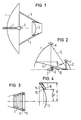
- FIG. 1 shows a schematic side view of a rotationally symmetrical two-directional microwave directional antenna with a main reflector 1, a subreflector 2 that illuminates the main reflector 1 and is concavely curved according to the Gregory principle, and one with its opening between the apex of the main reflector 1 and the apex of the sub-reflector 2 arranged primary horn radiator 3.
- the primary horn radiator 3 is fed via a hollow line 4, which is led out through an apex opening of the main reflector 1 to the rear.
- the sub-reflector 2 is held by four X-shaped straight supports 5, the base points of which lie in the region of the edge of the main reflector 1.
- the sub-reflector 2 and the supports 5 are necessarily in the beam path of the main reflector 1 and thereby cause interference, which is reflected in a deterioration of the side lobe characteristics. If the primary horn 3 is still relatively close to the subreflector 2, additional disturbances are to be expected, which do not allow the secondary lobe specifications to be met, at least in the wide-angle range.
- a beam from the primary horn 3 to the edge 7 of the sub-reflector 2 with 10 a beam from the sub-reflector 2 to the edge 6 of the primary horn 3, with 11
- Beam from the subreflector 2 to the main reflector 1 and 12 denotes a beam from the subreflector 2 to the edge 8 of the main reflector 1.
- the beam 9 describes the radiation and diffraction effects at the subreflector 2.
- the beam 12 describes the radiation and the edge diffraction at the main reflector 1.
- the beam 11 describes the reflection from the main reflector 1 onto the subreflector edge 7.
- the dominant source of interference is the secondary scattered radiation from the subreflector 2 illuminated primary horn 3, which is caused by the beam 10.
- the main reflector 1 and the subreflector 2 are designed according to the invention so that the subreflector stray field indicated by the beam 10 towards the edge 6 of the primary horn emitter has a certain low radiation level of, for example, -8 dBi, the subreflector scatter field indicated by the beam 11 in the direction of the projection of the sub-reflector edge 7 in the main reflector 1 does not exceed a certain low radiation level of, for example, -6 dBi, and the sub-reflector stray field indicated by the beam 12 in the direction of the main reflector edge 8 does not exceed a certain low radiation level of, for example, -10 dBi.
- Fig. 3 shows a longitudinal sectional view of a grooved primary horn 3, which is covered at the front at its edge 6 at the opening with a ring made of absorber material 13.
- the absorber material 13 is graphitized polyurethane foam with a weatherproof impregnated textile fabric skin or a weatherproof, absorbent rubber mat.
- Fig. 4 shows a subreflector 2, which is covered all around in an edge zone by absorber material 15.
- the edge zone covered by the absorber material 15 extends over about a third of the sub-reflector radius R, starting from the edge.
- the edge zone of the sub-reflector 2 is milled out.
- the absorber material 15 with a suitable contour profile 16 is inserted into the cutout 14.
- a smooth surface profile is obtained, which has more favorable properties with regard to snow and ice build-up as well as contamination than an absorber that was subsequently glued on, e.g. a rubber mat.
Landscapes
- Aerials With Secondary Devices (AREA)
Claims (5)
- Antenne directive à micro-ondes à deux réflecteurs et à symétrie de révolution, avec de faibles niveaux des lobes secondaires du diagramme de rayonnement dans des zones spatiales prédéterminées moyennant l'utilisation d'un réflecteur principal (1), d'un réflecteur secondaire (2) éclairant le réflecteur principal et influençant défavorablement l'affaiblissement des lobes secondaires, et un émetteur primaire en cornet (3), dont l'ouverture est disposée entre le sommet du réflecteur principal et le sommet du réflecteur secondaire, le champ de l'ouverture étant agencé en forme de tore, en sorte qu'il en résulte une diminution aussi bien en direction du bord (8) du réflecteur principal que du bord (7) du réflecteur secondaire, à partir d'un maximum situé entre ces deux bords,
caractérisée par le fait que
le réflecteur secondaire (2) est cintré avec une forme concave selon le principe Gregory, que le bord (6) de l'ouverture de l'émetteur primaire en cornet (3) est recouvert par un matériau absorbant (13) et/ou que le réflecteur secondaire (2) est recouvert sur son pourtour par un matériau absorbant (15) dans une zone marginale qui s'étend approximativement sur un tiers du rayon (R) du réflecteur secondaire, à partir du bord (7), de sorte que le champ de fuite du réflecteur secondaire ne dépasse pas un faible niveau déterminé de rayonnement égal par exemple à -8 dBi en direction du bord (6) de l'émetteur primaire en cornet (3), à un faible niveau déterminé de rayonnement égal à au moins environ -6 dBi en direction de la projection du bord (7) du réflecteur secondaire dans le réflecteur principal (1) et un faible niveau déterminé de rayonnement d'environ -10 dBi en direction du bord (8) du réflecteur principal, ce qui conduit à une variation de l'amplitude du champ de l'ouverture, qui possède un maximum situé approximativement au milieu entre le bord du réflecteur secondaire et le bord du réflecteur principal et diminue progressivement pour tomber à un niveau de -15 dB ou plus tant en direction du bord du réflecteur principal que du bord de réflecteur secondaire, cette variation d'amplitude étant choisie de manière que les premiers lobes secondaires se situent entre -11 et -14 dB et que les second et les autres lobes secondaires du diagramme de rayonnement se situent au-dessous d'une courbe A = (Z - 25 log ϑ) avec Z ≃ 29, A étant le niveau du diagramme de rayonnement en dBi et ϑ l'angle du diagramme par rapport à l'axe de symétrie de l'antenne. - Antenne directive suivant la revendication 1, caractérisée par le fait qu'il est prévu, comme matériau absorbant (13), pour le bord (6) de l'émetteur primaire en cornet (3), de la mousse de polyuréthane graphitée possédant un revêtement de tissu textile imprégné de manière à résister aux intempéries.
- Antenne directive suivant la revendication 1, caractérisée par le fait qu'il est prévu, comme matériau absorbant (13), pour le bord (6) de l'émetteur primaire en cornet (3), un matériau formé d'un matelas de caoutchouc résistant aux intempéries.
- Antenne directive suivant la revendication 1, caractérisée par le fait que la zone marginale du réflecteur secondaire (2) est fraisée et qu'un matériau absorbant (15) possédant un contour de forme adaptée (16) est inséré dans le fraisage (14).
- Antenne directive suivant l'une des revendications 1 et 2, caractérisée par le fait que pour la zone marginale du réflecteur secondaire (2), il est prévu un matériau absorbant (15) pouvant être traité mécaniquement, par exemple une ferrite.
Priority Applications (1)
| Application Number | Priority Date | Filing Date | Title |
|---|---|---|---|
| AT88104199T ATE77514T1 (de) | 1987-03-19 | 1988-03-16 | Zweireflektor-microwellen-richtantenne. |
Applications Claiming Priority (2)
| Application Number | Priority Date | Filing Date | Title |
|---|---|---|---|
| DE3709040 | 1987-03-19 | ||
| DE3709040 | 1987-03-19 |
Publications (2)
| Publication Number | Publication Date |
|---|---|
| EP0284897A1 EP0284897A1 (fr) | 1988-10-05 |
| EP0284897B1 true EP0284897B1 (fr) | 1992-06-17 |
Family
ID=6323520
Family Applications (1)
| Application Number | Title | Priority Date | Filing Date |
|---|---|---|---|
| EP88104199A Expired - Lifetime EP0284897B1 (fr) | 1987-03-19 | 1988-03-16 | Antenne directive micro-ondes à deux réflecteurs |
Country Status (3)
| Country | Link |
|---|---|
| EP (1) | EP0284897B1 (fr) |
| AT (1) | ATE77514T1 (fr) |
| DE (1) | DE3872016D1 (fr) |
Cited By (1)
| Publication number | Priority date | Publication date | Assignee | Title |
|---|---|---|---|---|
| WO2001048867A1 (fr) * | 1999-12-28 | 2001-07-05 | Telefonaktiebolaget Lm Ericsson (Publ) | Dispositif relatif a des antennes a reflecteur |
Families Citing this family (4)
| Publication number | Priority date | Publication date | Assignee | Title |
|---|---|---|---|---|
| DE4140841A1 (de) * | 1990-12-20 | 1992-07-02 | Siemens Ag | Mikrowellen-richtfunkantenne |
| DE4200755C2 (de) * | 1992-01-14 | 1997-01-16 | Siemens Ag | Zweireflektor-Mikrowellen-Richtantenne |
| US6603437B2 (en) | 2001-02-13 | 2003-08-05 | Raytheon Company | High efficiency low sidelobe dual reflector antenna |
| CN108808250B (zh) * | 2018-06-08 | 2020-06-16 | 西安电子科技大学 | 基于超表面的凸面共形格里高利天线 |
Family Cites Families (3)
| Publication number | Priority date | Publication date | Assignee | Title |
|---|---|---|---|---|
| US3611393A (en) * | 1970-04-27 | 1971-10-05 | Bell Telephone Labor Inc | Parabolic tripod feed support for parabolic dish antenna |
| FR2304192A1 (fr) * | 1975-03-14 | 1976-10-08 | Thomson Csf | Antenne a reduction selective de gain |
| EP0136817A1 (fr) * | 1983-09-06 | 1985-04-10 | Andrew Corporation | Antenne de type Gregory aux lobes secondaires faibles |
-
1988
- 1988-03-16 AT AT88104199T patent/ATE77514T1/de not_active IP Right Cessation
- 1988-03-16 DE DE8888104199T patent/DE3872016D1/de not_active Expired - Fee Related
- 1988-03-16 EP EP88104199A patent/EP0284897B1/fr not_active Expired - Lifetime
Cited By (1)
| Publication number | Priority date | Publication date | Assignee | Title |
|---|---|---|---|---|
| WO2001048867A1 (fr) * | 1999-12-28 | 2001-07-05 | Telefonaktiebolaget Lm Ericsson (Publ) | Dispositif relatif a des antennes a reflecteur |
Also Published As
| Publication number | Publication date |
|---|---|
| DE3872016D1 (de) | 1992-07-23 |
| ATE77514T1 (de) | 1992-07-15 |
| EP0284897A1 (fr) | 1988-10-05 |
Similar Documents
| Publication | Publication Date | Title |
|---|---|---|
| DE69728603T2 (de) | Linsenantenne mit verbesserter dielektrischer Linse zur Reduzierung von durch intern reflektierte Wellen verursachten Störungen | |
| DE60103653T2 (de) | Verbesserung des erregers für sender/empfänger elektromagnetischer wellen in einer mehrreflektor-antenne | |
| DE102009054526B4 (de) | Dielektrisch belastete Antenne mit innerem Hohlraumabschnitt | |
| DE4026432C2 (de) | Radialleitungsschlitzantenne | |
| EP0896749B1 (fr) | Ensemble antenne hyperfrequence pour systeme radar de vehicule a moteur | |
| DE60107939T2 (de) | Reflektorantenne mit gemeinsamer apertur und verbessertem zuführungsentwurf | |
| DE602004000083T2 (de) | Speise für Reflektorantenne | |
| DE3536581A1 (de) | Doppeltes gitter-antennenreflektorsystem und verfahren zu seiner herstellung | |
| DE112021002225T5 (de) | Dielektrische Linse und elektromagnetische Vorrichtung mit derselben | |
| DE10339675A1 (de) | Multiband-Ringfokus-Doppelreflektorantennensystem | |
| DE602005001108T2 (de) | Antennenanordnung mit Dipolen und vier Metallstäben | |
| DE3218690C1 (de) | Bikonische Rundstrahlantenne | |
| DE2812903C2 (de) | Antenne mit einem Primärstrahler, einem Hauptreflektor und einem zu diesem exzentrischen Hilfsreflektor | |
| DE2610506A1 (de) | Antenne | |
| EP0284897B1 (fr) | Antenne directive micro-ondes à deux réflecteurs | |
| EP0679318B1 (fr) | Ensemble antenne radio pour la bande d'ondes decimetriques monte sur vehicules | |
| DE2441638C3 (de) | Breitbandantenne mit einer in der Nähe eines Reflektors angeordneten Spirale | |
| DE102010003457A1 (de) | Leckwellenantenne | |
| EP0284883B1 (fr) | Antenne directive micro-ondes à deux réflecteurs | |
| EP0021193A1 (fr) | Système d'antennes combiné | |
| DE2342904C3 (de) | Richtantenne mit niedrigen Nebenzipfeln | |
| DE4336840C1 (de) | Abdeckung für Radarantennen | |
| DE4200755C2 (de) | Zweireflektor-Mikrowellen-Richtantenne | |
| DE602006000193T2 (de) | Abstrahlendes Koaxialkabel | |
| DE102014112485B4 (de) | Hornstrahlerantenne mit verringerter verkopplung zwischen antennenelementen |
Legal Events
| Date | Code | Title | Description |
|---|---|---|---|
| PUAI | Public reference made under article 153(3) epc to a published international application that has entered the european phase |
Free format text: ORIGINAL CODE: 0009012 |
|
| AK | Designated contracting states |
Kind code of ref document: A1 Designated state(s): AT BE CH DE ES FR GB GR IT LI LU NL SE |
|
| 17P | Request for examination filed |
Effective date: 19890126 |
|
| 17Q | First examination report despatched |
Effective date: 19901122 |
|
| GRAA | (expected) grant |
Free format text: ORIGINAL CODE: 0009210 |
|
| AK | Designated contracting states |
Kind code of ref document: B1 Designated state(s): AT BE CH DE ES FR GB GR IT LI LU NL SE |
|
| PG25 | Lapsed in a contracting state [announced via postgrant information from national office to epo] |
Ref country code: SE Effective date: 19920617 Ref country code: GR Free format text: LAPSE BECAUSE OF FAILURE TO SUBMIT A TRANSLATION OF THE DESCRIPTION OR TO PAY THE FEE WITHIN THE PRESCRIBED TIME-LIMIT Effective date: 19920617 Ref country code: FR Effective date: 19920617 Ref country code: ES Free format text: THE PATENT HAS BEEN ANNULLED BY A DECISION OF A NATIONAL AUTHORITY Effective date: 19920617 Ref country code: BE Effective date: 19920617 |
|
| REF | Corresponds to: |
Ref document number: 77514 Country of ref document: AT Date of ref document: 19920715 Kind code of ref document: T |
|
| REF | Corresponds to: |
Ref document number: 3872016 Country of ref document: DE Date of ref document: 19920723 |
|
| ITF | It: translation for a ep patent filed |
Owner name: STUDIO JAUMANN |
|
| GBT | Gb: translation of ep patent filed (gb section 77(6)(a)/1977) | ||
| EN | Fr: translation not filed | ||
| PG25 | Lapsed in a contracting state [announced via postgrant information from national office to epo] |
Ref country code: LU Free format text: LAPSE BECAUSE OF NON-PAYMENT OF DUE FEES Effective date: 19930331 |
|
| PLBE | No opposition filed within time limit |
Free format text: ORIGINAL CODE: 0009261 |
|
| STAA | Information on the status of an ep patent application or granted ep patent |
Free format text: STATUS: NO OPPOSITION FILED WITHIN TIME LIMIT |
|
| 26N | No opposition filed | ||
| PGFP | Annual fee paid to national office [announced via postgrant information from national office to epo] |
Ref country code: GB Payment date: 19940218 Year of fee payment: 7 |
|
| PGFP | Annual fee paid to national office [announced via postgrant information from national office to epo] |
Ref country code: AT Payment date: 19940223 Year of fee payment: 7 |
|
| PGFP | Annual fee paid to national office [announced via postgrant information from national office to epo] |
Ref country code: NL Payment date: 19940331 Year of fee payment: 7 |
|
| PGFP | Annual fee paid to national office [announced via postgrant information from national office to epo] |
Ref country code: CH Payment date: 19940617 Year of fee payment: 7 |
|
| PG25 | Lapsed in a contracting state [announced via postgrant information from national office to epo] |
Ref country code: GB Effective date: 19950316 Ref country code: AT Effective date: 19950316 |
|
| PG25 | Lapsed in a contracting state [announced via postgrant information from national office to epo] |
Ref country code: LI Effective date: 19950331 Ref country code: CH Effective date: 19950331 |
|
| PG25 | Lapsed in a contracting state [announced via postgrant information from national office to epo] |
Ref country code: NL Effective date: 19951001 |
|
| GBPC | Gb: european patent ceased through non-payment of renewal fee |
Effective date: 19950316 |
|
| REG | Reference to a national code |
Ref country code: CH Ref legal event code: PL |
|
| NLV4 | Nl: lapsed or anulled due to non-payment of the annual fee |
Effective date: 19951001 |
|
| PGFP | Annual fee paid to national office [announced via postgrant information from national office to epo] |
Ref country code: DE Payment date: 19970521 Year of fee payment: 10 |
|
| PG25 | Lapsed in a contracting state [announced via postgrant information from national office to epo] |
Ref country code: DE Free format text: LAPSE BECAUSE OF NON-PAYMENT OF DUE FEES Effective date: 19981201 |
|
| PG25 | Lapsed in a contracting state [announced via postgrant information from national office to epo] |
Ref country code: IT Free format text: LAPSE BECAUSE OF NON-PAYMENT OF DUE FEES;WARNING: LAPSES OF ITALIAN PATENTS WITH EFFECTIVE DATE BEFORE 2007 MAY HAVE OCCURRED AT ANY TIME BEFORE 2007. THE CORRECT EFFECTIVE DATE MAY BE DIFFERENT FROM THE ONE RECORDED. Effective date: 20050316 |