EP0284746A1 - Hydraulisches Pumpenaggregat - Google Patents
Hydraulisches Pumpenaggregat Download PDFInfo
- Publication number
- EP0284746A1 EP0284746A1 EP19880101959 EP88101959A EP0284746A1 EP 0284746 A1 EP0284746 A1 EP 0284746A1 EP 19880101959 EP19880101959 EP 19880101959 EP 88101959 A EP88101959 A EP 88101959A EP 0284746 A1 EP0284746 A1 EP 0284746A1
- Authority
- EP
- European Patent Office
- Prior art keywords
- stator
- hydraulic pump
- housing
- pump unit
- unit according
- Prior art date
- Legal status (The legal status is an assumption and is not a legal conclusion. Google has not performed a legal analysis and makes no representation as to the accuracy of the status listed.)
- Granted
Links
Images
Classifications
-
- H—ELECTRICITY
- H02—GENERATION; CONVERSION OR DISTRIBUTION OF ELECTRIC POWER
- H02K—DYNAMO-ELECTRIC MACHINES
- H02K9/00—Arrangements for cooling or ventilating
- H02K9/22—Arrangements for cooling or ventilating by solid heat conducting material embedded in, or arranged in contact with, the stator or rotor, e.g. heat bridges
- H02K9/223—Heat bridges
-
- F—MECHANICAL ENGINEERING; LIGHTING; HEATING; WEAPONS; BLASTING
- F04—POSITIVE - DISPLACEMENT MACHINES FOR LIQUIDS; PUMPS FOR LIQUIDS OR ELASTIC FLUIDS
- F04B—POSITIVE-DISPLACEMENT MACHINES FOR LIQUIDS; PUMPS
- F04B53/00—Component parts, details or accessories not provided for in, or of interest apart from, groups F04B1/00 - F04B23/00 or F04B39/00 - F04B47/00
- F04B53/08—Cooling; Heating; Preventing freezing
-
- H—ELECTRICITY
- H02—GENERATION; CONVERSION OR DISTRIBUTION OF ELECTRIC POWER
- H02K—DYNAMO-ELECTRIC MACHINES
- H02K9/00—Arrangements for cooling or ventilating
- H02K9/14—Arrangements for cooling or ventilating wherein gaseous cooling medium circulates between the machine casing and a surrounding mantle
-
- H—ELECTRICITY
- H02—GENERATION; CONVERSION OR DISTRIBUTION OF ELECTRIC POWER
- H02K—DYNAMO-ELECTRIC MACHINES
- H02K9/00—Arrangements for cooling or ventilating
- H02K9/19—Arrangements for cooling or ventilating for machines with closed casing and closed-circuit cooling using a liquid cooling medium, e.g. oil
Definitions
- the application relates to a hydraulic pump unit of the type specified in the preamble of claim 1.
- the object of the invention is therefore to create a hydraulic pump unit of the type mentioned, in which a long service life for the oil is achieved despite continuous operation.
- the increased heat generated at the upper end of the stator is specifically transported into the positively cooled upper part of the housing, where the best cooling effect is achieved.
- the heat throughput is increased and a forced upward heat transport direction is achieved.
- the heat transfer body partially shields the stator end face and the inner wall of the housing against direct contact with the oil there from where the high temperature, which could be harmful to the oil, is present. In this critical area, the oil is relieved of heat dissipation, which guarantees a long service life for the oil even during continuous operation.
- DE-OS 14 88 575 an annular heat transfer body for radial heat dissipation from the stator to the middle area of the housing, from DE-AS 11 23 038 a solid position securing ring at the end of the stator and from DE-AS 15 38 819 one consisting of a laminated core assembly Heat transfer body known.
- the known heat transfer bodies serve for the direct protection of the stators or winding heads against overheating, and not for overheating protection of a medium directly contacting stators or winding heads. None of these references gives an indication of using the heat transfer body as overheating protection of a liquid medium touching the stator.
- stator need only be pressed into the lower part over a short axial path, for example with the help the sleeve.
- the sleeve itself then serves as a centering attachment for attaching the upper part. Nevertheless, the sleeve acts as a thermal bridge during operation of the pump unit, which specifically contributes to the fact that the heat is transported upwards.
- sealing problem in the aforementioned, divided construction is advantageously solved according to claim 4 or claim 5.
- the sealing elements form throttling points in the heat transport, their effect on the targeted heat transport upwards is negligible.
- the assembly of the electric motor or the stator in the receptacle is particularly simple.
- the collar of the receptacle, which forms the heat transfer body, also serves as a centering approach for plugging on the upper housing part.
- a very effective and upward heat transfer from the stator to the external cooling fins is achieved in this way.
- the collar leads to the advantage of a larger inner diameter of the upper housing part for a given size of the stator. Due to the larger inner diameter of the upper part, the housing can be built lower with the same capacity of the oil storage space above the electric motor, while the cooling fan is more powerful thanks to the larger diameter.
- the cooling fan moves closer to the stator, which improves the overall cooling performance.
- the lower part Since the cooling effect of the lower housing part is negligible compared to the cooling effect of the upper housing part, the lower part does not need any outer ribs, but comes with a simple and inexpensive to manufacture design, which is not designed with regard to cooling but only to secure the position of the electric motor and the hydraulic pump elements.
- the feature of claim 7 is also expedient because axial heat transfer into the upper housing part can also be achieved via the shoulder.
- the feature of claim 8 is also advantageous because a high heat throughput is achieved via the generous cross section of the heat transfer body and, in addition, the inside diameter of the upper housing part is increased to reduce the overall height of the housing.
- the feature of claim 9 is also favorable, because in this area of the pump unit a few, generously dimensioned oil channels ensure a favorable oil exchange between the upper storage space and the lower space of the pump unit. Finally, it is also favorable in this embodiment that almost all of the heat transferred from the stator to the receptacle is not transported directly to the inner wall of the lower housing part but specifically to the upper housing part, where - as mentioned - the cooling effect is best.
- the embodiment according to claim 10 is also expedient because the collar forming the heat transfer body protrudes considerably into the upper housing part, so that a high heat throughput to the upper housing part is achieved in the contact area between the collar and the inner wall of the upper housing part.
- a lightweight and powerful Pump unit is also achieved with the feature of claim 11.
- either die cast parts or drawn parts can be used for the components of the housing, which are very precise and inexpensive to manufacture in series production.
- housings of larger electric motors are commercially available and do not need any special post-processing in order to be usable as the upper housing part for the pump unit. Especially with larger sizes of the pump unit, it is expensive to use drawn light metal pipes, while cast electric motor housings of large series can be obtained inexpensively.
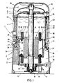
- the housing 2 is filled with oil 7 on the inside, the mirror of which can extend to the cover 5.
- An electric motor 8 of the open type is mounted in the housing 2 and drives a hydraulic part 9 in the lower part 3.
- a cooling fan 10 is mounted on top of the cover 5.
- the electric motor 8 consists of a stator 11 with a stator or excitation winding 12 and a rotor 13 rotatable in the stator 11 with its rotor shaft 14.
- the rotor shaft 14 is extended at the top through the cover 5 and drives a fan wheel 15 of the cooling fan 10 there
- the cooling fan 10 is covered by a protective cover 16 which at the same time serves to guide the cooling air (dashed arrow 17) along the outside of the upper housing part 4.
- Hydraulic pump elements 19 are provided in the hydraulic part 9, which are driven by the rotor shaft 14 via an eccentric 18 and convey the oil 17 to an outlet 20 in the lower housing part 3.
- Inner ribs 21 are formed in the lower housing part 3, to which a bearing plate 22 for a bearing 23 of the rotor shaft 14 is fastened.
- a receptacle 24 for the stator 11 of the electric motor is formed in the lower part 3, which is formed by an upstanding collar 25 and a lower part 26.
- the radial strength S thicker as the part 26 formed collar 25 is offset via a shoulder 27 from the outside of the lower part 3.
- a plurality of oil channels 28 run in the collar 25, which establish a flow connection from a storage chamber 30 above the electric motor 8 to the pump chamber 31 below.
- the upper housing part 4 has a relatively thin housing wall 32 with external cooling fins 33.
- the upper part 4 is slid over the collar 25 with a sliding fit and its end face 34 is blunt on the shoulder 27. Sealing elements 29 are provided in the connection area of the housing parts 3 and 4.
- the inner wall of the upper housing part 4, designated 35 fits snugly against the outer wall of the collar 25.
- Line 36 indicates the processing of inner wall 35 for a precise fit.
- An oil inspection pipe 38 connects, visible from the outside, the storage chamber 30 to the pump scanner 31. The oil is returned to the storage chamber 30 via an inlet 39 in the upper cover 5 the upper end face 40 of the collar 25 is approximately aligned with the upper end face 41 of the stator 11.
- the collar 25 forms a heat transfer body W, with which heat generated in the stator 11 is effectively transported to the upper housing part 4, from whose cooling fins 33, thanks to the cooling air flow 17, this heat is rapidly dissipated.
- the heat flow is indicated by dash-dotted arrows 44.
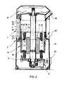
- the housing 2 ⁇ from the lower part 3 ⁇ and the upper part 4 ⁇ supports the electric motor 8 in a receptacle 24 ⁇ in the lower part 3 ⁇ , in which the collar 25 ⁇ is thinner than the collar 25 in the embodiment of FIG. 1. Furthermore, the stator 11 of the electric motor shorter than in the embodiment of Fig. 1 and so far pressed into the receptacle 24 ⁇ that the front end 40 of the stator 11 is approximately at the level of the shoulder 27 ⁇ . The collar 25 ⁇ protrudes beyond the stator winding 12 so that its front end 40 ⁇ is relatively far up in the upper housing part 4 ⁇ .
- the collar 25 ⁇ here again forms a heat transfer body W, with which the heat introduced into the receptacle 24 ⁇ by the stator 11 is effectively carried out into the housing wall 32 of the upper part 4 von and from there via the cooling fins 33 to the outside where the cooling fan 10 is particularly effective is.
- the dash-dotted arrows 44 indicate the heat transfer path.
- the housing wall 32 of the upper part 4 ⁇ is tapered at 42.
- a correspondingly inclined counter surface 43 is provided in the transition from the flange 37 ⁇ to the collar 25 ⁇ . Part of the heat introduced into the receptacle 24 ⁇ is therefore also conducted into the upper housing part via the adjoining surfaces 42, 43.
- the housing 2 ⁇ consists of a continuous, drawn tube with an inner wall 32 ⁇ and the outer cooling fins 33.
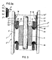
- the stator 11 is pressed so far into the housing 2 ⁇ that its upper front end 41 to lie on the level of a shoulder 45 comes and he sits on a stop 46.
- the shoulder 45 serves to facilitate the pressing in of the stator 11.
- the heat transfer body W used here is an annular sleeve 47, which rests with its lower end 48 on the end 41 of the stator 11 and at the same time abuts the inner wall of the housing wall 32 ⁇ .
- the sleeve 47 also serves to secure the position of the stator 11.
- the heat generated in the stator 11 is not only transferred directly to the housing wall 32 ⁇ , but also upwards via the heat transfer body W.
- the housing 2 ′′′ is divided into two at the level of a dividing joint 50, so that a lower part 3 ⁇ and an upper part 4 ⁇ are formed, both of which are drawn tubes with outer ribs 33.
- the sleeve 47 ⁇ is equipped with two sealing elements 51, which seal on both sides of the dividing joint 50.
- the sleeve 47 ⁇ is optionally provided, like the sleeve 47, with a thickening 49 on the underside in order to improve the heat transfer from the front end 41 of the stator to the sleeve 47 ⁇ .
- the dividing joint 50 could also be formed according to FIG. 3a with gradations 52 and 53 between the lower part 3 4 and the upper part 4 ′′′, so that a seal 54 can be introduced in this area.
- the sleeve 47 corresponds to that of the right half of FIG. 3.
- the rotor shaft can be hollow, for example.
Abstract
Description
- Die Anmeldung betrifft ein hydraulisches Pumpenaggregat der in Oberbegriff des Patentanspruchs 1 angegebenen Art.
- Bei einem aus der DE-OS 35 13 472 bekannten Pumpenaggregat für Dauerbetrieb besteht die Gefahr, daß sich infolge des gedrosselten Wärmetransports zum zwangsgekühlten Gehäuseoberteil das obere Ende des Stators auf für den Elektromotor unschädliche, für das Öl im Ölbad jedoch schädliche Temperatur erhitzt, die die Standzeit des Öls beträchtlich verkürzt.
- Der Erfinding liegt deshalb die Aufgabe zugrunde, ein hydraulisches Pumpenaggregat der eingangs genannten Art zu schaffen, bei dem trotz Dauerbetriebs eine lange Standzeit für das Öl erreicht wird.
- Die gestellte Aufgabe wird erfindungsgemäß mit den im kennzeichnenden Teil des Patentanspruchs 1 angegebenen Merkmalen gelöst.
- Über die vom Wärmeübertragungskörper gebildete Wärmebrücke wird die am oberen Statorende verstärkt entstehende Wärme gezielt in den zwangsgekühlten Gehäuseoberteil transportiert, an dem die beste Kühlwirkung gegeben ist. Dadurch wird der Wärmedurchsatz gesteigert und eine erzwungene Wärmetransportrichtung nach oben erreicht. Der Wärmeübertragungskörper schirmt zum Teil die Statorendfläche und die Innenwand des Gehäuses gegen einen direkten Kontakt mit dem Öl dort ab, wo die gegebenenfalls für das Öl schädliche hohe Temperatur vorläge. Das Öl wird in diesem kritischen Bereich bezüglich der Wärmeabfuhr entlastet, wodurch auch bei Dauerbetrieb eine lange Standzeit für das Öl gewährleistet ist.
- Es sind zwar aus der DE-OS 14 88 575 ein ringförmiger Wärmeübertragungskörper zur radialen Wärmeableitung vom Stator an den Gehäusemittelbereich, aus der DE-AS 11 23 038 ein massiver Lagesicherungsring am Statorende und aus der DE-AS 15 38 819 ein aus einem Blechlamellenpaket bestehender Wärmeübertragungskörper bekannt. Jedoch dienen die bekannten Wärmeübertragungskörper zum direkten Schutz der Statoren bzw. Wikkelköpfe gegen Überhitzung, und nicht zum Überhitzungschutz eines Statoren bzw. Wickelköpfe direkt berührenden Mediums. Einen Hinweis, den Wärmeübertragungskörper als Überhitzungsschutz eines den Stator berührenden flüssigen Mediums zu benutzen, gibt keine dieser Entgegenhaltungen.
- Eine zweckmäßige Ausführungsform, bei der das Gehäuse ein durchgehender, beidendig durch Deckel verschlossener Rohrkörper ist, geht aus Anspruch 2 hervor. Im stumpfen Berührungsbereich zwischen der Hülse und dem Stirnende des Stators wird die Wärme wirkungsvoll übertragen und nach oben verlagert, wo die Kühlwirkung besonders gut ist. Gleichzeitig wird auch vom Stator direkt Wärme an das Gehäuse übertragen und außen über die Kühlrippen abgeführt.
- Eine in montagetechnischer Sicht verbesserte Ausführungsform geht aus Anspruch 3 hervor. Der Stator braucht nur über einen kurzen axialen Weg in den Unterteil eingepreßt zu werden, beispielsweise mit Hilfe der Hülse. Die Hülse selbst dient dann als Zentrieransatz zum Aufstecken des Oberteils. Trotzdem wirkt die Hülse beim Betrieb des Pumpenaggregates als Wärmebrücke, die gezielt dazu beiträgt, daß die Wärme nach oben transportiert wird.
- Das Dichtproblem bei der vorgenannten, geteilten Bauweise wird zweckmäßigerweise gemäß Anspruch 4 oder Anspruch 5 gelöst. Obwohl die Dichtelemente Drosselstellen im Wärmetransport bilden, ist ihre Wirkung auf den gezielten Wärmetransport nach oben vernachlässigbar.
- Eine weitere, zweckmäßige Ausführungsform geht aus Anspruch 6 hervor. Die Montage des Elektromotors bzw. des Stators in der Aufnahme ist besonders einfach. Der Kragen der Aufnahme, der den Wärmeübertragungskörper bildet, dient gleichzeitig als Zentrieransatz zum Aufstekken des Gehäuseoberteils. In zusammengebautem Zustand des Gehäuses wird auf diese Weise ein sehr wirkungsvoller und nach oben gerichteter Wärmetransport vom Stator zu den außenliegenden Kühlrippen erreicht. Dazu kommt, daß der Kragen bei gegebener Baugröße des Stators zu dem Vorteil eines größeren Innendurchmessers des Gehäuseoberteils führt. Aufgrund des größeren Innendurchmessers des Oberteils läßt sich bei gleichem Fassungsvermögen des oberhalb des Elektromotors vorliegenden Speicherraums für das Öl das Gehäuse niedriger bauen, während der Kühllüfter dank des größeren Durchmessers leistungsfähiger ausfällt. Zudem rückt der Kühllüfter näher an den Stator heran, wodurch die Kühlleistung insgesamt verbessert wird. Da die Kühlwirkung beim Gehäuseunterteil im Vergleich zur Kühlwirkung beim Gehäuseoberteil vernachlässigbar ist, benötigt der Unterteil keine Außenrippen, sondern kommt mit einer einfachen und preiswert herstellbaren Bauform aus, die nicht im Hinblick auf die Kühlung sondern nur auf die Lagesicherung des Elektromotors und der hydraulischen Pumpenelemente konzipiert wird.
- Zweckmäßig ist ferner das Merkmal von Anspruch 7, weil über die Schulter auch ein axialer Wärmetransport in den Gehäuseoberteil erzielbar.
- Günstig ist ferner das Merkmal von Anspruch 8, weil über den großzügigen Querschnitt des Wärmeübertragungskörpers ein hoher Wärmedurchsatz erreicht wird und zudem zum Verringern der Bauhöhe des Gehäuses der Innendurchmesser des Gehäuseoberteils vergrößert wird.
- Günstig ist ferner das Merkmal von Anspruch 9, weil in diesem Bereich des Pumpenaggregats wenige, großzügig bemessene Ölkanäle für einen günstigen Ölaustausch zwischen dem obenliegenden Speicherraum und dem untenliegenden Raum des Pumpenaggregats sorgen. Günstig ist bei dieser Ausführungsform schließlich auch, daß nahezu die gesamte vom Stator auf die Aufnahme übertragene Wärme nicht direkt zur Innenwand des Gehäuseunterteils sondern gezielt zum Gehäuseoberteil transportiert wird, wo - wie erwähnt - die Kühlwirkung am besten ist.
- Zweckmäßig ist ferner die Ausführungsform gemäß Anspruch 10, weil der den Wärmeübertragungskörper bildende Kragen beträchtlich in den Gehäuseoberteil hinaufragt, so daß im Kontaktbereich zwischen dem Kragen und der Innenwand des Gehäuseoberteils ein hoher Wärmedurchsatz zum Gehäuseoberteil erreicht wird.
- Eine leichtgewichtiges und leistungsfähiges Pumpenaggregat wird ferner mit dem Merkmal von Anspruch 11 erzielt. Dabei können für die Komponenten des Gehäuses entweder Druckgußteile oder gezogene Teile verwendet werden, die sehr maßgenau und in der Serienfertigung kostengünstig herstellbar sind.
- Eine weitere, hinsichtlich der Herstellungskosten und des Aufwandes zweckmäßige Ausführungsform geht schließlich aus Anspruch 12 hervor. Gehäuse größerer Elektromotoren sind im Handel erhältlich und brauchen keine spezielle Nachbearbeitung, um als Gehäuseoberteil für das Pumpenaggregat nutzbar zu sein. Gerade bei größeren Baugrößen des Pumpenaggregats ist es nämlich teuer, gezogenen Leichtmetall-Rohre zu verwenden, während gegossene Elektromotoren-Gehäuse großer Bauserien preisgünstig zu erhalten sind.
- Anhand der Zeichnung werden Ausführungsformen des Erfindungsgegenstandes erläutert. Es zeigen:
- Fig. 1 einen Längsschnitt durch eine erste Ausführungsform eines hydraulischen Pumpenaggregats,
- Fig. 2 einen Längsschnitt durch eine zweite Ausführungsform,
- Fig. 3 jeweils eine rechte und eine linke Hälfte einer weiteren Ausführungsform, im Teillängsschnitt, und
- Fig. 3a eine Detailvariante zu der linken Hälfte von Fig. 3.
- Eine hydraulisches Pumpenaggregat 1 gemäß Fig. 1, das zum Dauerbetrieb an der Leistungsgrenze seines Elektromotors geeignet ist, besitzt ein Gehäuse 2 mit einem ständerförmigen Unterteil 3 und einem außenverrippten Oberteil 4. Deckel 5 und 6 schließen das Gehäuse ab. Das Gehäuse 2 ist innen mit Öl 7 gefüllt, dessen Spiegel bis zum Deckel 5 reichen kann.
- Im Gehäuse 2 ist ein Elektromotor 8 der offenen Bauart gelagert, der einen Hydraulikteil 9 im Unterteil 3 treibt. Oben auf dem Deckel 5 ist ein Kühlgebläse 10 gelagert.
- Der Elektromotor 8 besteht aus einem Stator 11 mit einer Stator- oder Erregerwicklung 12 sowie aus einem im Stator 11 drehbaren Rotor 13, mit seiner Rotorwelle 14. Die Rotorwelle 14 ist oben durch den Deckel 5 hindurch verlängert und treibt dort ein Lüfterrad 15 des Kühlgebläses 10. Das Kühlgebläse 10 wird durch einen Schutzdeckel 16 abgedeckt, der gleichzeitig zur Kühluftführung (strichlierter Pfeil 17) entlang der Außenseite des Gehäuseoberteils 4 dient.
- Im Hydraulikteil 9 sind hydraulische Pumpenelemente 19 vorgesehen, die über einen Exzenter 18 von der Rotorwelle 14 angetrieben werden und das Öl 17 zu einem Auslaß 20 im Gehäuseunterteil 3 fördern. Im Gehäuseunterteil 3 sind innere Rippen 21 eingeformt, an denen eine Lagerplatte 22 für ein Lager 23 der Rotorwelle 14 befestigt ist.
- Ferner ist in den Unterteil 3 eine Aufnahme 24 für den Stator 11 des Elektromotors eingeformt, die durch einen nach oben stehenden Kragen 25 und einen unteren Teil 26 gebildet wird. Der in seiner radialen Stärke S dicker als der Teil 26 ausgebildete Kragen 25 ist über eine Schulter 27 von der Außenseite des Unterteils 3 abgesetzt. Im Kragen 25 verlaufen mehrere Ölkanäle 28, die eine Strömungverbindung von einer oberhalb des Elektromotors 8 liegenden Speicherkammer 30 zur untenliegenden Pumpenkammer 31 herstellen.
- Der Gehäuseoberteil 4 besitzt eine relativ dünne Gehäusewand 32 mit außenliegenden Kühlrippen 33. Der Oberteil 4 ist über den Kragen 25 mit einer Gleitpassung geschoben und steht mit seiner Stirnfläche 34 auf der Schulter 27 stumpf auf. Im Verbindungsbereich der Gehäuseteile 3 und 4 sind Dichtelemente 29 vorgesehen. Die mit 35 bezeichnete Innenwand des Gehäuseoberteils 4 liegt satt an der Außenwand des Kragens 25 an. Die Linie 36 deutet die Bearbeitung der Innenwand 35 zwecks einer genauen Passung an. Von der Aufnahme 24 führt ein horizontaler Flansch 37 zur Außenwand des Unterteils 3. Ein Ölschaurohr 38 verbindet, von außen sichtbar, die Speicherkammer 30 mit der Pumpenkanner 31. Die Rückführung des Öls zur Speicherkammer 30 erfolgt über einen Einlaß 39 im oberen Deckel 5. Die obere Stirnfläche 40 des Kragens 25 fluchtet in etwa mit der oberen Stirnfläche 41 des Stators 11.
- Der Kragen 25 bildet einen Wärmeübertragungskörper W, mit dem im Stator 11 entstehende Wärme wirkungsvoll zum Gehäuseoberteil 4 transportiert wird, von dessen Kühlrippen 33 dank der Külluftströmung 17 diese Wärme rasch abgeführt wird. Die Wärmeströmung ist durch strichpunktierte Pfeile 44 angedeutet.
- Bei der Ausführungsform eines hydraulischen Pumpenaggregates 1ʹ von Fig. 2 liegen in etwa die gleichen Komponenten vor, wie bei der Ausführungsform von Fig. 1. Unterschiedliche Gestaltungsmerkmale werden mit den gleichen Bezugsziffern wie in Fig. 1 und einem Apostroph hervorgehoben.
- Das Gehäuse 2ʹ aus dem Unterteil 3ʹ und dem Oberteil 4ʹ lagert den Elektromotor 8 in einer Aufnahme 24ʹ im Unterteil 3ʹ, bei der der Kragen 25ʹ dünner ist, als der Kragen 25 bei der Ausführungsform von Fig. 1. Ferner ist der Stator 11 des Elektromotors kürzer als bei der Ausführungsform von Fig. 1 und so weit in die Aufnahme 24ʹ eingepreßt, daß das Stirnende 40 des Stators 11 in etwa auf der Höhe der Schulter 27ʹ liegt. Der Kragen 25ʹ ragt über die Statorwicklung 12 hinaus, so daß sein Stirnende 40ʹ relativ weit oben im Gehäuseoberteil 4ʹ liegt. Der Kragen 25ʹ bildet auch hier wiederum einen Wärmeübertragungskörper W, mit dem die in die Aufnahme 24ʹ vom Stator 11 eingeleitete Wärme wirkungsvoll in die Gehäusewand 32 des Oberteils 4ʹ und von dieser über die Kühlrippen 33 nach außen dorthin abgeführt wird, wo das Kühlgebläse 10 besonders wirksam ist. Die strichpunktierten Pfeile 44 deuten den Wärmetransportweg an. Zur Vereinfachung der Montage ist die Gehäusewand 32 des Oberteils 4ʹ bei 42 kegelig angeschrägt. Eine entsprechend schräge Gegenfläche 43 ist im Übergang vom Flansch 37ʹ zum Kragen 25ʹ vorgesehen. Ein Teil der in die Aufnahme 24ʹ eingeleiteten Wärme wird deshalb auch über die aneinanderliegenden Flächen 42, 43 in den Gehäuseoberteil geführt.
- Bei der Ausführungsform des Pumpenaggregats 1ʺ von Fig. 3 (rechte Hälfte) besteht das Gehäuse 2ʺ aus einem durchgehenden, gezogenen Rohr mit einer Innenwand 32ʺ und den außenliegenden Kühlrippen 33. Der Stator 11 ist so weit in das Gehäuse 2ʺ eingepreßt, daß sein oberes Stirnende 41 auf der Höhe einer Schulter 45 zu liegen kommt und er auf einem Anschlag 46 aufsitzt. Die Schulter 45 dient zum Erleichtern des Einpressens des Stators 11. Als Wärmeübertragungskörper W dient hier eine ringförmige Hülse 47, die mit ihrem unteren Stirnende 48 auf dem Stirnende 41 des Stators 11 aufsitzt und gleichzeitig an der Innenwand der Gehäusewand 32ʺ anliegt. Die Hülse 47 dient auch zur Lagesicherung des Stators 11. Die im Stator 11 entstehende Wärme wird nicht nur direkt an die Gehäusewand 32ʺ übertragen, sondern auch nach oben über den Wärmeübertragungskörper W.
- Bei der Ausführungsform des Pumpenaggregates 1‴ (linke Hälfte von Fig. 3) ist das Gehäuse 2‴ in Höhe einer Teilungsfuge 50 zweigeteilt, so daß ein Unterteil 3ʺ und ein Oberteil 4ʺ entsteht, die beide gezogene Rohre mit Außenrippen 33 sind. Die Hülse 47ʹ ist bei dieser Ausführungsform mit zwei Dichtungselementen 51 ausgestattet, die beiderseits der Teilungsfuge 50 abdichten. Die Hülse 47ʹ ist gegebenenfalls wie auch die Hülse 47 mit einer unterseitigen Verdickung 49 versehen, um den Wärmeübergang vom Stirnende 41 des Stators zur Hülse 47ʹ zu verbessern.
- Die Teilungsfuge 50 könnte gemäß Fig. 3a auch mit Abstufungen 52 und 53 zwischen dem Unterteil 3‴ und dem Oberteil 4‴ ausgebildet werden, so daß eine Dichtung 54 in diesem Bereich einbringbar ist. Die Hülse 47 entspricht der der rechten Hälfte von Fig. 3. Zur Verbindung des oberhalb des Elektromotors 8 liegenden Speicherraums mit dem untenliegenden Pumpenraum kann die Rotorwelle beispielsweise hohl ausgebildet sein.
Claims (12)
Priority Applications (1)
| Application Number | Priority Date | Filing Date | Title |
|---|---|---|---|
| AT88101959T ATE78961T1 (de) | 1987-02-24 | 1988-02-10 | Hydraulisches pumpenaggregat. |
Applications Claiming Priority (2)
| Application Number | Priority Date | Filing Date | Title |
|---|---|---|---|
| DE19873705909 DE3705909A1 (de) | 1987-02-24 | 1987-02-24 | Hydraulisches pumpenaggregat |
| DE3705909 | 1987-02-24 |
Publications (2)
| Publication Number | Publication Date |
|---|---|
| EP0284746A1 true EP0284746A1 (de) | 1988-10-05 |
| EP0284746B1 EP0284746B1 (de) | 1992-07-29 |
Family
ID=6321654
Family Applications (1)
| Application Number | Title | Priority Date | Filing Date |
|---|---|---|---|
| EP88101959A Expired - Lifetime EP0284746B1 (de) | 1987-02-24 | 1988-02-10 | Hydraulisches Pumpenaggregat |
Country Status (3)
| Country | Link |
|---|---|
| EP (1) | EP0284746B1 (de) |
| AT (1) | ATE78961T1 (de) |
| DE (2) | DE3705909A1 (de) |
Cited By (6)
| Publication number | Priority date | Publication date | Assignee | Title |
|---|---|---|---|---|
| EP0444220A1 (de) * | 1990-02-26 | 1991-09-04 | HEILMEIER & WEINLEIN Fabrik für Oel-Hydraulik GmbH & Co. KG | Hydraulisches Motor-Pumpenaggregat |
| EP0810717A2 (de) * | 1996-05-31 | 1997-12-03 | HEILMEIER & WEINLEIN Fabrik für Oel-Hydraulik GmbH & Co. KG | Elektrohydraulisches Motor-pumpenaggregat |
| US6030187A (en) * | 1994-11-07 | 2000-02-29 | Hobourn Automotive Limited | Rotary pump with a thermally conductive housing |
| EP2241753A1 (de) | 2009-04-15 | 2010-10-20 | HAWE Hydraulik SE | Motorpumpenaggregat |
| EP2799713A1 (de) | 2013-05-03 | 2014-11-05 | HAWE Hydraulik SE | Motorpumpenaggregat |
| DE102017206984A1 (de) | 2017-04-26 | 2018-10-31 | Bayerische Motoren Werke Aktiengesellschaft | Elektrische Maschine, insbesondere für ein Kraftfahrzeug, sowie Verfahren zum Herstellen einer solchen elektrischen Maschine |
Families Citing this family (4)
| Publication number | Priority date | Publication date | Assignee | Title |
|---|---|---|---|---|
| DE9405871U1 (de) * | 1994-04-08 | 1994-06-01 | Heilmeier & Weinlein | Hydraulisches Motorpumpenaggregat |
| DE19624145A1 (de) * | 1996-06-18 | 1998-01-08 | Wilo Gmbh | Elektromotor |
| DE19635335C1 (de) * | 1996-08-31 | 1997-08-21 | Kaercher Gmbh & Co Alfred | Hochdruckreinigungsgerät |
| JP5231059B2 (ja) | 2008-03-26 | 2013-07-10 | ナブテスコ株式会社 | 油圧ポンプユニット |
Citations (4)
| Publication number | Priority date | Publication date | Assignee | Title |
|---|---|---|---|---|
| CH105337A (de) * | 1923-10-25 | 1924-06-16 | Oerlikon Maschf | Olförderpumpe zusammengebaut mit einem Elektromotor. |
| FR93164E (fr) * | 1964-04-13 | 1969-02-21 | Bendix Corp | Machine dynamo-électrique refroidie par liquide. |
| DE2833661A1 (de) * | 1978-08-01 | 1980-07-10 | Energiewirtschaftliche Forschu | Heizungsanlage mit waermepumpe |
| EP0198250A2 (de) * | 1985-04-15 | 1986-10-22 | HEILMEIER & WEINLEIN Fabrik für Oel-Hydraulik GmbH & Co. KG | Hydraulisches Motor-Pumpen-Aggregat |
Family Cites Families (5)
| Publication number | Priority date | Publication date | Assignee | Title |
|---|---|---|---|---|
| DE1123038B (de) * | 1958-11-03 | 1962-02-01 | Gen Electric | Einrichtung zum Abfuehren der Waerme von gas- und fluessigkeitsdicht gekapselten Wickelkoepfen |
| DE1488575A1 (de) * | 1965-09-03 | 1969-08-07 | Licentia Gmbh | Elektrische Maschine mit direkt in einen Gehaeusemantel eingesetztem Staenderblechpaket |
| DE1538819B2 (de) * | 1966-08-11 | 1970-03-05 | Ganz Villamossagi Müvek, Budapest | Einrichtung für die Kühlung der Blechpakete rotierender elektrischer Maschinen |
| DE2555562C2 (de) * | 1975-12-10 | 1986-11-13 | Heilmeier & Weinlein Fabrik für Oel-Hydraulik GmbH & Co KG, 8000 München | Motor-Pumpen-Aggregat |
| JPS597153B2 (ja) * | 1978-09-12 | 1984-02-16 | 日本電気株式会社 | 磁気バブル駆動装置 |
-
1987
- 1987-02-24 DE DE19873705909 patent/DE3705909A1/de active Granted
-
1988
- 1988-02-10 EP EP88101959A patent/EP0284746B1/de not_active Expired - Lifetime
- 1988-02-10 AT AT88101959T patent/ATE78961T1/de not_active IP Right Cessation
- 1988-02-10 DE DE8888101959T patent/DE3873129D1/de not_active Expired - Lifetime
Patent Citations (4)
| Publication number | Priority date | Publication date | Assignee | Title |
|---|---|---|---|---|
| CH105337A (de) * | 1923-10-25 | 1924-06-16 | Oerlikon Maschf | Olförderpumpe zusammengebaut mit einem Elektromotor. |
| FR93164E (fr) * | 1964-04-13 | 1969-02-21 | Bendix Corp | Machine dynamo-électrique refroidie par liquide. |
| DE2833661A1 (de) * | 1978-08-01 | 1980-07-10 | Energiewirtschaftliche Forschu | Heizungsanlage mit waermepumpe |
| EP0198250A2 (de) * | 1985-04-15 | 1986-10-22 | HEILMEIER & WEINLEIN Fabrik für Oel-Hydraulik GmbH & Co. KG | Hydraulisches Motor-Pumpen-Aggregat |
Non-Patent Citations (1)
| Title |
|---|
| PATENT ABSTRACTS OF JAPAN, vol. 9, no. 147 (E-323)[1870], 21. Juni 1985; & JP-A-60 028 750 (MITSUBISHI DENKI K.K.) 13-02-1985 * |
Cited By (7)
| Publication number | Priority date | Publication date | Assignee | Title |
|---|---|---|---|---|
| EP0444220A1 (de) * | 1990-02-26 | 1991-09-04 | HEILMEIER & WEINLEIN Fabrik für Oel-Hydraulik GmbH & Co. KG | Hydraulisches Motor-Pumpenaggregat |
| US6030187A (en) * | 1994-11-07 | 2000-02-29 | Hobourn Automotive Limited | Rotary pump with a thermally conductive housing |
| EP0810717A2 (de) * | 1996-05-31 | 1997-12-03 | HEILMEIER & WEINLEIN Fabrik für Oel-Hydraulik GmbH & Co. KG | Elektrohydraulisches Motor-pumpenaggregat |
| EP0810717A3 (de) * | 1996-05-31 | 2000-11-22 | HEILMEIER & WEINLEIN Fabrik für Oel-Hydraulik GmbH & Co. KG | Elektrohydraulisches Motor-pumpenaggregat |
| EP2241753A1 (de) | 2009-04-15 | 2010-10-20 | HAWE Hydraulik SE | Motorpumpenaggregat |
| EP2799713A1 (de) | 2013-05-03 | 2014-11-05 | HAWE Hydraulik SE | Motorpumpenaggregat |
| DE102017206984A1 (de) | 2017-04-26 | 2018-10-31 | Bayerische Motoren Werke Aktiengesellschaft | Elektrische Maschine, insbesondere für ein Kraftfahrzeug, sowie Verfahren zum Herstellen einer solchen elektrischen Maschine |
Also Published As
| Publication number | Publication date |
|---|---|
| DE3873129D1 (de) | 1992-09-03 |
| EP0284746B1 (de) | 1992-07-29 |
| DE3705909C2 (de) | 1990-02-15 |
| ATE78961T1 (de) | 1992-08-15 |
| DE3705909A1 (de) | 1988-09-01 |
Similar Documents
| Publication | Publication Date | Title |
|---|---|---|
| EP0915554A2 (de) | Elektromotor | |
| DE4121430C1 (de) | ||
| EP0584868B1 (de) | Drehanoden-Röntgenröhre mit Kühlvorrichtung | |
| EP0659308B1 (de) | Elektrische maschine | |
| EP0346731B1 (de) | Tauchpumpe | |
| DE4411055C2 (de) | Hochdynamischer Elektromotor | |
| WO2006106086A1 (de) | Elektrische maschine mit einem gehäuse zur flüssigkeitskühlung | |
| WO2005112228A1 (de) | Elektrische maschine mit wasserkühlung | |
| DE102011056007A1 (de) | Kühlsystem für eine rotierende elektrische Maschine höchster Leistungsdichte | |
| DE112011101912T5 (de) | Kühlsystem und -verfahren für eine elektrische Maschine | |
| EP0284746A1 (de) | Hydraulisches Pumpenaggregat | |
| EP3878080A1 (de) | Elektrische maschine mit einer fluid-kühleinrichtung | |
| EP0543280A2 (de) | Elektromotor | |
| DE2827364A1 (de) | Gleitring-dichtung | |
| EP1271747A1 (de) | Statorkühlung im Spaltrohrmotor | |
| WO2002023699A2 (de) | Flüssigkeitsgekühlter elektromotor | |
| DE4320559A1 (de) | Elektrische Maschine mit einem innengekühlten Läufer | |
| DE3639719C3 (de) | Spaltrohrmagnetpumpe | |
| EP2479875B1 (de) | Flüssigkeitsgekühltes Gehäuse mit Lagerschild für elektrische Maschine | |
| EP0056927A1 (de) | Kolbenmaschine | |
| DE102019200098A1 (de) | Fluidgekühlter Rotor für eine elektrische Maschine | |
| DE4107399A1 (de) | Vorrichtung zur elektromagnetischen energieumwandlung | |
| DE2307800C3 (de) | Kollektorloser Gleichstrommotor für hohe Drehzahlen | |
| DE3247888A1 (de) | Antrieb eines langsam laufenden ringfoermigen rotors einer arbeitsmaschine durch einen elektrischen motor | |
| DE647316C (de) | Einrichtung an elektrischen Maschinen zur Sicherung der Lager gegen unzulaessige Erwaermung |
Legal Events
| Date | Code | Title | Description |
|---|---|---|---|
| PUAI | Public reference made under article 153(3) epc to a published international application that has entered the european phase |
Free format text: ORIGINAL CODE: 0009012 |
|
| AK | Designated contracting states |
Kind code of ref document: A1 Designated state(s): AT DE FR GB IT NL SE |
|
| 17P | Request for examination filed |
Effective date: 19890224 |
|
| 17Q | First examination report despatched |
Effective date: 19910419 |
|
| RAP3 | Party data changed (applicant data changed or rights of an application transferred) |
Owner name: HEILMEIER & WEINLEIN FABRIK FUER OEL-HYDRAULIK GMB |
|
| GRAA | (expected) grant |
Free format text: ORIGINAL CODE: 0009210 |
|
| AK | Designated contracting states |
Kind code of ref document: B1 Designated state(s): AT DE FR GB IT NL SE |
|
| REF | Corresponds to: |
Ref document number: 78961 Country of ref document: AT Date of ref document: 19920815 Kind code of ref document: T |
|
| ET | Fr: translation filed | ||
| REF | Corresponds to: |
Ref document number: 3873129 Country of ref document: DE Date of ref document: 19920903 |
|
| GBT | Gb: translation of ep patent filed (gb section 77(6)(a)/1977) | ||
| ITF | It: translation for a ep patent filed |
Owner name: SOCIETA' ITALIANA BREVETTI S.P.A. |
|
| PLBE | No opposition filed within time limit |
Free format text: ORIGINAL CODE: 0009261 |
|
| STAA | Information on the status of an ep patent application or granted ep patent |
Free format text: STATUS: NO OPPOSITION FILED WITHIN TIME LIMIT |
|
| 26N | No opposition filed | ||
| EAL | Se: european patent in force in sweden |
Ref document number: 88101959.0 |
|
| PGFP | Annual fee paid to national office [announced via postgrant information from national office to epo] |
Ref country code: GB Payment date: 19990208 Year of fee payment: 12 |
|
| PGFP | Annual fee paid to national office [announced via postgrant information from national office to epo] |
Ref country code: AT Payment date: 19990219 Year of fee payment: 12 |
|
| PGFP | Annual fee paid to national office [announced via postgrant information from national office to epo] |
Ref country code: SE Payment date: 19990222 Year of fee payment: 12 |
|
| PGFP | Annual fee paid to national office [announced via postgrant information from national office to epo] |
Ref country code: NL Payment date: 19990228 Year of fee payment: 12 |
|
| PG25 | Lapsed in a contracting state [announced via postgrant information from national office to epo] |
Ref country code: GB Free format text: LAPSE BECAUSE OF NON-PAYMENT OF DUE FEES Effective date: 20000210 Ref country code: AT Free format text: LAPSE BECAUSE OF NON-PAYMENT OF DUE FEES Effective date: 20000210 |
|
| PG25 | Lapsed in a contracting state [announced via postgrant information from national office to epo] |
Ref country code: SE Free format text: LAPSE BECAUSE OF NON-PAYMENT OF DUE FEES Effective date: 20000211 |
|
| PG25 | Lapsed in a contracting state [announced via postgrant information from national office to epo] |
Ref country code: NL Free format text: LAPSE BECAUSE OF NON-PAYMENT OF DUE FEES Effective date: 20000901 |
|
| GBPC | Gb: european patent ceased through non-payment of renewal fee |
Effective date: 20000210 |
|
| EUG | Se: european patent has lapsed |
Ref document number: 88101959.0 |
|
| NLV4 | Nl: lapsed or anulled due to non-payment of the annual fee |
Effective date: 20000901 |
|
| PGFP | Annual fee paid to national office [announced via postgrant information from national office to epo] |
Ref country code: FR Payment date: 20010222 Year of fee payment: 14 |
|
| PG25 | Lapsed in a contracting state [announced via postgrant information from national office to epo] |
Ref country code: FR Free format text: LAPSE BECAUSE OF NON-PAYMENT OF DUE FEES Effective date: 20021031 |
|
| REG | Reference to a national code |
Ref country code: FR Ref legal event code: ST |
|
| PG25 | Lapsed in a contracting state [announced via postgrant information from national office to epo] |
Ref country code: IT Free format text: LAPSE BECAUSE OF NON-PAYMENT OF DUE FEES;WARNING: LAPSES OF ITALIAN PATENTS WITH EFFECTIVE DATE BEFORE 2007 MAY HAVE OCCURRED AT ANY TIME BEFORE 2007. THE CORRECT EFFECTIVE DATE MAY BE DIFFERENT FROM THE ONE RECORDED. Effective date: 20050210 |
|
| PGFP | Annual fee paid to national office [announced via postgrant information from national office to epo] |
Ref country code: DE Payment date: 20060330 Year of fee payment: 19 |
|
| PG25 | Lapsed in a contracting state [announced via postgrant information from national office to epo] |
Ref country code: DE Free format text: LAPSE BECAUSE OF NON-PAYMENT OF DUE FEES Effective date: 20070901 |