EP0283748A1 - Optische Fiber - Google Patents
Optische Fiber Download PDFInfo
- Publication number
- EP0283748A1 EP0283748A1 EP88102719A EP88102719A EP0283748A1 EP 0283748 A1 EP0283748 A1 EP 0283748A1 EP 88102719 A EP88102719 A EP 88102719A EP 88102719 A EP88102719 A EP 88102719A EP 0283748 A1 EP0283748 A1 EP 0283748A1
- Authority
- EP
- European Patent Office
- Prior art keywords
- optical fiber
- cladding
- core
- refractive index
- wavelength
- Prior art date
- Legal status (The legal status is an assumption and is not a legal conclusion. Google has not performed a legal analysis and makes no representation as to the accuracy of the status listed.)
- Withdrawn
Links
Images


Classifications
-
- G—PHYSICS
- G02—OPTICS
- G02B—OPTICAL ELEMENTS, SYSTEMS OR APPARATUS
- G02B6/00—Light guides; Structural details of arrangements comprising light guides and other optical elements, e.g. couplings
- G02B6/02—Optical fibres with cladding with or without a coating
- G02B6/036—Optical fibres with cladding with or without a coating core or cladding comprising multiple layers
- G02B6/03616—Optical fibres characterised both by the number of different refractive index layers around the central core segment, i.e. around the innermost high index core layer, and their relative refractive index difference
- G02B6/03638—Optical fibres characterised both by the number of different refractive index layers around the central core segment, i.e. around the innermost high index core layer, and their relative refractive index difference having 3 layers only
- G02B6/03644—Optical fibres characterised both by the number of different refractive index layers around the central core segment, i.e. around the innermost high index core layer, and their relative refractive index difference having 3 layers only arranged - + -
-
- C—CHEMISTRY; METALLURGY
- C03—GLASS; MINERAL OR SLAG WOOL
- C03C—CHEMICAL COMPOSITION OF GLASSES, GLAZES OR VITREOUS ENAMELS; SURFACE TREATMENT OF GLASS; SURFACE TREATMENT OF FIBRES OR FILAMENTS MADE FROM GLASS, MINERALS OR SLAGS; JOINING GLASS TO GLASS OR OTHER MATERIALS
- C03C13/00—Fibre or filament compositions
- C03C13/04—Fibre optics, e.g. core and clad fibre compositions
- C03C13/045—Silica-containing oxide glass compositions
-
- G—PHYSICS
- G02—OPTICS
- G02B—OPTICAL ELEMENTS, SYSTEMS OR APPARATUS
- G02B6/00—Light guides; Structural details of arrangements comprising light guides and other optical elements, e.g. couplings
- G02B6/02—Optical fibres with cladding with or without a coating
- G02B6/02214—Optical fibres with cladding with or without a coating tailored to obtain the desired dispersion, e.g. dispersion shifted, dispersion flattened
- G02B6/02219—Characterised by the wavelength dispersion properties in the silica low loss window around 1550 nm, i.e. S, C, L and U bands from 1460-1675 nm
- G02B6/02228—Dispersion flattened fibres, i.e. having a low dispersion variation over an extended wavelength range
- G02B6/02233—Dispersion flattened fibres, i.e. having a low dispersion variation over an extended wavelength range having at least two dispersion zero wavelengths
-
- G—PHYSICS
- G02—OPTICS
- G02B—OPTICAL ELEMENTS, SYSTEMS OR APPARATUS
- G02B6/00—Light guides; Structural details of arrangements comprising light guides and other optical elements, e.g. couplings
- G02B6/02—Optical fibres with cladding with or without a coating
- G02B6/036—Optical fibres with cladding with or without a coating core or cladding comprising multiple layers
- G02B6/03616—Optical fibres characterised both by the number of different refractive index layers around the central core segment, i.e. around the innermost high index core layer, and their relative refractive index difference
- G02B6/03622—Optical fibres characterised both by the number of different refractive index layers around the central core segment, i.e. around the innermost high index core layer, and their relative refractive index difference having 2 layers only
- G02B6/03627—Optical fibres characterised both by the number of different refractive index layers around the central core segment, i.e. around the innermost high index core layer, and their relative refractive index difference having 2 layers only arranged - +
-
- C—CHEMISTRY; METALLURGY
- C03—GLASS; MINERAL OR SLAG WOOL
- C03B—MANUFACTURE, SHAPING, OR SUPPLEMENTARY PROCESSES
- C03B2203/00—Fibre product details, e.g. structure, shape
- C03B2203/36—Dispersion modified fibres, e.g. wavelength or polarisation shifted, flattened or compensating fibres (DSF, DFF, DCF)
Definitions
- the present invention relates to an optical fiber with environmental resistance. More particularly, it relates to an optical fiber having small chromatic dispersion in a wide range of wavelength.
- an optical fiber is required to have low chromatic dispersion and small transmission attenuation of light. If the optical fiber has a chromatic dispersion larger than a certain limit, a linewidth of a light source induced by modulation (chirping) cannot be ignored to achieve long haul and high bit rate communication. If transmission attenuation of light is large, a number of repeaters should be installed in an optical cable line, which decreases value of the optical fiber in long haul communication.
- One of the conventional techniques for achieving low chromatic dispersion in the 1.55 ⁇ m wavelength band is a so-called dispersion shifted optical fiber, which can shift zero dispersion wavelength from the 1.3 ⁇ m wavelength band to the 1.55 ⁇ m wavelength band (cf. B. J. Ainslie et al., Electronics Letters, Vol. 18, No. 19, 843-845 (1982)).
- the dispersion shifted optical fiber By the dispersion shifted optical fiber, the wavelength dispersion can be significantly suppressed in the 1.55 ⁇ m wavelength band in which the transmission attenuation of light is small. Therefore, high bit rate communication in a long distance is achieved.
- the dispersion shifted optical fiber can be decreased in a narrow wavelength range. Therefore, the dispersion shifted optical fiber is not suitable for communication in a wider wavelength range.
- This optical fiber comprises a core 1 made of GeO2-containing SiO2 (silica), a first cladding 2 made of fluorine-added SiO2 around the core 1 and a second cladding 3 made of SiO2 around the first cladding 2.
- the relationship of refractive indices n1, n2 and n3 of the core 1, the first cladding 2 and the second cladding 3, respectively is n1 > n3 > n2.
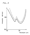
- the optical fiber has low dispersion in a wide wavelength range from 1.3 to 1.55 ⁇ m as shown by the curves A and B in Fig. 2.
- a radius (a) of the core, a radius (b) of the first cladding, ⁇ 1 and ⁇ 2 specific refractive index difference between the core 1 and the second cladding 3
- the characteristic corresponding to the curve B is effective in a wavelength range from 1.3 to 1.55 ⁇ m.
- the line C represents dispersion characteristics of a conventional step index optical fiber.
- optical fiber having a double cladding structure as shown in Fig. 1 is used in a severe environment such as in a hydrogen atmosphere or with gamma-ray radiation, its light transmission characteristics are deteriorated.
- the optical fiber comprising the core made of GeO2-containing SiO2 when placed in the hydrogen atmosphere, hydrogen diffuses into the core and forms hydroxy groups therein. If the hydroxy groups are formed by a reaction between hydrogen and GeO2, transmission attenuation of light increases not only in a wavelength range near 1.4 ⁇ m but also in a wavelength range longer than 1.5 ⁇ m because of tailing of IR absorption by the hydroxy groups in a 2.7 ⁇ m wavelength band.
- the hydroxy groups are formed by an irreversible reaction between hydrogen and GeO2 and never be removed. The number of hydroxy groups to be formed depends on a content of GeO2 in the core (cf. Electrical Communications Laboratories Technical Journal, Japan, Vol. 35, No. 6 (1986) 625-631).
- the optical fiber which comprises the core made of GeO2-containing SiO2 is not suitable to be used under severe conditions and has low long term reliability.
- An object of the present invention is to provide an SiO2 based glass optical fiber which has low attenuation of light transmission and small chromatic dispersion in a wide wavelength range and improved environmental resistance and reliability.
- an optical fiber comprising a core at least a center portion of which is made of glass essentially consisting of silica, a first cladding which is provided around the core and has a refrac tive index smaller than that of the core and a second cladding which is provided around the first cladding and has a refractive index larger than that of the first cladding and lower than that of the core.
- the core of the optical fiber according to the present invention does not contain a substantial amount of GeO2, the substantial number of the hydroxy groups are not formed by the reaction of hydrogen with GeO2 or any light absorption center is not generated by irradiation.
- Figs. 3A and 3B show refractive index profiles of two preferred embodiments of the optical fibers according to the present invention.
- the optical fiber shown in Fig. 3A comprises a core 11 made of pure silica (SiO2), a first cladding 12 made of a fluorine-added silica and a second cladding 13 made of a silica to which fluorine is added in an amount smaller than that added to the first cladding. Since no part of the optical fiber contains GeO2, no hydroxy group is formed by the reaction of hydrogen with GeO2 when the optical fiber is used in the hydrogen atmosphere, and in turn no IR absorption in the 1.4 and 2.7 ⁇ m wavelength bands. As the result, increase of transmission attenuation of light in the 1.55 and 1.3 ⁇ m wavelength bands is prevented. Further, when the optical fiber of the present invention is irradiated, no absorption center is formed, whereby increase of transmission attenuation of light is suppressed.
- SiO2 pure silica
- Fig. 3B shows a refractive index profile of an optical fiber which is a modification of the optical fiber of Fig. 3A.
- the optical fiber of Fig. 3B comprises the core 11 and the cladding 12 which are made of the same glass materials as used for the core and the first cladding of the optical fiber of Fig. 3A, but the second cladding 13 ⁇ has a different refractive index profile from that of the second cladding 13 of Fig. 3A. Namely, the inner part of the second cladding 13 ⁇ has a refractive index higher than that of the outer part thereof as shown in Fig. 3B. Thereby, on one hand, environmental resistance of the optical fiber is improved and on the other hand, bending loss of the optical fiber is decreased.
- n1 > n3 > n2 are refractive indices of the core 11, the first cladding 12 and the second cladding 13,13 ⁇ , respectively.
- a radius (b) of the first cladding, ⁇ 1 and ⁇ 2 is realized.
- the following parameters are selected: ⁇ 1: 0.9 to 1.2 %, preferably 1.0 to 1.1 % ⁇ 1- ⁇ 2: 0.2 to 0.6 %, preferably 0.3 to 0.4 % R a (a/b): 0.3 to 0.7, preferably 0.5 to 0.6
- the following parameters are selected: ⁇ 1: 0.9 - 1.2 %, preferably 1.0 to 1.1 % ⁇ 1 - ⁇ 2: 0.2 to 0.6 %, preferably 0.4 to 0.5 % R a (a/b):
- the optical fiber of the present invention may be produced by inserting a core in a hollow cylindrical glass having the glass composition for the first cladding, then inserting the integrated core and the first cladding in another hollow cylindrical glass having the glass composition for the second cladding and then integrating them together followed by drawing to produce the optical fiber.
- an optical fiber comprising the core made of pure silica and the first and second claddings made of silica added by fluorine in different amounts was produced by adjusting the radius (a) to 2.4 ⁇ m, the radius (b) to 6.1 ⁇ m, ⁇ 1 to 0.97 % and ⁇ 2 to 0.31 %.
- an optical fiber having the refractive index profile of Fig. 1 and comprising the core made of GeO2-containing silica, the first cladding made of fluorine added silica and the second cladding made of pure silica was produced by adjusting the radius (a) to 2.5 ⁇ m, the radium (b) to 5.1 ⁇ m, ⁇ 1 to 1.09 % and ⁇ 2 to 0.38 %.
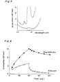
- the produced optical fibers originally had attenuation characteristics shown in Fig. 4 by the solid curve (Example) and the point and dashed curve (Comparative Example).
- the optical fiber of the present invention had attenuation of 0.247 dB/km at the wavelength of 1.55 ⁇ m, while the comparative optical fiber had attenuation of 0.310 dB/km at the wavelength of 1.55 ⁇ m.
- the less attenuation of the optical fiber of the present invention is due to the core made of pure silica, while the comparative optical fiber had large attenuation due to Rayleigh scattering loss caused by GeO2 contained in the core glass.
- the radiation resistance of the both optical fibers was examined as follows:
- Each optical fiber was irradiated by gamma-ray from 60Co at an irradiation rate of 105 R/hr for 1 hour and then increase of attenuation at the wavelength of 1.3 ⁇ m was measured.
- the results are plotted in Fig. 6. From the results, it is understood that increase of attenuation of the optical fiber of the present invention was about one third of that of the comparative optical fiber.
- increase of attenuation of the optical fiber of the present invention was about one third of that of the comparative optical fiber.
- the characteristic of the optical fiber of the present invention is recovered more quickly than the comparative optical fiber, and attenuation of the former after one hour from termination of irradiation was about one tenth of that of the comparative optical fiber.
- silica for the core of the optical fiber may contain GeO2 in such very small amount that the environmental resistance of the optical fiber is not adversely affected, for example, less than 0.2 % by weight.
- the refractive index of the core may decrease towards the first cladding. Further, the refractive index may smoothly change at an interface between the core and the first cladding or between the first cladding and the second cladding.
Applications Claiming Priority (2)
| Application Number | Priority Date | Filing Date | Title |
|---|---|---|---|
| JP62041718A JPS63208003A (ja) | 1987-02-25 | 1987-02-25 | 光フアイバ |
| JP41718/87 | 1987-02-25 |
Publications (1)
| Publication Number | Publication Date |
|---|---|
| EP0283748A1 true EP0283748A1 (de) | 1988-09-28 |
Family
ID=12616202
Family Applications (1)
| Application Number | Title | Priority Date | Filing Date |
|---|---|---|---|
| EP88102719A Withdrawn EP0283748A1 (de) | 1987-02-25 | 1988-02-24 | Optische Fiber |
Country Status (3)
| Country | Link |
|---|---|
| EP (1) | EP0283748A1 (de) |
| JP (1) | JPS63208003A (de) |
| AU (1) | AU601263B2 (de) |
Cited By (11)
| Publication number | Priority date | Publication date | Assignee | Title |
|---|---|---|---|---|
| EP0411527A1 (de) * | 1989-08-02 | 1991-02-06 | Alcatel Fibres Optiques | Verfahren zur Herstellung einer optischen Faser mit dotiertem Mantel |
| US5027079A (en) * | 1990-01-19 | 1991-06-25 | At&T Bell Laboratories | Erbium-doped fiber amplifier |
| US5361319A (en) * | 1992-02-04 | 1994-11-01 | Corning Incorporated | Dispersion compensating devices and systems |
| EP0698582A3 (de) * | 1994-08-26 | 1996-11-13 | Sumitomo Electric Industries | Verfahren zum Herstellen einer Dispertionkompensationsfaser |
| EP0762159A2 (de) * | 1995-08-31 | 1997-03-12 | Sumitomo Electric Industries, Ltd. | Dispersionskompensierende Faser und Verfahren zu ihrer Herstellung |
| FR2788180A1 (fr) * | 1999-01-04 | 2000-07-07 | Cit Alcatel | Systeme de transmission a fibre optique a multiplexage en longueur d'onde |
| EP1030198A1 (de) * | 1999-02-18 | 2000-08-23 | Alcatel | Optische Faser mit Stufenbrechungsindex und grosser Bandbreite |
| EP1235084A2 (de) * | 2001-02-27 | 2002-08-28 | The Furukawa Electric Co., Ltd. | Optische Faser mit geringer Dämpfung |
| EP1518832A1 (de) * | 2003-09-19 | 2005-03-30 | Samsung Electronics Co., Ltd. | Optische Faser und Methode zur Herstellung der entsprechenden Vorform |
| US20110091175A1 (en) * | 2007-05-04 | 2011-04-21 | Sanders Paul E | Single mode optical fiber with improved bend performance |
| US20110142404A1 (en) * | 2008-08-20 | 2011-06-16 | Futong Group Co., Ltd. | Bend Insensitive Single Mode Fiber |
Families Citing this family (3)
| Publication number | Priority date | Publication date | Assignee | Title |
|---|---|---|---|---|
| US5032001A (en) * | 1990-03-09 | 1991-07-16 | At&T Bell Laboratories | Optical fiber having enhanced bend resistance |
| EP1239312A4 (de) * | 1999-09-27 | 2005-09-21 | Sumitomo Electric Industries | Vertriebsmanagement für glasfaserkabel, deren herstellungsmethode, optische kommunikationssysteme, die glasfasertechnik und glasfaserbasiertes material nutzen |
| US7773847B2 (en) | 2005-04-28 | 2010-08-10 | Sumitomo Electric Industries, Ltd. | Multimode optical fiber |
Citations (6)
| Publication number | Priority date | Publication date | Assignee | Title |
|---|---|---|---|---|
| US4435040A (en) * | 1981-09-03 | 1984-03-06 | Bell Telephone Laboratories, Incorporated | Double-clad optical fiberguide |
| US4447127A (en) * | 1982-04-09 | 1984-05-08 | Bell Telephone Laboratories, Incorporated | Low loss single mode fiber |
| US4447125A (en) * | 1981-06-09 | 1984-05-08 | Bell Telephone Laboratories, Incorporated | Low dispension single mode fiber |
| EP0131634A1 (de) * | 1983-06-29 | 1985-01-23 | ANT Nachrichtentechnik GmbH | Monomode W-Faser |
| EP0164681A2 (de) * | 1984-06-15 | 1985-12-18 | Polaroid Corporation | Optische Monomodfiber |
| DE3500672A1 (de) * | 1985-01-11 | 1986-07-17 | Philips Patentverwaltung | Lichtleitfaser mit fluordotierung und verfahren zu deren herstellung |
Family Cites Families (2)
| Publication number | Priority date | Publication date | Assignee | Title |
|---|---|---|---|---|
| JPS5816161A (ja) * | 1981-07-22 | 1983-01-29 | 株式会社日立製作所 | 給湯空調機 |
| JPS5827213A (ja) * | 1981-08-12 | 1983-02-17 | Matsushita Electric Works Ltd | 温度補償回路 |
-
1987
- 1987-02-25 JP JP62041718A patent/JPS63208003A/ja active Pending
-
1988
- 1988-02-24 EP EP88102719A patent/EP0283748A1/de not_active Withdrawn
- 1988-02-24 AU AU12140/88A patent/AU601263B2/en not_active Ceased
Patent Citations (6)
| Publication number | Priority date | Publication date | Assignee | Title |
|---|---|---|---|---|
| US4447125A (en) * | 1981-06-09 | 1984-05-08 | Bell Telephone Laboratories, Incorporated | Low dispension single mode fiber |
| US4435040A (en) * | 1981-09-03 | 1984-03-06 | Bell Telephone Laboratories, Incorporated | Double-clad optical fiberguide |
| US4447127A (en) * | 1982-04-09 | 1984-05-08 | Bell Telephone Laboratories, Incorporated | Low loss single mode fiber |
| EP0131634A1 (de) * | 1983-06-29 | 1985-01-23 | ANT Nachrichtentechnik GmbH | Monomode W-Faser |
| EP0164681A2 (de) * | 1984-06-15 | 1985-12-18 | Polaroid Corporation | Optische Monomodfiber |
| DE3500672A1 (de) * | 1985-01-11 | 1986-07-17 | Philips Patentverwaltung | Lichtleitfaser mit fluordotierung und verfahren zu deren herstellung |
Cited By (22)
| Publication number | Priority date | Publication date | Assignee | Title |
|---|---|---|---|---|
| EP0411527A1 (de) * | 1989-08-02 | 1991-02-06 | Alcatel Fibres Optiques | Verfahren zur Herstellung einer optischen Faser mit dotiertem Mantel |
| FR2650584A1 (fr) * | 1989-08-02 | 1991-02-08 | Comp Generale Electricite | Procede de fabrication d'une fibre optique a gaine dopee |
| US5090979A (en) * | 1989-08-02 | 1992-02-25 | Compagnie Generale D'electricite | Method of manufacturing an optical fiber preform having doped cladding |
| US5027079A (en) * | 1990-01-19 | 1991-06-25 | At&T Bell Laboratories | Erbium-doped fiber amplifier |
| US5361319A (en) * | 1992-02-04 | 1994-11-01 | Corning Incorporated | Dispersion compensating devices and systems |
| EP0935146A2 (de) | 1992-02-04 | 1999-08-11 | Corning Incorporated | Dispersionkompensierende Vorrichtungen und Systeme |
| EP0698582A3 (de) * | 1994-08-26 | 1996-11-13 | Sumitomo Electric Industries | Verfahren zum Herstellen einer Dispertionkompensationsfaser |
| EP0762159A2 (de) * | 1995-08-31 | 1997-03-12 | Sumitomo Electric Industries, Ltd. | Dispersionskompensierende Faser und Verfahren zu ihrer Herstellung |
| EP0762159A3 (de) * | 1995-08-31 | 1997-07-02 | Sumitomo Electric Industries | Dispersionskompensierende Faser und Verfahren zu ihrer Herstellung |
| FR2788180A1 (fr) * | 1999-01-04 | 2000-07-07 | Cit Alcatel | Systeme de transmission a fibre optique a multiplexage en longueur d'onde |
| EP1030198A1 (de) * | 1999-02-18 | 2000-08-23 | Alcatel | Optische Faser mit Stufenbrechungsindex und grosser Bandbreite |
| FR2790106A1 (fr) * | 1999-02-18 | 2000-08-25 | Cit Alcatel | Fibre optique a saut d'indice a large bande |
| EP1235084A2 (de) * | 2001-02-27 | 2002-08-28 | The Furukawa Electric Co., Ltd. | Optische Faser mit geringer Dämpfung |
| EP1235084A3 (de) * | 2001-02-27 | 2004-09-08 | The Furukawa Electric Co., Ltd. | Optische Faser mit geringer Dämpfung |
| US6952516B2 (en) | 2001-02-27 | 2005-10-04 | The Furukawa Electric Co., Ltd. | Low attenuation optical fiber |
| EP1518832A1 (de) * | 2003-09-19 | 2005-03-30 | Samsung Electronics Co., Ltd. | Optische Faser und Methode zur Herstellung der entsprechenden Vorform |
| US20110091175A1 (en) * | 2007-05-04 | 2011-04-21 | Sanders Paul E | Single mode optical fiber with improved bend performance |
| GB2490264A (en) * | 2007-05-04 | 2012-10-24 | Weatherford Lamb | Optical waveguide |
| GB2490264B (en) * | 2007-05-04 | 2013-06-19 | Weatherford Lamb | Single mode optical fiber with improved bend performance |
| US8712202B2 (en) | 2007-05-04 | 2014-04-29 | Weatherford/Lamb, Inc. | Single mode optical fiber with improved bend performance |
| US20110142404A1 (en) * | 2008-08-20 | 2011-06-16 | Futong Group Co., Ltd. | Bend Insensitive Single Mode Fiber |
| US8750664B2 (en) * | 2008-08-20 | 2014-06-10 | Futong Group Co., Ltd. | Bend insensitive single mode fiber |
Also Published As
| Publication number | Publication date |
|---|---|
| AU1214088A (en) | 1988-09-01 |
| AU601263B2 (en) | 1990-09-06 |
| JPS63208003A (ja) | 1988-08-29 |
Similar Documents
| Publication | Publication Date | Title |
|---|---|---|
| EP0283748A1 (de) | Optische Fiber | |
| US7526177B2 (en) | Fluorine-doped optical fiber | |
| CA1124119A (en) | Single mode optical fibers | |
| EP0674193B1 (de) | Dispersionskompensierende optische Faser und optisches Übertragungssystem mit solcher optischer Faser | |
| AU529144B2 (en) | High bandwidth optical waveguide | |
| US5732178A (en) | Single-mode optical fiber | |
| AU719606B2 (en) | Optical fiber grating | |
| EP0310293A2 (de) | Beschichtete optische Wellenleiterfaser | |
| US4025156A (en) | Graded-index fiber for multimode optical communication | |
| EP0294037A1 (de) | Faseroptisches Dämpfungsglied | |
| CN1198219A (zh) | 色散补偿单模波导 | |
| CA2655009A1 (en) | Optical system and method having low loss and non-linear effects | |
| US20040213531A1 (en) | Optical fiber, optical fiber tape, optical cable and optical connector with optical fiber | |
| EP0540042B1 (de) | Glasfaser für hohe Eingangsleistung und Herstellungsverfahren dafür | |
| CA1268972A (en) | Long wavelength optical fiber communication and sensing systems | |
| US4525027A (en) | Single mode optical fibers | |
| Cohen et al. | Dispersion and bandwidth spectra in single-mode fibers | |
| Kitayama et al. | Design considerations for the structural optimization of a single-mode fiber | |
| EP0198118B1 (de) | Einwelliger Lichtwellenleiter aus Quarzglas und Verfahren zu dessen Herstellung | |
| US20050152654A1 (en) | Reduced four-wave mixing optical fiber for wavelength-division multiplexing | |
| EP0234455A3 (de) | Berylliumfluorid enthaltende optische Fasern | |
| Cohen et al. | Transmission Studies of a Long Single‐Mode Fiber—Measurements and Considerations for Bandwidth Optimization | |
| JPH01224706A (ja) | 光ファイバ | |
| JP2724828B2 (ja) | 光ファイバ | |
| JPS63208005A (ja) | 光フアイバ |
Legal Events
| Date | Code | Title | Description |
|---|---|---|---|
| PUAI | Public reference made under article 153(3) epc to a published international application that has entered the european phase |
Free format text: ORIGINAL CODE: 0009012 |
|
| AK | Designated contracting states |
Kind code of ref document: A1 Designated state(s): DE FR GB IT |
|
| 17P | Request for examination filed |
Effective date: 19890125 |
|
| 17Q | First examination report despatched |
Effective date: 19910206 |
|
| STAA | Information on the status of an ep patent application or granted ep patent |
Free format text: STATUS: THE APPLICATION IS DEEMED TO BE WITHDRAWN |
|
| 18D | Application deemed to be withdrawn |
Effective date: 19910817 |