EP0283229A2 - Verfahren zur Herstellung eines rohrförmigen Gegenstandes - Google Patents
Verfahren zur Herstellung eines rohrförmigen Gegenstandes Download PDFInfo
- Publication number
- EP0283229A2 EP0283229A2 EP88302201A EP88302201A EP0283229A2 EP 0283229 A2 EP0283229 A2 EP 0283229A2 EP 88302201 A EP88302201 A EP 88302201A EP 88302201 A EP88302201 A EP 88302201A EP 0283229 A2 EP0283229 A2 EP 0283229A2
- Authority
- EP
- European Patent Office
- Prior art keywords
- webs
- mandrel
- side edges
- tubular member
- web
- Prior art date
- Legal status (The legal status is an assumption and is not a legal conclusion. Google has not performed a legal analysis and makes no representation as to the accuracy of the status listed.)
- Ceased
Links
Images


Classifications
-
- B—PERFORMING OPERATIONS; TRANSPORTING
- B31—MAKING ARTICLES OF PAPER, CARDBOARD OR MATERIAL WORKED IN A MANNER ANALOGOUS TO PAPER; WORKING PAPER, CARDBOARD OR MATERIAL WORKED IN A MANNER ANALOGOUS TO PAPER
- B31F—MECHANICAL WORKING OR DEFORMATION OF PAPER, CARDBOARD OR MATERIAL WORKED IN A MANNER ANALOGOUS TO PAPER
- B31F7/00—Processes not otherwise provided for
- B31F7/004—Making tubes
-
- B—PERFORMING OPERATIONS; TRANSPORTING
- B29—WORKING OF PLASTICS; WORKING OF SUBSTANCES IN A PLASTIC STATE IN GENERAL
- B29C—SHAPING OR JOINING OF PLASTICS; SHAPING OF MATERIAL IN A PLASTIC STATE, NOT OTHERWISE PROVIDED FOR; AFTER-TREATMENT OF THE SHAPED PRODUCTS, e.g. REPAIRING
- B29C31/00—Handling, e.g. feeding of the material to be shaped, storage of plastics material before moulding; Automation, i.e. automated handling lines in plastics processing plants, e.g. using manipulators or robots
- B29C31/002—Handling tubes, e.g. transferring between shaping stations, loading on mandrels
-
- B—PERFORMING OPERATIONS; TRANSPORTING
- B31—MAKING ARTICLES OF PAPER, CARDBOARD OR MATERIAL WORKED IN A MANNER ANALOGOUS TO PAPER; WORKING PAPER, CARDBOARD OR MATERIAL WORKED IN A MANNER ANALOGOUS TO PAPER
- B31F—MECHANICAL WORKING OR DEFORMATION OF PAPER, CARDBOARD OR MATERIAL WORKED IN A MANNER ANALOGOUS TO PAPER
- B31F1/00—Mechanical deformation without removing material, e.g. in combination with laminating
- B31F1/0003—Shaping by bending, folding, twisting, straightening, flattening or rim-rolling; Shaping by bending, folding or rim-rolling combined with joining; Apparatus therefor
- B31F1/0045—Bending or folding combined with joining
- B31F1/0048—Bending plates, sheets or webs at right angles to the axis of the article being formed and joining the edges
- B31F1/0061—Bending plates, sheets or webs at right angles to the axis of the article being formed and joining the edges for making articles of indefinite length
- B31F1/0064—Bending plates, sheets or webs at right angles to the axis of the article being formed and joining the edges for making articles of indefinite length using internal forming surfaces, on, e.g. mandrels
-
- B—PERFORMING OPERATIONS; TRANSPORTING
- B31—MAKING ARTICLES OF PAPER, CARDBOARD OR MATERIAL WORKED IN A MANNER ANALOGOUS TO PAPER; WORKING PAPER, CARDBOARD OR MATERIAL WORKED IN A MANNER ANALOGOUS TO PAPER
- B31F—MECHANICAL WORKING OR DEFORMATION OF PAPER, CARDBOARD OR MATERIAL WORKED IN A MANNER ANALOGOUS TO PAPER
- B31F1/00—Mechanical deformation without removing material, e.g. in combination with laminating
- B31F1/0003—Shaping by bending, folding, twisting, straightening, flattening or rim-rolling; Shaping by bending, folding or rim-rolling combined with joining; Apparatus therefor
- B31F1/0045—Bending or folding combined with joining
- B31F1/0048—Bending plates, sheets or webs at right angles to the axis of the article being formed and joining the edges
- B31F1/007—Bending plates, sheets or webs at right angles to the axis of the article being formed and joining the edges for making articles with multilayered walls
-
- Y—GENERAL TAGGING OF NEW TECHNOLOGICAL DEVELOPMENTS; GENERAL TAGGING OF CROSS-SECTIONAL TECHNOLOGIES SPANNING OVER SEVERAL SECTIONS OF THE IPC; TECHNICAL SUBJECTS COVERED BY FORMER USPC CROSS-REFERENCE ART COLLECTIONS [XRACs] AND DIGESTS
- Y10—TECHNICAL SUBJECTS COVERED BY FORMER USPC
- Y10T—TECHNICAL SUBJECTS COVERED BY FORMER US CLASSIFICATION
- Y10T156/00—Adhesive bonding and miscellaneous chemical manufacture
- Y10T156/10—Methods of surface bonding and/or assembly therefor
- Y10T156/1002—Methods of surface bonding and/or assembly therefor with permanent bending or reshaping or surface deformation of self sustaining lamina
- Y10T156/1007—Running or continuous length work
- Y10T156/1008—Longitudinal bending
- Y10T156/1013—Longitudinal bending and edge-joining of one piece blank to form tube
Definitions
- the present invention relates to an apparatus for continuously manufacturing a tubular member by overlapping and bonding flexible webs or strips as a plurality of layers.
- a plurality of flexible webs or strips are overlapped in transversely shifted positions so that their side edges are shaped like a staircase.
- the overlapped webs are first bonded at narrow areas thereof positioned intermediate between their opposite side edges, and then progressively bent around a mandrel into a tubular form.
- the widths of the bonded areas of the overlapped webs are progressively increased toward the opposite side edges until the opposite side edges are joined.
- the opposite edges of the positionally shifted webs are held in abutment against and coupled to each other thereby to continuously form a complete tubular member, which is withdrawn along the mandrel and then cut off to a suitable length.
- the bonded areas of the webs are prevented from being wrinkled.
- the adhesive used is a water-soluble adhesive
- the bonded strips are allowed to be positionally displaced for a relatively long period of time after they have been bonded, because the adhesive is of a liquid state. Therefore, no special care is required during the bonding process at the time of progressively increasing the bonded areas.
- water-soluble adhesive is problematic for the following reasons: A long period of time is required for the water-soluble adhesive to be dried.
- a water-resistant layer must be added as an outermost or innermost layer. With the water-resistant layer added, the adhesive cannot easily be dried. Therefore, if a tubular member for use as a liquid container is to be manufactured, then it is preferable to employ a hot-melt adhesive which does not need to be dried.
- the hot-melt adhesive When the hot-melt adhesive is applied to form a tubular member from webs, the webs are firmly secured to each other at the same time that they are bonded by the hot-melt adhesive. Unless, therefore, the webs are uniformly bonded even at localized areas thereof, the webs are subjected to wrinkles, giving rise to non-bonded areas which tend to reduce the pressure resistance of the produced tubular member. Thus, with the use of the hot-melt adhesive, any tubular member of high quality cannot be formed simply by progressively increasing the bonded areas.
- the hot-melt adhesive is advantageous over the water-soluble adhesive since the speed at which the tubular member is formed can be increased with the hot-melt adhesive being relied upon.
- the joined opposite side edges of the webs are held in abutment against each other as described above. This is advantageous in that even if the side edges of the webs are positionally displaced slightly when forming the tubular member, they can form joined areas.
- the side edges of the webs X, Y, Z should be positioned such that the outer side edge x2 abut against the inner side edge y1 and the outer side edge y2 abut against the inner side edge z1. Otherwise, gaps would be created between the outer side edge x2 and the inner side edge y1 and between the outer side edge y2 and the inner side edge z1, thereby reducing the pressure resistance.
- an innermost layer U is required to give the container barrel water resistance and sealing capability.
- the innermost layer U comprises a water-resistant layer as a gas barrier.
- the layer U and the webs X, Y, Z are wound around a mandrel to form a tubular member, and the opposite side edges of the layer U are joined to each other for sealing capability. More specifically, as shown in FIG. 26, the innermost layer U is formed as a tubular body, and its opposite side edges u1, u2 mate against each other, are bonded to each other, then folded to one side, and finally bonded to an outer surface of the tubular member.
- the innermost layer U Prior to the formation of the tubular member from the outer webs X, Y, Z, the innermost layer U is bent to its form along the mandrel so that the joined side edges u1, u2 will be disposed inside of the tubular member.
- the webs U, X, Y, Z used to form the tubular member are in the form of elongate strips, which are continuously supplied along the mandrel. It is efficient to form the tubular member from the webs X, Y, Z after the innermost layer has been formed from the web U. Therefore, an apparatus is required to form the innermost layer.
- Another object of the present invention is to provide an apparatus for continuously manufacturing a tubular member by overlapping and bonding flexible webs or strips as a plurality of layers with a hot-melt adhesive.
- Still another object of the present invention is to provide an apparatus for continuously manufacturing a tubular member for use as a beverage container by overlapping and bonding a plurality of layers in the form of paper webs and another flexible water-resistant web.
- a further object of the present invention is to provide an apparatus for continuously manufacturing a tubular member for use as a highly pressure-resistant container capable of containing a liquid, such as a sparkling beverage, which will exert a high internal pressure when filled in the container.
- an apparatus for manufacturing a tubular member by continuously supplying a plurality of elongate flexible webs while positionally displacing the webs in overlapping relation with side edges thereof arranged in a staircase configuration, progressively bending the webs along a mandrel, bonding the webs with adhesive layers interposed therebetween to form a tubular member, and joining the displaced side edges to complete the tubular member
- said apparatus comprising: a device for continuously supplying the webs in mutually spaced-apart relation while longitudinally tensioning the webs; a plurality of resilient support plate members disposed respectively for the webs and arranged to lie along the lower surfaces of the webs transversely thereof; a mandrel; devices supporting opposite ends of the support plate members for moving said opposite ends vertically and toward and away from each other, said devices being capable of moving said opposite ends of the support plate members toward each other to curve the support members along an outer peripheral surface of said mandrel; and a positioning device having
- the opposite ends of the support plate members are moved vertical and toward and away from each other by the respective supporting devices to move the guide members engaging the opposite side edges of the webs vertically and transversely of the webs without changing the curved shapes of the intermediate portions of the support plate members along the outer circumference of the mandrel.
- the webs are supported on the curved intermediate portions of the respective support plate members, and the side edges of the webs are positionally displaced transversely into a staircase shape and vertically overlapped.
- the side edges of the webs are positioned such that when the webs are bent along the mandrel into the tubular member, outer side edges of overlapping joined portions of webs are held in abutment against inner side edges of the joined portions of upper webs.
- an apparatus for manufacturing a tubular member by continuously supplying a plurality of elongate flexible webs while positionally displacing the webs in overlapping relation with side edges thereof arranged in a staircase configuration, progressively bending the webs along a mandrel, bonding the webs with adhesive layers interposed therebetween to form a tubular member, and joining the displaced side edges to complete the tubular member
- said apparatus comprising: a device for supplying the elongate webs in mutually spaced-apart relation while longitudinally tensioning the webs, each of the webs having a hot-melt adhesive on at least one surface thereof; a mandrel disposed to lie at an intermediate position between opposite side edges of an innermost one of the webs and extend along the webs; a device having a plurality of rollers each having a pressing surface complementary to a portion of an outer circumferential surface of the mandrel for pressing the webs against said mandrel, said rollers being positionally displaced
- the hot-melt adhesive coated on each of the webs is melted by the heating device until the webs are shaped to tubular form.
- the webs are longitudinally tensioned to keep them spaced apart from each other immediately before the webs are bonded, and forces tending to press the webs against the mandrel are applied by the rollers and continuously impressed linearly in circumferential directions of the mandrel to shape the web into a tubular body.
- the region in which each of the webs is bonded is progressively increased transversely to the full width of the webs, or from a certain circumferential position on the mandrel toward the entire circumferential surface in the longitudinal direction of the webs.
- non-bonded regions of the webs are progressively reduced transversely of the webs, or from the certain circumferential position on the mandrel toward the entire circumferential surface in the longitudinal direction of the webs, the non-bonded regions being free from the bonded regions.
- any wrinkles of the webs are eliminated or released from the side edges thereof while the webs are being bonded.
- the webs can be bonded in this manner by arranging the rollers each having a pressing surface complementary to a portion of an outer circumferential surface of the mandrel for pressing the webs against said mandrel, such that the rollers are positionally displaced longitudinally of the mandrel and partly overlapped circumferentially of the mandrel sucessively from one of said rollers around the mandrel when viewed in an axial direction of the mandrel, and by pressing the rollers against the mandrel with the webs therebetween.
- the tubular member to be formed is of a circular or elliptical cross section, and hence the mandrel has a circular or elliptical cross section
- the pressing surface of each of the rollers is of an arcuate shape along the outer circumferential surface of the mandrel, and the axis of rotation of each roller is normal to the axis of the mandre.
- the rollers press the webs against the mandrel at the intermediate position on the arcuate pressing surfaces of the rollers.
- an apparatus for manufacturing a tubular member by continuously supplying a plurality of elongate flexible webs while positionally displacing the webs in overlapping relation with side edges thereof arranged in a staircase configuration, progressively bending the webs along a mandrel, bonding the webs with adhesive layers interposed therebetween to form a tubular member, and joining the displaced side edges to complete the tubular member
- said apparatus comprising: a device for continuously supplying an elongate web having a thermally fusible layer on a surface thereof facing the mandrel, along an innermost one of the flexible webs, while longitudinally tensioning the web; a mandrel disposed to lie at an intermediate position between opposite side edges of the web and having an outer circumferential length shorter than the distance between the opposite side edges of the web; a shaping/guiding device having a pair of semicylindrical shaping/guiding members for bending the web along said mandrel into a tubular body, said shaping/guiding members being
- the web is continuously supplied along the mandrel by the supplying device so as to pass through the shaping/guiding members which bend the web along the mandrel into a tubular body.
- the opposite side edges of the web project between the upper edges of the shaping/guiding members and are held in mating relation to each other.
- the mating side edges are then pressed and heated by the fusing device to fuse the thermally fusible layers on the side edges to join them.
- a hot-melt adhesive is coated on one surface of the joined side edges by the adhesive coating device, after which the coated surface is pressed and bonded to the outer surface of the tubular body by the pressing device, for thereby completing the tubular body.
- an apparatus for manufacturing a tubular member by continuously supplying a plurality of elongate flexible webs while positionally displacing the webs in overlapping relation with side edges thereof arranged in a staircase configuration, progressively bending the webs along a mandrel, bonding the webs with a hot-melt adhesive interposed therebetween to form a tubular member, and joining the displaced side edges to complete the tubular member, said apparatus comprising: a cooling mandrel for guiding the completed tubular member fitted thereover; a withdrawing device for withdrawing the tubular member along said cooling mandrel; and a cooling body disposed in a position in which the joined portion of the tubular member passes, for abutting against the joined portion of the tubular member.
- the tubular member formed from the webs with their opposite side edges joined is fitted over and cooled by the cooling mandrel, and the joined portion or seam of the tubular member is cooled by contact with the cooling body. Therefore, the bonding process using the hot-melt adhesive is finished in a short period of time.
- the adhesive for bonding the webs which constitute a major portion of the tubular member should preferably be a hot-melt adhesive, as described above.
- the hot-melt adhesive may be of a known nature,nd may be polyethylene, ethylene and ethylene copolymer, ethylene vinyl acetate copolymer, ethylene methyl methacrylate copolymer, ethylene ethyl acrylate copolymer, ethylene methyl acrylate copolymer, ethylene methyl acrylate maleic anhydride copolymer, ethylene acrylic acid copolymer, ethylene methacrylic acid copolymer, ionomer resin, polyamide resin, polyester resin, nylon resin, polypropylene resin, vinyl acetate copolymer resin, polymethyl methacrylate resin, or their mixture.
- This adhesive is applied to at least one surface of the webs.
- the intermediate webs may be coated with the adhesive on their opposite surfaces.
- the hot-melt adhesive may be coated on the webs in advance and reheated into a melted condition immediately before the webs are shaped into the tubular member. Alternatively, when forming the tubular member, the melted hot-melt adhesive may be applied to the webs. The hot-melt adhesive should be kept in the melted condition with heat until the webs are shaped into the tubular member.
- the webs each with the adhesive layer are positionally displaced so that their side edges are in a staircase configuration, and overlapped in mutually spaced-apart relation.
- the webs are continuously supplied while being longitudinally tensioned. By thus continuously supplying the webs under longitudinal tension, the webs are maintained in mutually spaced-apart relation immediately before they are shaped into the tubular member.
- the mandrel having an outer profile for defining the configuration of a tubular member is disposed at an intermediate position between the opposite side edges of the webs thus continuously supplied, and the webs are progressively bent along the outer circumference of the mandrel into a tubular form. It is important that the side edges of the webs are positioned such that the side edges are overlapped, and that overlapping outer side edges of webs are held in abutment against inner side edges of upper webs.
- the webs constituting a major portion of the tubualr member are made of a flexible material such as paper, plastic, metal foil, or their combination.
- the webs are continuous elongate sheets, and the formed tubular body is thereafter cut off to a suitable length.
- the web serving as an innermost layer of the tubular member is a sheet of paper, plastic, metal foil, or the like.
- This web has a thermally fusible synthetic resin layer on at least one surface thereof in order to allow the opposite side edges to be fused and joined.
- the web is to serve as a water-resistant innermost layer, it is preferable to employ a web of paper coated with a thermally fusible synthetic resin film.
- the web is a continuous elongate sheet, and the formed tubualr body is thereafter cut off to a suitable length together with the tubular body formed from the webs that constitute the major portion of the tubular member.
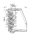
- FIGS. 1 and 2 schematically illustrate an apparatus for manufacturing a tubular member in accordance with the present invention.
- the apparatus includes a feeding device A for continuously feeding a web U having a water-resistant gas barrier surface and a plurality of paper webs X, Y, Z, a preheating device B for heating the webs X, Y, Z so that they are uniformly dried, a first positioning device C for positionally shifting or displacing the webs in overlapping relation until side edges of the webs are arranged in a staircase configuration, an adhesive applicator device D for coating a hot-melt adhesive on mutually confronting surfaces of the webs U, X, Y, Z, a heating device E having a heating means for keeping the coated adhesive in a melted condition, a second positioning device F for accurately positioning the side edges of the webs again, a first forming device G for bending the web U along a mandrel to form an innermost layer of a tubular member, a second forming device H for bending the webs X, Y, Z along a mandrel to form the tubular member, a withdrawing device
- the webs U, X, Y, Z are tensioned in their longitudinal direction by the withdrawing device I until they reach the first and second forming devices G, H.
- the feeding device A, the preheating device B, the first positioning device C, and the cutting device J are of a conventional nature.
- the second positioning device F, the first forming device G, the second forming device H, and the withdrawing device I will hereinafter be described in detail.
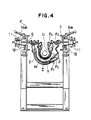
- FIGS. 3 and 4 illustrate the second positioning device F.
- the positioning device F has four positioning means F1, F2, F3, F4 of identical structure for positioning the four webs U, X, Y, Z, respectively.
- the positioning means F2 will be described with reference to FIGS. 5 through 8.
- FIG. 5 shows the positioning means F2 in plan.
- the positioning means F2 comprises a support plate member 3 in the form of a steel sheet with its opposite ends supported by bases 1, 2 disposed parallel to the direction in which the web Y is supplied, a pair of guide members 4, 5 mounted on an upper surface of the support plate member 3 and extending therealong for engaging side edges of the web Y, and a pair of support rods 6, 7 supporting the opposite ends of the support plate member 3.
- the support rods 6, 7 are movable vertically with respect to the bases 1, 2, respectively, and are also movable toward and away from each other.
- the support rods 6, 7 can be moved by identical moving means, respectively, one of which will be described below by way of example.
- the support rod 6 is inserted through a guide sleeve 10 fitted in a base block 9 vertically movably mounted on a bracket 8 attached to the base 1.
- a nut 11 is threaded over an externally threaded portion of the support rod 6 outwardly of the guide sleeve 10 for adjusting axial displacement of the support rod 6.
- the support rod 6 is fixed against axial displacement by a lock nut 12 threaded over the support rod 6 outwardly of the nut 11 and a clamping rod 14 which are threaded across a slit 13a (see FIGS.
- the base block 9 is vertically movable while being guided by a clamping rod 16 and a guide pin 17 which extend through a groove 15 vertically defined in the bracket 8, as shown in FIGS. 6 and 7.
- a vertically movable rod 18 which is rotatable about its own axis and supported on the lower end of the bracket 8 has a tip end threaded in the base block 9.
- the vertically movable rod 18 is rotated by a handle 18a to lift or lower the base block 9.
- the base block 9 is fixed against vertical movement by turning the clamping rod 16 with a handle 16a.
- the support plate member 3 has its opposite ends supported on the respective support rods 6, 7 by attachment members 19, 20, respectively, and includes near its opposite ends bent portions 21, 22 extending along the direction in which the web Y is supplied, for allowing an intermediate portion of the support plate member 3 to be easily curved.
- the guide members 4, 5 are disposed along the opposite ends of the support plate member 3 and have respective grooves 23, 24 defined in confronting ends thereof for receiving the side edges of the web Y. As illustrated in FIGS. 5, 6, and 8, the distance between the guide members 4, 5 can be adjusted by moving these members 4, 5 toward or away from each other while loosening bolts 27, 28 inserted through respective slots 25, 26 defined in the support plate member 3.
- the support rod 6 is moved toward the support rod 7 and also moved upwardly from the pre-adjustment position indicated by the imaginary lines to the solid-line position.
- the support rod 7 is moved away from the support rod 6 and also moved downwardly. Therefore, the guide members 4, 5 are turned clockwise (FIG. 9) without changing the curved shape of the support plate member 3 around a mandrel M.
- the support rod 7 is moved toward the support rod 6 and also moved upwardly from the pre-adjustment position indicated by the imaginary lines to the solid-line position.
- the support rod 6 is moved away from the support rod 7 and also moved downwardly. Therefore, the guide members 4, 5 are turned counterclockwise (FIG. 10) without changing the curved shape of the support plate member 3 around the mandrel M.
- the positioning means F1, F2, F3, F4 are adjusted in this manner as shown in FIG. 4 to position the web U and positionally shift or displace the webs X, Y, Z so that their side edges are vertically overlapped in a staircase configuration.
- the webs are also bent along the mandrel M into a tubular member.
- the web U serves as an innermost layer shaped as a tubular body
- the webs X, Y, Z serve as an outer tubular body.
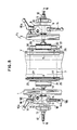
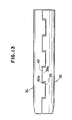
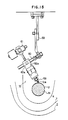
- the first forming device G is constructed as shown in FIGS. 11 to 13.
- the web U or the inner layer supplied to the first forming device G is longitudinally tensioned by the withdrawing device I until it reaches the first forming device G.
- the web U which is made of paper has one entire surface coated with a water-resistant synthetic resin film as a thermally fusible gas barrier.
- the mandrel M extends in the longitudinal direction in which the web U is continuously supplied, and is disposed intermediate between the opposite side edges of the web U in confronting relation to the thermally fusible film.
- the web U is shaped into a tubular form by a shaping/guiding device 30.
- the opposite side edges of the web U which are brought into abutting relation to each other by the shaping/guiding device 30 are joined to each other by a fusing device 31.
- the opposite side edges of the web U which are thus joined to each other by the fusing device 31 are coated with a hot-melt adhesive by an adhesive coating device 32.
- the opposite side edges of the web U are pressed and bonded by a pressing device 33 while the coated surfaces are being directed inwardly and the web U is being bent into a tubular form.
- the mandrel M has a circular cross-sectional shape and its outer circumferential length is shorter than the width between the opposite side edges of the web U.
- the shaping/guiding device 30 has a pair of semicylindrical shaping/guiding members 34, 35 and an opening/closing means 36 for enabling the shaping/guiding members 34, 35 to embrace the mandrel M on its diametrically opposite sides.
- the opening/closing means 36 is supported on a pair of laterally spaced support members 36a suspended from a frame.
- the shaping/guiding members 34, 35 has respective upper edges 37, 38 facing each other and respective lower edges 39, 40 facing each other.
- the upper edges 37, 38 are spaced from each other by a gap between which the opposite side edges Ua of the web U as it is shaped along the mandrel M project upwardly.
- the lower edges 39, 40 of the shaping/guiding members 34, 35 are in the shape of intermeshing teeth and grooves 39a, 40a for preventing the web U from entering between the lower edges 39, 40 when the web U is supplied between the shaping/guiding members 34, 35 and the mandrel M.
- the web U is guided to run along the mandrel M by guide edges 41 of the shaping/guiding members 34, 35.
- the opening/closing means 36 includes a pair of parallel guide rods 42, 43 mounted on the support members 36a and a pair of cylinders 46, 47 mounted on the support members 36a for moving support members 44, 45 of the shaping/guiding members 34, 35 toward and away from each other on and along the guide rods 42, 43.
- the fusing device 31 has a pair of heaters 49, 50 disposed in facing relation to the position where the opposite side edges Ua of the web U which are mated by the shaping/forming device 30 pass, and a means 51 for opening and closing the heaters 49, 50.
- the means 51 has a pair of L-shaped support members 52, 53 including confronting vertical portions.
- the heaters 49, 50 are mounted on lower ends, respectively, of the vertical portions of the support members 52, 53.
- the L-shaped support members 52, 53 have bent portions pivotally coupled to a common shaft 54 and horizontal portions 52a, 53a connected to piston rods 55a, 56a, respectively, of a pair of cylinders 55, 56.
- the heaters 49, 50 can be moved toward and away from each other (i.e., closed and opened) by the cylinders 55, 56.
- the cylinders 55, 56 have rear ends swingably mounted on a support member 57 by which the shaft 54 is suspended from the frame.
- the horizontal portion 52a of the support member 52 is longer than the horizontal portion 53a of the support member 53 so that the heater 50 will be closed with respect to the heater 49, the closed position of which is used as a reference.
- the adhesive coating device 32 comprises an ejector nozzle 58 for applying a hot-melt adhesive to one outer side of the opposite side edges Ua of the web U which are fused by the fusing device 31.
- the nozzle 58 has a base portion 58a positionally adjustably attached by a bolt 60a to a guide rod 60 coupled to a support member 59 suspended from the frame.
- the hot-melt adhesive is supplied through a pipe (not shown) which is associated with a regulator valve 61.
- the pressing device 33 comprises a pressing means 62 vertically movable into and out of the position where the opposite side edges Ua of the web U coated with the adhesive by the adhesive coating device 32 pass, and a means 63 for vertically moving the pressing means 62.
- the pressing means 62 has a bottom surface curved along a portion of the outer circumferential surface of the mandrel M, and includes a pipe extending over its entire length for promoting the solidification of the adhesive.
- a coolant is supplied to the pipe and flows therethrough via tubes 64, 65 coupled to the pipe.
- the means 63 for vertically moving the pressing means 62 has a link 66 swingably coupled at one end to a longitudinally central portion of the pressing means 62 and at the other end to a support member 67 suspended from the frame.
- the link 66 has an intermediate portion connected to a piston rod 69 of a cylinder 63 that has a rear end pivotally coupled to a support member 70 suspended from the frame. Since the pressing means 62 is swingably supported on the frame, no problem arises even when the opposite side edges of the bent web U have wrinkles or surface irregularities.
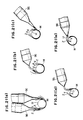
- the first forming device G will operate as follows:
- the shaping/guiding members 34, 35 of the shaping/guiding device 30 When the shaping/guiding members 34, 35 of the shaping/guiding device 30 are brought into a closed position while embracing the web U by means of the opneing/closing means 36, as shown in FIG. 11, the web U is guided by the guide edges 41 of the shaping/guiding members 34, 35 into a shape complementary to and along the mandrel M. At the same time, as shown in FIG. 12, the opposite side edges of the web U are inserted into the gap between the upper edges 37, 38 of the shaping/guiding members 34, 35 and mated together in abutment while they are projecting upwardly.
- one side of the joined side edges Ua is coated with an adhesive by the adhesive coating device 32.
- the joined side edges Ua are bent by the pressing means 62 lowered by the means 63 so that the adhesive-coated side is directed downwardly toward the mandrel M, until the joined side edges Ua are bonded to the outer surface of the tubular body.
- the webs X, Y, Z are bent along the mandrel M by the second forming device H to form a tubular body which is disposed around the tubular body formed from the web U.
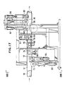
- the second forming device H is illustrated in FIGS. 17 and 18.
- the second forming device H has the mandrel M which serves to guide the tubular body formed from the web U and positioned inwardly of the webs X, Y, Z (not shown in FIGS. 17 and 18) that are continuously fed along.
- the mandrel M extends longitudinally of the webs X, Y, Z to the withdrawing device I and the cutting device J.
- rollers 71 through 82 for bending the webs X, Y, Z along the outer peripheral surface of the mandrel M into the tubular body, the rollers 71 through 82 being positionally displaced in the direction in which the webs X, Y, Z advance.
- Each of the rollers 71 through 82 has an arcuate concave surface complementary to a circumferential portion of the outer surface of the mandrel M, and has its axis of rotation normal to the axis of the mandrel M.
- the rollers 71 through 82 are arranged as follows:
- the roller 71 which first presses the webs X, Y, Z against the mandrel M is positioned at an intermediate portion between the opposite side edges of the web X.
- the rollers 72, 73 located downstream of the roller 71 in the direction of travel of the webs X, Y, Z are angularly displaced from the roller 71 in opposite circumferential directions of the mandrel M such that the arcuate pressing surfaces of the rollers 72, 73 overlap the arcuate pressing surface of the roller 71 in the longitudinal direction of the mandrel M.
- the rollers 74, 75 disposed donwstream of the rollers 72, 73 are also angularly shifted such that the arcuate pressing surfaces of the rollers 74, 72 overlap each other in the longitudinal direction of the mandrel M whereas the arcuate pressing surfaces of the rollers 75, 73 overlap each other in the longitudinal direction of the mandrel M.
- the rollers 76, 77 disposed downstream of the rollers 74, 75 are also angularly shifted such that the arcuate pressing surfaces of the rollers 76, 74 overlap each other in the longitudinal direction of the mandrel M whereas the arcuate pressing surfaces of the rollers 77, 75 overlap each other in the longitudinal direction of the mandrel M.
- the other rollers 78 through 82 are similarly positioned. Therefore, the arcuate pressing surfaces of the rollers 71 through 82 cover the entire circumferential surface the mandrel M in overlapping relation.
- the rollers 71 through 82 are connected to respective cylinders 83 through 94 which serve to press the centers of the arcuate pressing surfaces of the rollers toward the mandrel M.
- the tubular body formed by the second forming device H is supported and guided by a support roller 95 (FIG. 17).
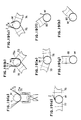
- the rollers 71 through 82 can apply forces tending to press the webs X, Y, Z against the mandrel M, the forces being applied continuously in linear directions from the roller 71 circumferentially of the mandrel M.
- the webs X, Y, Z are pressed against the mandrel M by the roller 71 and bonded together in overlapping relation by intervening hot-melt adhesive layers.
- the pressing force applied is maximum at a central area 71a of the arcuate pressing surface of the roller 71, and becomes progressively smaller toward the side edges of the arcuate pressing surface of the roller 71. Therefore, the webs X, Y, Z are firmly bonded together at the central area 71a, and bonded progressively less sufficiently toward the side edges of the arcuate pressing surface of the roller 71.
- the pressing forces are linearly shifted toward the opposite side edges of the webs X, Y, Z by the rollers 74 through 79 to bend the webs X, Y, Z into a shape complementary to the outer circumferential shape of the mandrel M.
- each of the webs X, Y, Z is bent by the roller 78 so that it abuts against the mandrel M earlier than the other side edge thereof.
- the other side edges of the webs X, Y, Z are bonded in overlapping relation to form a completely bonded tubular member.
- FIG. 20 shows a heating device associated with the second forming device H.
- the heating device has nozzles 96 housing heaters therein for ejecting heated air into the spaces between the webs X, Y, Z to keep the hot-melt adhesive layers coated on the webs X, Y, Z in a melted condition.
- the plural nozzles 96 are provided for keeping the hot-melt adhesive reliably melted immediately before the webs X, Y, Z bent by the second forming device H are bonded by the hot-melt adhesive.
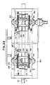
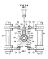
- the withdrawing device I is illustrated in detail in FIGS. 22 through 25.
- the tubular member, designated at T, which is formed coaxially with the mandrel M is withdrawn from the second forming device H by the withdrawing device I while it is being fitted over and guided by a cooling mandrel 97 extending through the withdrawing device I. Cooling water 98 is supplied so as to circulate in the cooling mandrel 97 throughout its entire length, as shown in FIGS. 24 and 25.
- the tubular member T has a joined portion of seam Ta positioned along an upper edge of the cooling mandrel 97.
- the withdrawing device I has a pair of endless feeding/gripping means 99 disposed in confronting relation to each other along the cooling mandrel 97 for gripping the tubular member T between the feeding/gripping means 99 and the cooling mandrel 97 and for withdrawing the tubular member T.
- Each of the feeding/gripping means 99 comprises a driver shaft 101 and a driven shaft 102 which are vertically disposed at front and rear positions on support frames 100 arranged along the cooling mandrel 97.
- Each of the shafts 101, 102 supports first and second gears 103, 104 on its upper and lower portions, and endless chains 105, 106 are trained around the first gears 103 and the second gears 104.
- a number of gripping members 107 are vertically disposed on and between the chains 105, 106 for engaging the surface of the tubular member T fitted over the cooling mandrel 97.
- paired gripping members 107 have respective gripping surfaces 108 curved for gripping confronting peripheral surfaces of the tubular member T fitted over the cooling mandrel 97, the paired gripping members 107 being spaced from each other at positions above and below the tubular member T.
- a cooling body 109 is disposed in a gap or space defined between the gripping members 109 of the gripping means 99, the cooling body 109 extending along the upper edge of the cooling mandrel 97.
- the cooling body 109 is supplied with circulating cooling water 110 as shown in FIG. 24.
- the cooling body 109 can be lowered by a pair of links 111 so as to be seated on the tubular member T fitted over the cooling mandrel 97, in an area around the joined portion Ta of the tubular member T.
- the tubular member T formed from the webs X, Y, Z with their side edges joined by the second forming device H is withdrawn along the cooling mandrel 97 while being gripped by the gripping means 99 in the withdrawing device I.
- the tubular member T is cooled from its inner surface by the cooling mandrel 97 over which the tubular member T is fitted.
- the joined portion Ta is cooled from its outer surface by the cooling body 109 to complete the solidification of the hot-melt adhesive in the joined portion Ta.
Landscapes
- Engineering & Computer Science (AREA)
- Mechanical Engineering (AREA)
- Robotics (AREA)
- Making Paper Articles (AREA)
- Shaping Of Tube Ends By Bending Or Straightening (AREA)
Applications Claiming Priority (8)
| Application Number | Priority Date | Filing Date | Title |
|---|---|---|---|
| JP5796387A JPH0796262B2 (ja) | 1987-03-14 | 1987-03-14 | 管状体の成形方法及びその装置 |
| JP57963/87 | 1987-03-14 | ||
| JP6581387A JPH0796263B2 (ja) | 1987-03-23 | 1987-03-23 | 管状体の成形装置 |
| JP65813/87 | 1987-03-23 | ||
| JP104795/87 | 1987-04-30 | ||
| JP62104795A JP2657949B2 (ja) | 1987-04-30 | 1987-04-30 | 管状体の成形装置 |
| JP101777/87U | 1987-07-03 | ||
| JP10177787U JPH0452047Y2 (de) | 1987-07-03 | 1987-07-03 |
Publications (2)
| Publication Number | Publication Date |
|---|---|
| EP0283229A2 true EP0283229A2 (de) | 1988-09-21 |
| EP0283229A3 EP0283229A3 (de) | 1990-10-24 |
Family
ID=27463596
Family Applications (1)
| Application Number | Title | Priority Date | Filing Date |
|---|---|---|---|
| EP19880302201 Ceased EP0283229A3 (de) | 1987-03-14 | 1988-03-14 | Verfahren zur Herstellung eines rohrförmigen Gegenstandes |
Country Status (2)
| Country | Link |
|---|---|
| US (1) | US4875960A (de) |
| EP (1) | EP0283229A3 (de) |
Cited By (2)
| Publication number | Priority date | Publication date | Assignee | Title |
|---|---|---|---|---|
| FR2771334A1 (fr) * | 1997-11-21 | 1999-05-28 | Georges Sireix | Procede de formage en continu de profile tubulaire pour corps de boites |
| EP1547760A1 (de) * | 2003-12-23 | 2005-06-29 | Sonoco Development, Inc. | Mehrschichtige Eckstütze |
Families Citing this family (2)
| Publication number | Priority date | Publication date | Assignee | Title |
|---|---|---|---|---|
| US7153124B2 (en) * | 2002-08-09 | 2006-12-26 | The Boeing Company | Preforming thermoplastic ducts |
| JP6559411B2 (ja) * | 2014-11-04 | 2019-08-14 | 昭和アルミニウム缶株式会社 | 印刷用版の成形方法及び印刷用版の円筒状成形装置 |
Family Cites Families (14)
| Publication number | Priority date | Publication date | Assignee | Title |
|---|---|---|---|---|
| US2580665A (en) * | 1952-01-01 | Method for forming paper can bodies | ||
| US2256263A (en) * | 1940-10-10 | 1941-09-16 | Continental Can Co | Method of and apparatus for forming paper container bodies |
| US2521007A (en) * | 1944-12-20 | 1950-09-05 | Heinmets Ferdinand | Tube making machine |
| GB802713A (en) * | 1955-11-29 | 1958-10-08 | Oscar Vilhelm Plym | Improvements in or relating to the manufacture of hollow fibrous reinforced synthetic plastic articles |
| US2933988A (en) * | 1956-05-22 | 1960-04-26 | Stark Martin Henry | Tube body forming mechanism |
| US3323964A (en) * | 1962-06-08 | 1967-06-06 | Reginald Couzens | Apparatus and method of making container body |
| FR1416725A (fr) * | 1963-12-04 | 1965-11-05 | Schmalbach Ag J A | Corps de récipient en matière à plusieurs couches, ainsi que procédé et installation pour sa fabrication |
| ES361291A1 (es) * | 1967-12-14 | 1970-11-01 | Vnh Gebr Aquarius Nv Maschf | Aparato para plegar un material laminado en un tubo. |
| US3575769A (en) * | 1968-03-27 | 1971-04-20 | American Can Co | Tube side seaming method and apparatus |
| FR2380129A1 (fr) * | 1977-02-15 | 1978-09-08 | Sireix Georges | Procede de formage de profiles, installation pour la realisation du procede et produit obtenu par application du procede |
| FR2477962A1 (fr) * | 1980-03-11 | 1981-09-18 | Sireix Georges | Procede de formage de profiles notamment de profiles tubulaires |
| FR2480179A1 (fr) * | 1980-04-15 | 1981-10-16 | Sireix Georges | Machine pour le formage de profile tubulaire |
| DE3145967A1 (de) * | 1981-11-20 | 1983-06-01 | Hoechst Ag, 6230 Frankfurt | Verfahren und vorrichtung zur bildung eines schlauches aus einer flachen bahn |
| SE445031B (sv) * | 1984-10-02 | 1986-05-26 | Akerlund & Rausing Ab | Forpackningstub samt forfarande och anordning for tillverkning derav |
-
1988
- 1988-03-14 US US07/167,863 patent/US4875960A/en not_active Expired - Fee Related
- 1988-03-14 EP EP19880302201 patent/EP0283229A3/de not_active Ceased
Cited By (2)
| Publication number | Priority date | Publication date | Assignee | Title |
|---|---|---|---|---|
| FR2771334A1 (fr) * | 1997-11-21 | 1999-05-28 | Georges Sireix | Procede de formage en continu de profile tubulaire pour corps de boites |
| EP1547760A1 (de) * | 2003-12-23 | 2005-06-29 | Sonoco Development, Inc. | Mehrschichtige Eckstütze |
Also Published As
| Publication number | Publication date |
|---|---|
| US4875960A (en) | 1989-10-24 |
| EP0283229A3 (de) | 1990-10-24 |
Similar Documents
| Publication | Publication Date | Title |
|---|---|---|
| US4655862A (en) | Method of and means for making reclosable bags and method therefor | |
| US4617683A (en) | Reclosable bag, material, and method of and means for making same | |
| DE2834392C2 (de) | Verfahren zur Herstellung von gefüllten Kunststoffbeuteln | |
| US4673383A (en) | Fusible rib bonding of fasteners to substrate | |
| US3126306A (en) | Attoxj | |
| US4878987A (en) | Transverse zipper bag material and method of and means for making same | |
| AU713203B2 (en) | Heat-sealing polymer films | |
| CZ301943B6 (cs) | Zpusob výroby peneného termoplastického výrobku a zarízení pro provádení tohoto zpusobu | |
| JPH01114420A (ja) | 熱可塑性フイルムから袋を連続的に製造する方法およびその装置 | |
| CA2548267C (en) | Method and device for applying a reinforcement to a plastic pipe by way of a wrap welding process | |
| JPS5834354B2 (ja) | スリ−ブ材製造装置 | |
| US4856989A (en) | Preheater for heat-sealing system for plastic containers | |
| EP0283229A2 (de) | Verfahren zur Herstellung eines rohrförmigen Gegenstandes | |
| CN108296663A (zh) | 一种软管材焊接成型机 | |
| JPH07502947A (ja) | こん包筒のための管体の製作法 | |
| EP0282723B1 (de) | Beutel mit querligendem Reissverschluss, Verfahren und Mittel zur Herstellung solcher Beutel | |
| CA2065535A1 (en) | Method and apparatus for closing a pack | |
| CN87106852A (zh) | 制造管形体特别是包装用管的方法 | |
| DE1915768B2 (de) | Verfahren und vorrichtung zum kontinuierlichen herstellen eines roehrenfoermigen gegenstandes aus einer bahn aus geschaeumten thermoplastischem harz | |
| HRP920792A2 (en) | A substantially continuous method of a laminated tubular body | |
| JPS62273839A (ja) | 再び閉じることのできる袋を作る方法および装置 | |
| JPH044204B2 (de) | ||
| JP2517835B2 (ja) | 自動包装機 | |
| JP2657949B2 (ja) | 管状体の成形装置 | |
| CN116552884B (zh) | 一种管件包膜方法 |
Legal Events
| Date | Code | Title | Description |
|---|---|---|---|
| PUAI | Public reference made under article 153(3) epc to a published international application that has entered the european phase |
Free format text: ORIGINAL CODE: 0009012 |
|
| AK | Designated contracting states |
Kind code of ref document: A2 Designated state(s): DE FR GB |
|
| PUAL | Search report despatched |
Free format text: ORIGINAL CODE: 0009013 |
|
| AK | Designated contracting states |
Kind code of ref document: A3 Designated state(s): DE FR GB |
|
| 17P | Request for examination filed |
Effective date: 19910415 |
|
| 17Q | First examination report despatched |
Effective date: 19920414 |
|
| STAA | Information on the status of an ep patent application or granted ep patent |
Free format text: STATUS: THE APPLICATION HAS BEEN REFUSED |
|
| 18R | Application refused |
Effective date: 19930722 |