EP0282992A2 - Method of controlling communication in an ID system - Google Patents
Method of controlling communication in an ID system Download PDFInfo
- Publication number
- EP0282992A2 EP0282992A2 EP88104177A EP88104177A EP0282992A2 EP 0282992 A2 EP0282992 A2 EP 0282992A2 EP 88104177 A EP88104177 A EP 88104177A EP 88104177 A EP88104177 A EP 88104177A EP 0282992 A2 EP0282992 A2 EP 0282992A2
- Authority
- EP
- European Patent Office
- Prior art keywords
- data carrier
- controller
- data
- signal
- communication protocol
- Prior art date
- Legal status (The legal status is an assumption and is not a legal conclusion. Google has not performed a legal analysis and makes no representation as to the accuracy of the status listed.)
- Granted
Links
Images


Classifications
-
- G—PHYSICS
- G06—COMPUTING; CALCULATING OR COUNTING
- G06K—GRAPHICAL DATA READING; PRESENTATION OF DATA; RECORD CARRIERS; HANDLING RECORD CARRIERS
- G06K7/00—Methods or arrangements for sensing record carriers, e.g. for reading patterns
- G06K7/10—Methods or arrangements for sensing record carriers, e.g. for reading patterns by electromagnetic radiation, e.g. optical sensing; by corpuscular radiation
- G06K7/10009—Methods or arrangements for sensing record carriers, e.g. for reading patterns by electromagnetic radiation, e.g. optical sensing; by corpuscular radiation sensing by radiation using wavelengths larger than 0.1 mm, e.g. radio-waves or microwaves
- G06K7/10297—Methods or arrangements for sensing record carriers, e.g. for reading patterns by electromagnetic radiation, e.g. optical sensing; by corpuscular radiation sensing by radiation using wavelengths larger than 0.1 mm, e.g. radio-waves or microwaves arrangements for handling protocols designed for non-contact record carriers such as RFIDs NFCs, e.g. ISO/IEC 14443 and 18092
-
- G—PHYSICS
- G06—COMPUTING; CALCULATING OR COUNTING
- G06K—GRAPHICAL DATA READING; PRESENTATION OF DATA; RECORD CARRIERS; HANDLING RECORD CARRIERS
- G06K7/00—Methods or arrangements for sensing record carriers, e.g. for reading patterns
- G06K7/0008—General problems related to the reading of electronic memory record carriers, independent of its reading method, e.g. power transfer
-
- Y—GENERAL TAGGING OF NEW TECHNOLOGICAL DEVELOPMENTS; GENERAL TAGGING OF CROSS-SECTIONAL TECHNOLOGIES SPANNING OVER SEVERAL SECTIONS OF THE IPC; TECHNICAL SUBJECTS COVERED BY FORMER USPC CROSS-REFERENCE ART COLLECTIONS [XRACs] AND DIGESTS
- Y02—TECHNOLOGIES OR APPLICATIONS FOR MITIGATION OR ADAPTATION AGAINST CLIMATE CHANGE
- Y02P—CLIMATE CHANGE MITIGATION TECHNOLOGIES IN THE PRODUCTION OR PROCESSING OF GOODS
- Y02P90/00—Enabling technologies with a potential contribution to greenhouse gas [GHG] emissions mitigation
- Y02P90/02—Total factory control, e.g. smart factories, flexible manufacturing systems [FMS] or integrated manufacturing systems [IMS]
Definitions
- This invention relates to an ID system communication control method through which it is possible to control communication between a controller and a plurality of data carriers having different communication protocols.
- ID (identification) systems are available for identifying the types of assembly parts, manufactured parts and semi-fabricated products delivered on a conveyor or the type of tool on a machine tool, by way of example.
- One type of such an ID system which has recently been considered employs data carrier elements affixed to these articles.
- Each data carrier contains a memory in which specific data from a controller can be written or from which data can be read.
- a large number of the data carriers arrive at a single ID controller to have data read or written.
- This ID system is premised on the fact that the communication between the ID controller and the data carriers will use an identical communication protocol.
- An ID system having a controller capable of communicating with a plurality of data carriers having different communication protocols has not been proposed heretofore.
- an ID system in which a controller is capable of communicating with a plurality of data carriers having different communication protocols does not yet exist.
- ID systems spread and become more common, it is inevitable that data carriers of a variety of types, i.e. of different communication protocols, will appear on the market.
- developers of ID systems will be pressed to provide communication control systems in which one and the same controller is capable of communicating with any type of data carrier, regardless of its communication protocol, without imposing limitations upon the data carriers used.
- an object of the present invention is to provide an ID system in which the same controller can communicate with a variety of data carriers even if they have different communication protocols, as well as a method of controlling communication in such an ID system.
- Another object of the present invention is to provide a data carrier and a controller used in the aforementioned ID system.
- a further object of the present invention is to provide a system in which a controller is capable of communicating with a variety of data carriers having different transmission speeds.
- a method of controlling communication in an ID system in which an exchange of data is carried out between a controller and plural types of data carriers having respective internal memories and different communication protocols comprises the steps of: previously registering the different types of communication protocols of the plurality of data carriers in a memory of the controller in correspondence with classification information of the communication protocols; previously registering in the memory of each data carrier the classification information of its own communication protocol; causing the controller to receive classification information sent by a data carrier at the beginning of communication; causing the controller to select a corresponding communication protocol from its memory using the received classification information; and causing the controller to communicate with the corresponding data carrier in accordance with the selected communication protocol.
- the controller will be capable of communicating with any data carrier that arrives regardless of the communication protocol thereof. Accordingly, even if the type of data carrier changes, the original controller can be used without modification. This is advantageous economically.
- the classification information of the communication protocol is sent to the controller. If the data carrier is of the type in which operating power for communication with the controller is supplied by the controller at the time of communication, the controller turns the power supplied to the data carrier from the off state to the on state, thereby initially resetting the data carrier.
- a controller for communicating with a data carrier attached to an article to be identified comprises: means for initially resetting the data carrier; means for receiving and demodulating a modulated synchronizing character signal sent by the data carrier when the data carrier is initially reset; and means for detecting signal transmission speed from the demodulated signal.
- the controller is capable of detecting the transmission speed and producing a synchronizing clock signal. This makes proper communication possible with data carriers having various transmission speeds.
- Fig. 1 is a block diagram illustrating an ID (identification) system embodying the present embodiment.
- the ID system of Fig. 1 includes a data carrier 40 attached for example, to an assembly conveyed on a conveyor or to a tool on a machine tool.
- the data carrier 40 is composed of a single chip IC and has internal memory means such as an EE PROM.
- the memory means is adapted to store data conforming to the article to which the data carrier 40 is attached.
- an ID controller 20 has a plurality of read/write heads 30, with a variety of the data carriers 40 arriving at the read/write heads 30 in respectively independent systems.
- the read/write heads 30 are fixed at suitable locations.
- the ID controller 20 communicates with the data carrier 40 via the head 30. More specifically, in response to a command from a host controller 10, the ID controller 20 acts through the read/write head 30 to write data into, or read data out of, the memory means of the data carrier 40 which approaches the read/write head 30.
- the ID controller 20 includes a host communication interface 22 for communicating with the host controller 10, a ROM 25 for storing a control program for overall control, a CPU 21 for executing a control operation in accordance with the program, a communication control unit 23 for performing an exchange of data with the data carriers 40, a memory 24 for storing the contents of a plurality of communication protocols, which are individually possessed by the data carriers 40, in relation to classification codes (or memory addresses if desired) of the protocols, and a transmission speed sensing and synchronizing signal generating circuit 26 for detecting the speeds at which data are read out of the data carriers 40 and for outputting a synchronizing clock signal.
- a host communication interface 22 for communicating with the host controller 10
- a ROM 25 for storing a control program for overall control
- a CPU 21 for executing a control operation in accordance with the program
- a communication control unit 23 for performing an exchange of data with the data carriers 40
- a memory 24 for storing the contents of a plurality of communication protocols, which are individually
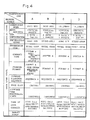
- Fig. 4 illustrates an example of communication protocols set in the communication protocol storage memory 24 of ID controller 20.
- Four types of communication protocols A, B, C and D are exemplified. The contents of each communication protocol are divided into a physical level and data link level.
- the type of communication protocol used by a data carrier which has approached the head 30 is identified by a classification code (the aforementioned A, B, C or D) contained in protocol identification information transmitted by the data carrier.
- the ID controller 20 uses the communication protocol of the type specified by the identified classification code, the ID controller 20 communicates with the data carrier 40 having this protocol.
- the type of data carrier and the memory range in the data link level are contained in the protocol identification information transmitted by the data carrier 40. This information is stored in this table after being received.
- the data carrier 40 includes a modulator/demodulator circuit 41 electromagnetically coupled to the read/write head 30 of the ID controller 20, a decoding circuit 42 for decoding a received signal outputted by the modulator/demodulator circuit 41, a serial input circuit 43, a command decoder 44 for decoding a received command, a data buffer 45 for temporarily storing received data, an EE PROM 46 in which data to be stored is written or from which data is read, a serial output circuit 47 for outputting data read out of the EE PROM 46, and an encoding circuit 48 for encoding the read data before applying the data to the modulator/demodulator circuit 41.
- the writing of data in the EE PROM 46 is so arranged that data can be rewritten in units of e.g. one page (eight bytes) using the data buffer 45.
- the data carrier 40 may have an internal battery for supplying operating power to the various circuits mentioned above, or the operating power may be obtained through the electromagnetic coupling with the head 30. Another option would be for some of the operating power to be supplied by an internal battery and for the rest to be received from the ID controller 20.
- the head 30 of the ID controller 20 includes an oscillator circuit having a coil and sends the transmission data by varying the oscillation frequency of the oscillator circuit or causing the oscillator circuit to oscillate in intermittent fashion.
- the modulator/demodulator circuit 41 of the data carrier 40 includes a resonance circuit having a coil and receives the data in the form of the signal induced in the resonance circuit.
- a signal from an oscillator circuit in the data carrier 40 induces a signal in a resonance circuit possessed by the head 30.
- the load of the oscillator circuit in the head 30 can be changed by varying the resonant frequency of the resonance circuit in data carrier 40.
- the EE PROM 46 of data carrier 40 has an identification information storage area (leading address area 46a, see Fig. 2) in which the communication protocol identification information, namely classification data indicating which communication protocol the data carrier 40 is using, is stored.
- the format of the communication protocol identification information is illustrated in Fig. 5.
- This information includes the protocol classification code, namely codes indicating the distinction among A, B, C and D in Fig. 4, type of data carrier, e.g. read only, read/write, presence or absence of battery, and memory range, namely the address range and memory capacity.
- the transmission speed sensing and synchronizing signal generating circuit 26 of ID controller 20 includes a modulator/demodulator circuit 51, a decoding circuit 52, an encoding circuit 53, a sensing gate circuit 54a for controlling the application of the output signal from decoding circuit 52 to an edge detecting circuit 54, the edge detecting circuit 54, which is for detecting the leading and trailing edges of a pulse signal outputted by the decoding circuit 52, an oscillator 55 for generating a pulse signal having a constant frequency f c , a counter 56 which counts the pulse signals outputted by the oscillator 55, and which is cleared by a detection pulse signal from the edge detecting circuit 54, a latch circuit 57 for latching the count output of the counter 56 each time a detection pulse is outputted by the edge detecting circuit 54, a latch circuit 58 for latching any input signal from the CPU 21 such as a signal representing a value which is one-half the count value indicated by the output data of the latch circuit 57, and a multiplexer
- the operation of the ID controller 20 and data carrier 40 for a case where an auto-read command is supplied by the host controller 10 in the ID system of the illustrated embodiment will now be described with reference to Fig. 8.
- the auto-read command is one which instructs the data in EE PROM 46 accessed by an address contained in the command to be read out of the data carrier 40.
- the ID controller 20 Upon receiving the auto-read command from the host controller 10, the ID controller 20 initially resets the data carrier 40, receives the synchronizing character and the communication protocol identification information from the data carrier 40, identifies the transmission speed, selects the corresponding communication protocol from the memory 24 and thereafter communicates with the data carrier 40 in accordance with the communication protocol. The details of this operation will now be set forth.
- the auto-read command is issued by the host controller 10 at a step ST1.
- the ID controller 20 receives the auto-read command, resulting in a YES decision at a step ST2.
- the ID controller 20 turns off a head drive signal for the read/write head 30 at a step ST3 and resets a data carrier detection flag at a step ST4.
- a step ST5 at which the ID controller 20 turns on the drive signal of the read/write head 30 again and simultaneously turns on a detection gate signal to open the gate 54a.
- the data carrier When the head 30 of the ID controller 20 is turned from off to on, the data carrier receives the oscillating signal from the head 30 if this data carrier 40 draws near the head 30 at this time. This means that the data carrier 40 will be supplied with the operating electric power. In other words, the data carrier 40 attains a state equivalent to that which would be attained by closing a power switch. In response, the data carrier 40 is initially reset and the communication protocol identification information in the leading address area 46a of the EE PROM 46 is read out. The data carrier 40 encodes and transmits the synchronizing character signal and then encodes and transmits the communication protocol identification information (data) that has been read.
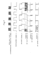
- the synchronizing character signal is composed of eight bits. A portion of this synchronizing character signal received by the ID controller 20 is shown at A in Fig. 7.
- the ID controller 20 detects the transmission speed of the data carrier 40 on the basis of the first few bits of the signal A.
- This detection of the transmission speed is performed by the transmission speed sensing and synchronizing signal generating circuit 26.
- the operation of this circuit will now be described with reference to Figs. 6 and 7.
- the received signal A is inputted to the modulator/demodulator circuit 51 in order to be demodulated into and outputted as a demodulated signal B.
- This demodulated signal is a special signal having on/off times related by the ratio 1:1.
- the demodulated signal is decoded into and outputted as a signal C by the decoding circuit 52.
- the decoded signal C has its leading and trailing edges detected by the edge detecting circuit 54, which outputs a pulse signal E at each leading and trailing edge of the signal C.
- the pulse signal E has a repetition rate corresponding to the transmission speed of the data carrier 40.
- the oscillator 55 oscillates continuously to produce a pulse signal D having a predetermined frequency f c .
- This signal is inputted to the counter 56 and is counted thereby.
- the count recorded in counter 56 is cleared by the output signal E of edge detecting circuit 54, after which the counter 56 is restarted to repeat the counting operation.
- the output signal E of edge detecting circuit 54 also causes the count of counter 56 to be latched in the latch circuit 57. Accordingly, the latch circuit 57 outputs the updated contents of counter 56.
- This counted value C n is a signal conforming to the transmission speed of the data carrier 40.
- the controller 20 thus senses the transmission speed of the data carrier 40.
- the transmission speed has a set value of 9600 BPS or the like. Even if the count C n does not exactly corrrespond to this set value, it will correspond to a value substantially close to the set value and therefore can be regarded as same.
- the CPU 21 of ID controller 20 provides the latch circuit 58 with a value conforming to the count C n , e.g. a value that is one-half of the count.
- the value latched in the latch circuit 58 is applied as a selection signal to the multiplexer 59, which is receiving the count from the counter 56.
- the multiplexer 59 selects a signal representing the prevailing count output and outputs this signal as the synchronizing clock signal.
- the synchronizing clock signal has a waveform the same as that of the demodulated signal B.
- the synchronizing clock signal is applied to the communication control unit 23, as is the decoded signal from the decoding circuit 52.
- the communication control unit 23 reads the inputted decoded signal in synchronization with the synchronizing clock signal, whereby the data transmitted by the data carrier 40 can be discriminated.
- the data transmitted from the ID controller 20 to the data carrier 40 is also expressed by a signal synchronized to the synchronizing clock signal in the communication control unit 23 and is applied to the encoding circuit 53.
- the data is eventually transmitted by the modulator/demodulator circuit 51.
- the ID controller 20 communicates with the data carrier 40 in sync with the clock signal. In other words, the ID controller 20 is capable of communication matched to the transmission speed of the data carrier 40.
- the data carrier 40 transmits the signal representing the communication protocol identification information following the abovementioned synchronizing character signal. Therefore, the communication protocol identification signal is inputted to the communication control unit 23 via the modulator/demodulator circuit 51 and decoding circuit 52. When this identification information is received, the detection flag of data carrier 40 is set. As a result, a YES decision is rendered at a step ST7 in Fig. 8 and the communication protocol identification information received is saved in a buffer or memory at a step ST8. The communication protocol indicated by the protocol classification code in this identification information is selected in memory 24 at a step ST9. Thereafter, the ID controller 20 and the data carrier 40 communicate with each other in accordance with the selected protocol. For example, if B is the protocol of the data carrier 40, data communication is subsequently performed using the communication protocol B in memory 24.
- a step ST10 calls for a determination as to whether the communication protocol indicated by the communication protocol identification information transmitted by the data carrier 40 is set in the memory 24, or in other words, whether this communication protocol is present in the memory 24. If the protocol is present, then the ID controller 20 sends a read command to the data carrier 40 at a step ST11. In response to the read command, the data carrier 40 reads the prescribed data out of the EE PROM 46 and transmits the data to the ID controller 20, thereby performing a read response (step ST12).
- the ID controller 20 If the protocol is not present, namely if the communication protocol identification information sent by the data carrier 40 indicates a communication protocol not present in the memory 24, a NO answer is received at the step ST10 and the ID controller 20 returns an auto-read response indicative of this fact to the host controller 10 at a step ST13. Further, even when the data carrier 40 responds to a normal read response, the ID controller 20 returns an auto-read response indicative of this fact to the host controller 10, as mentioned above.
- the communication protocols classified and defined are of four types, namely A, B, C and D, and the physical level and data link level are as illustrated in Fig. 4.
- definitions and classifications of selectable communication protocols can be selected at will and the invention is not limited to the foregoing embodiment.
Abstract
Description
- This invention relates to an ID system communication control method through which it is possible to control communication between a controller and a plurality of data carriers having different communication protocols.
- ID (identification) systems are available for identifying the types of assembly parts, manufactured parts and semi-fabricated products delivered on a conveyor or the type of tool on a machine tool, by way of example. One type of such an ID system which has recently been considered employs data carrier elements affixed to these articles. Each data carrier contains a memory in which specific data from a controller can be written or from which data can be read. In an ID system of this type, a large number of the data carriers arrive at a single ID controller to have data read or written. This ID system is premised on the fact that the communication between the ID controller and the data carriers will use an identical communication protocol. An ID system having a controller capable of communicating with a plurality of data carriers having different communication protocols has not been proposed heretofore.
- Thus, an ID system in which a controller is capable of communicating with a plurality of data carriers having different communication protocols does not yet exist. However, as ID systems spread and become more common, it is inevitable that data carriers of a variety of types, i.e. of different communication protocols, will appear on the market. Thus, developers of ID systems will be pressed to provide communication control systems in which one and the same controller is capable of communicating with any type of data carrier, regardless of its communication protocol, without imposing limitations upon the data carriers used.
- Accordingly, an object of the present invention is to provide an ID system in which the same controller can communicate with a variety of data carriers even if they have different communication protocols, as well as a method of controlling communication in such an ID system.
- Another object of the present invention is to provide a data carrier and a controller used in the aforementioned ID system.
- A further object of the present invention is to provide a system in which a controller is capable of communicating with a variety of data carriers having different transmission speeds.
- According to the present invention, a method of controlling communication in an ID system in which an exchange of data is carried out between a controller and plural types of data carriers having respective internal memories and different communication protocols comprises the steps of: previously registering the different types of communication protocols of the plurality of data carriers in a memory of the controller in correspondence with classification information of the communication protocols; previously registering in the memory of each data carrier the classification information of its own communication protocol; causing the controller to receive classification information sent by a data carrier at the beginning of communication; causing the controller to select a corresponding communication protocol from its memory using the received classification information; and causing the controller to communicate with the corresponding data carrier in accordance with the selected communication protocol.
- Thus, if a communication protocal is within the range of the plural types of communication protocols registered in the controller memory, the controller will be capable of communicating with any data carrier that arrives regardless of the communication protocol thereof. Accordingly, even if the type of data carrier changes, the original controller can be used without modification. This is advantageous economically.
- When a data carrier is initially reset, the classification information of the communication protocol is sent to the controller. If the data carrier is of the type in which operating power for communication with the controller is supplied by the controller at the time of communication, the controller turns the power supplied to the data carrier from the off state to the on state, thereby initially resetting the data carrier.
- When a data carrier is initially reset, the data carrier sends the controller a synchronizing character signal for deciding the transmission speed of the communication between the data carrier and the controller. In accordance with the present invention, a controller for communicating with a data carrier attached to an article to be identified comprises: means for initially resetting the data carrier; means for receiving and demodulating a modulated synchronizing character signal sent by the data carrier when the data carrier is initially reset; and means for detecting signal transmission speed from the demodulated signal.
- Thus, regardless of the transmission speed of a data carrier, the controller is capable of detecting the transmission speed and producing a synchronizing clock signal. This makes proper communication possible with data carriers having various transmission speeds.
- Other features and advantages of the present invention will be apparent from the following description taken in conjunction with the accompanying drawings.
-
- Fig. 1 is a block diagram illustrating the overall construction of an ID system;
- Fig. 2 is a block diagram illustrating an example of the construction of an ID controller used in the ID system;
- Fig. 3 is a block diagram illustrating an example of the construction of a data carrier used in the ID system;
- Fig. 4 illustrates examples of a plurality of communication protocols registered in a memory of the ID controller;
- Fig. 5 is a view illustrating the format of communication protocol identification information stored in a memory of the data carrier;
- Fig. 6 is a block diagram of circuitry for sensing transmission speed and for generating a synchronizing signal in the ID controller;
- Fig. 7 is a timing chart useful in describing the operation of the transmission speed sensing and synchronizing signal generating circuitry of Fig. 6; and
- Fig. 8 is a flowchart illustrating the overall operation of the ID system, particularly the operation of the ID controller.
- An embodiment of the present invention will now be described in detail with reference to the drawings.
- Fig. 1 is a block diagram illustrating an ID (identification) system embodying the present embodiment.
- The ID system of Fig. 1 includes a
data carrier 40 attached for example, to an assembly conveyed on a conveyor or to a tool on a machine tool. Thedata carrier 40 is composed of a single chip IC and has internal memory means such as an EE PROM. The memory means is adapted to store data conforming to the article to which thedata carrier 40 is attached. In Fig. 1, an arrangement is imagined in which anID controller 20 has a plurality of read/writeheads 30, with a variety of thedata carriers 40 arriving at the read/writeheads 30 in respectively independent systems. The read/writeheads 30 are fixed at suitable locations. When adata carrier 40 arrives near a read/writehead 30, theID controller 20 communicates with thedata carrier 40 via thehead 30. More specifically, in response to a command from ahost controller 10, theID controller 20 acts through the read/writehead 30 to write data into, or read data out of, the memory means of thedata carrier 40 which approaches the read/writehead 30. - As shown in Fig. 2, the
ID controller 20 includes ahost communication interface 22 for communicating with thehost controller 10, aROM 25 for storing a control program for overall control, aCPU 21 for executing a control operation in accordance with the program, acommunication control unit 23 for performing an exchange of data with thedata carriers 40, amemory 24 for storing the contents of a plurality of communication protocols, which are individually possessed by thedata carriers 40, in relation to classification codes (or memory addresses if desired) of the protocols, and a transmission speed sensing and synchronizingsignal generating circuit 26 for detecting the speeds at which data are read out of thedata carriers 40 and for outputting a synchronizing clock signal. In Fig. 2, only onehead 30 is shown for the sake of simplicity. - Fig. 4 illustrates an example of communication protocols set in the communication
protocol storage memory 24 ofID controller 20. Four types of communication protocols A, B, C and D are exemplified. The contents of each communication protocol are divided into a physical level and data link level. The type of communication protocol used by a data carrier which has approached thehead 30 is identified by a classification code (the aforementioned A, B, C or D) contained in protocol identification information transmitted by the data carrier. Using the communication protocol of the type specified by the identified classification code, theID controller 20 communicates with thedata carrier 40 having this protocol. In the table of Fig. 4, the type of data carrier and the memory range in the data link level are contained in the protocol identification information transmitted by thedata carrier 40. This information is stored in this table after being received. - As shown in Fig. 3, the
data carrier 40 includes a modulator/demodulator circuit 41 electromagnetically coupled to the read/writehead 30 of theID controller 20, adecoding circuit 42 for decoding a received signal outputted by the modulator/demodulator circuit 41, aserial input circuit 43, acommand decoder 44 for decoding a received command, adata buffer 45 for temporarily storing received data, anEE PROM 46 in which data to be stored is written or from which data is read, aserial output circuit 47 for outputting data read out of theEE PROM 46, and anencoding circuit 48 for encoding the read data before applying the data to the modulator/demodulator circuit 41. The writing of data in the EEPROM 46 is so arranged that data can be rewritten in units of e.g. one page (eight bytes) using thedata buffer 45. - The
data carrier 40 may have an internal battery for supplying operating power to the various circuits mentioned above, or the operating power may be obtained through the electromagnetic coupling with thehead 30. Another option would be for some of the operating power to be supplied by an internal battery and for the rest to be received from theID controller 20. - The
head 30 of theID controller 20 includes an oscillator circuit having a coil and sends the transmission data by varying the oscillation frequency of the oscillator circuit or causing the oscillator circuit to oscillate in intermittent fashion. The modulator/demodulator circuit 41 of thedata carrier 40 includes a resonance circuit having a coil and receives the data in the form of the signal induced in the resonance circuit. In a case where data is transmitted from thedata carrier 40 to theID controller 20, a signal from an oscillator circuit in thedata carrier 40 induces a signal in a resonance circuit possessed by thehead 30. Alternatively, the load of the oscillator circuit in thehead 30 can be changed by varying the resonant frequency of the resonance circuit indata carrier 40. - The
EE PROM 46 ofdata carrier 40 has an identification information storage area (leadingaddress area 46a, see Fig. 2) in which the communication protocol identification information, namely classification data indicating which communication protocol thedata carrier 40 is using, is stored. The format of the communication protocol identification information is illustrated in Fig. 5. This information includes the protocol classification code, namely codes indicating the distinction among A, B, C and D in Fig. 4, type of data carrier, e.g. read only, read/write, presence or absence of battery, and memory range, namely the address range and memory capacity. - As shown in Fig. 6, the transmission speed sensing and synchronizing
signal generating circuit 26 ofID controller 20 includes a modulator/demodulator circuit 51, adecoding circuit 52, anencoding circuit 53, asensing gate circuit 54a for controlling the application of the output signal from decodingcircuit 52 to anedge detecting circuit 54, theedge detecting circuit 54, which is for detecting the leading and trailing edges of a pulse signal outputted by thedecoding circuit 52, anoscillator 55 for generating a pulse signal having a constant frequency fc, acounter 56 which counts the pulse signals outputted by theoscillator 55, and which is cleared by a detection pulse signal from theedge detecting circuit 54, alatch circuit 57 for latching the count output of thecounter 56 each time a detection pulse is outputted by theedge detecting circuit 54, alatch circuit 58 for latching any input signal from theCPU 21 such as a signal representing a value which is one-half the count value indicated by the output data of thelatch circuit 57, and amultiplexer 59 for selecting an output of thecounter 56 in accordance with the data latched in thelatch circuit 58, and for outputting a synchronizing clock signal. - The operation of the
ID controller 20 anddata carrier 40 for a case where an auto-read command is supplied by thehost controller 10 in the ID system of the illustrated embodiment will now be described with reference to Fig. 8. The auto-read command is one which instructs the data inEE PROM 46 accessed by an address contained in the command to be read out of thedata carrier 40. - Upon receiving the auto-read command from the
host controller 10, theID controller 20 initially resets thedata carrier 40, receives the synchronizing character and the communication protocol identification information from thedata carrier 40, identifies the transmission speed, selects the corresponding communication protocol from thememory 24 and thereafter communicates with thedata carrier 40 in accordance with the communication protocol. The details of this operation will now be set forth. - With reference to Fig. 8, the auto-read command is issued by the
host controller 10 at a step ST1. When this occurs, theID controller 20 receives the auto-read command, resulting in a YES decision at a step ST2. Next, theID controller 20 turns off a head drive signal for the read/write head 30 at a step ST3 and resets a data carrier detection flag at a step ST4. This is followed by a step ST5, at which theID controller 20 turns on the drive signal of the read/write head 30 again and simultaneously turns on a detection gate signal to open thegate 54a. - When the
head 30 of theID controller 20 is turned from off to on, the data carrier receives the oscillating signal from thehead 30 if thisdata carrier 40 draws near thehead 30 at this time. This means that thedata carrier 40 will be supplied with the operating electric power. In other words, thedata carrier 40 attains a state equivalent to that which would be attained by closing a power switch. In response, thedata carrier 40 is initially reset and the communication protocol identification information in the leadingaddress area 46a of theEE PROM 46 is read out. Thedata carrier 40 encodes and transmits the synchronizing character signal and then encodes and transmits the communication protocol identification information (data) that has been read. - The synchronizing character signal is composed of eight bits. A portion of this synchronizing character signal received by the
ID controller 20 is shown at A in Fig. 7. TheID controller 20 detects the transmission speed of thedata carrier 40 on the basis of the first few bits of the signal A. - This detection of the transmission speed is performed by the transmission speed sensing and synchronizing
signal generating circuit 26. The operation of this circuit will now be described with reference to Figs. 6 and 7. - First, the the received signal A is inputted to the modulator/
demodulator circuit 51 in order to be demodulated into and outputted as a demodulated signal B. This demodulated signal is a special signal having on/off times related by the ratio 1:1. The demodulated signal is decoded into and outputted as a signal C by thedecoding circuit 52. The decoded signal C has its leading and trailing edges detected by theedge detecting circuit 54, which outputs a pulse signal E at each leading and trailing edge of the signal C. The pulse signal E has a repetition rate corresponding to the transmission speed of thedata carrier 40. - Meanwhile, the
oscillator 55 oscillates continuously to produce a pulse signal D having a predetermined frequency fc. This signal is inputted to thecounter 56 and is counted thereby. The count recorded incounter 56 is cleared by the output signal E ofedge detecting circuit 54, after which thecounter 56 is restarted to repeat the counting operation. The output signal E ofedge detecting circuit 54 also causes the count ofcounter 56 to be latched in thelatch circuit 57. Accordingly, thelatch circuit 57 outputs the updated contents ofcounter 56. This counted value Cn is a signal conforming to the transmission speed of thedata carrier 40. Thecontroller 20 thus senses the transmission speed of thedata carrier 40. The transmission speed has a set value of 9600 BPS or the like. Even if the count Cn does not exactly corrrespond to this set value, it will correspond to a value substantially close to the set value and therefore can be regarded as same. - The
CPU 21 ofID controller 20 provides thelatch circuit 58 with a value conforming to the count Cn, e.g. a value that is one-half of the count. The value latched in thelatch circuit 58 is applied as a selection signal to themultiplexer 59, which is receiving the count from thecounter 56. At the moment the count fromcounter 56 becomes equal to the value of the selection signal, themultiplexer 59 selects a signal representing the prevailing count output and outputs this signal as the synchronizing clock signal. In this example, the synchronizing clock signal has a waveform the same as that of the demodulated signal B. - The synchronizing clock signal is applied to the
communication control unit 23, as is the decoded signal from thedecoding circuit 52. Thecommunication control unit 23 reads the inputted decoded signal in synchronization with the synchronizing clock signal, whereby the data transmitted by thedata carrier 40 can be discriminated. The data transmitted from theID controller 20 to thedata carrier 40 is also expressed by a signal synchronized to the synchronizing clock signal in thecommunication control unit 23 and is applied to theencoding circuit 53. The data is eventually transmitted by the modulator/demodulator circuit 51. Thus, theID controller 20 communicates with thedata carrier 40 in sync with the clock signal. In other words, theID controller 20 is capable of communication matched to the transmission speed of thedata carrier 40. - The
data carrier 40 transmits the signal representing the communication protocol identification information following the abovementioned synchronizing character signal. Therefore, the communication protocol identification signal is inputted to thecommunication control unit 23 via the modulator/demodulator circuit 51 anddecoding circuit 52. When this identification information is received, the detection flag ofdata carrier 40 is set. As a result, a YES decision is rendered at a step ST7 in Fig. 8 and the communication protocol identification information received is saved in a buffer or memory at a step ST8. The communication protocol indicated by the protocol classification code in this identification information is selected inmemory 24 at a step ST9. Thereafter, theID controller 20 and thedata carrier 40 communicate with each other in accordance with the selected protocol. For example, if B is the protocol of thedata carrier 40, data communication is subsequently performed using the communication protocol B inmemory 24. - A step ST10 calls for a determination as to whether the communication protocol indicated by the communication protocol identification information transmitted by the
data carrier 40 is set in thememory 24, or in other words, whether this communication protocol is present in thememory 24. If the protocol is present, then theID controller 20 sends a read command to thedata carrier 40 at a step ST11. In response to the read command, thedata carrier 40 reads the prescribed data out of theEE PROM 46 and transmits the data to theID controller 20, thereby performing a read response (step ST12). - If the protocol is not present, namely if the communication protocol identification information sent by the
data carrier 40 indicates a communication protocol not present in thememory 24, a NO answer is received at the step ST10 and theID controller 20 returns an auto-read response indicative of this fact to thehost controller 10 at a step ST13. Further, even when thedata carrier 40 responds to a normal read response, theID controller 20 returns an auto-read response indicative of this fact to thehost controller 10, as mentioned above. - In the foregoing embodiment, operation has been described for a case where an auto-read command from the
host controller 10 is inputted to theID controller 20. However, as to whether or not some communication protocol is selected, the invention is not limited to an auto-read command, and operation would be the same if an ordinary read command from thehost controller 10 were applied to theID controller 20. - Further, in the foregoing embodiment, the communication protocols classified and defined are of four types, namely A, B, C and D, and the physical level and data link level are as illustrated in Fig. 4. However, definitions and classifications of selectable communication protocols can be selected at will and the invention is not limited to the foregoing embodiment.
Claims (10)
previously registering the different types of communication protocols of the plurality of data carriers in a memory (24) of said controller in correspondence with classification information of the communication protocols;
previously registering in the memory of each data carrier the classification information of its own communication protocol;
causing said controller to receive classification information sent by a data carrier at the beginning of communication;
causing said controller to select a corresponding communication protocol from its memory using the received classification information; and
causing said controller to communicate with the corresponding data carrier in accordance with the selected communication protocol.
said controller initially resets the data carrier by turning the power supplied thereto from off to on; and
said data carrier transmits communication protocol classification information to said controller when it is initially reset.
a controller (20) which communicates with said data carrier;
said data carrier having a memory (46) storing a classification code indicating its own communication protocol;
said controller including:
a memory (24) for previously storing plural types of communication protocols in correspondence with classification codes thereof;
means (21) operative, when a classification code transmitted by said data carrier is received, for selecting in said memory (24) a communication protocol indicated by the classification code; and
means (21, 23) for controlling execution of communication with said data carrier by using the selected communication protocol.
a memory (46) storing a classification code indicating its own communication protocol; and
means (41, 47, 48) for transmitting a telegraphic message when initially reset, said telegraphic message including a synchronizing character used in order to decide a transmission speed in a communication with said controller, and a classification code read out of said memory.
means (21, 23, 30) for initially resetting the data carrier;
means (30, 51) for receiving and demodulating a modulated synchronizing character signal sent by the data carrier when said data carrier is initially reset; and
means (26, 21) for detecting signal transmission speed from the demodulated signal.
a decoding circuit (52) for decoding the demodulated signal;
an edge detecting circuit (54) for detecting a leading edge and a trailing edge of an output signal from said decoding circuit;
a counter (56) which, from a moment it is reset, counts a pulse signal having a constant frequency, and which is reset by an edge detection output from said edge detecting circuit; and
means (21) for computing transmission speed based on a counted value prevailing immediately prior to resetting of said counter.
Applications Claiming Priority (2)
| Application Number | Priority Date | Filing Date | Title |
|---|---|---|---|
| JP63469/87 | 1987-03-17 | ||
| JP62063469A JPS63228852A (en) | 1987-03-17 | 1987-03-17 | Communication control system for id system |
Publications (3)
| Publication Number | Publication Date |
|---|---|
| EP0282992A2 true EP0282992A2 (en) | 1988-09-21 |
| EP0282992A3 EP0282992A3 (en) | 1991-10-16 |
| EP0282992B1 EP0282992B1 (en) | 1995-09-13 |
Family
ID=13230122
Family Applications (1)
| Application Number | Title | Priority Date | Filing Date |
|---|---|---|---|
| EP88104177A Revoked EP0282992B1 (en) | 1987-03-17 | 1988-03-16 | Method of controlling communication in an ID system |
Country Status (4)
| Country | Link |
|---|---|
| EP (1) | EP0282992B1 (en) |
| JP (1) | JPS63228852A (en) |
| AT (1) | ATE127947T1 (en) |
| DE (1) | DE3854442T2 (en) |
Cited By (18)
| Publication number | Priority date | Publication date | Assignee | Title |
|---|---|---|---|---|
| EP0438250A1 (en) * | 1990-01-16 | 1991-07-24 | Amtech Systems Corporation | System for reading and writing data from and into remote tags |
| EP0461878A2 (en) * | 1990-06-14 | 1991-12-18 | Mitsubishi Denki Kabushiki Kaisha | Non-contact IC card and signal processing method thereof |
| EP0733987A2 (en) * | 1995-03-22 | 1996-09-25 | Kabushiki Kaisha Toshiba | Transmission method of changing protocol and data processing apparatus using this method |
| WO1996030857A1 (en) * | 1995-03-31 | 1996-10-03 | Cybermark, L.L.C. | Intelligent card reader having emulation features |
| EP0753822A2 (en) * | 1995-07-12 | 1997-01-15 | Ilco Unican, Inc. | Transponder detector |
| DE19601511C1 (en) * | 1996-01-17 | 1997-08-21 | Pronet Netzwerkloesungen Fuer | Data card reader parameter setting method using amplitude loading modulation |
| WO1999046722A1 (en) * | 1998-03-11 | 1999-09-16 | Dassault At | Method, system and device for transferring, by electromagnetic linkage, data between readers and nomadic objects |
| FR2776148A1 (en) * | 1998-03-11 | 1999-09-17 | Dassault Automatismes | Universal card reader for communicating with cards or badges by electromagnetic linkage |
| WO1999048039A1 (en) * | 1998-03-20 | 1999-09-23 | Mastercard International, Inc. | Method and device for selecting a reconfigurable communications protocol between an ic card and a terminal |
| US5959276A (en) * | 1993-04-12 | 1999-09-28 | Kabushiki Kaisha Toshiba | Issuing customized IC cards of different types |
| WO1999053401A2 (en) * | 1998-04-15 | 1999-10-21 | Bull Cp8 | Chip card comprising means for managing a virtual memory, associated communication method and protocol |
| WO2001050407A1 (en) * | 2000-01-06 | 2001-07-12 | Samsys Incorporated | A system for multi-standard rfid tags |
| EP1191474A2 (en) * | 2000-09-21 | 2002-03-27 | Kabushiki Kaisha Toshiba | Portable electronic apparatus and communication method of portable electronic apparatus |
| US6578768B1 (en) | 1998-03-20 | 2003-06-17 | Mastercard International Incorporated | Method and device for selecting a reconfigurable communications protocol between and IC card and a terminal |
| EP0727759B1 (en) * | 1995-02-20 | 2004-08-18 | Kabushiki Kaisha Toshiba | IC card reader/writer |
| EP1793325A2 (en) * | 1993-03-10 | 2007-06-06 | Avid Identification Systems, Inc. | Multi-mode identification system |
| NL2002273C2 (en) * | 2008-12-02 | 2010-06-03 | Amb I T Holding B V | DETECTION SYSTEM INCLUDING A DETECTION DEVICE FOR MULTIPLE APPLICATIONS AND ONE OR MORE TRANSPONDERS. |
| EP3158542A1 (en) * | 2014-06-23 | 2017-04-26 | Legic Identsystems AG | Electronic access control device and access control method |
Families Citing this family (1)
| Publication number | Priority date | Publication date | Assignee | Title |
|---|---|---|---|---|
| JPH0290840A (en) * | 1988-09-28 | 1990-03-30 | Hitachi Ltd | Data communication system |
Citations (7)
| Publication number | Priority date | Publication date | Assignee | Title |
|---|---|---|---|---|
| US4471345A (en) * | 1982-03-05 | 1984-09-11 | Sensormatic Electronics Corporation | Randomized tag to portal communication system |
| DE3307579A1 (en) * | 1983-03-03 | 1984-11-29 | Jürgen Dipl.-Ing. 8017 Ebersberg Machate | DEVICE FOR CONTACTLY INQUIRING A RELATED DATA CARRIER |
| US4501958A (en) * | 1981-03-05 | 1985-02-26 | Electronique Marcel Dassault | Verification system, for example for passing through a toll point |
| EP0155662A2 (en) * | 1984-03-21 | 1985-09-25 | MAHO WERKZEUGMASCHINENBAU BABEL & CO. | Tool holder with a data carrier for tool identification |
| DE3523554A1 (en) * | 1984-08-24 | 1986-03-06 | Peter L. Ing.(grad.) 8084 Inning Ortloff | Device for contactlessly controlling a conveying, sorting and/or processing plant |
| EP0176933A2 (en) * | 1984-09-27 | 1986-04-09 | Tokyo Electric Co., Ltd. | Bar code reading apparatus |
| DD235745A1 (en) * | 1985-03-28 | 1986-05-14 | Deutfracht Seereederei Rostock | DEVICE FOR RECEIVING GUARANTEES IN FREIGHT TRUCK |
-
1987
- 1987-03-17 JP JP62063469A patent/JPS63228852A/en active Pending
-
1988
- 1988-03-16 AT AT88104177T patent/ATE127947T1/en not_active IP Right Cessation
- 1988-03-16 DE DE3854442T patent/DE3854442T2/en not_active Revoked
- 1988-03-16 EP EP88104177A patent/EP0282992B1/en not_active Revoked
Patent Citations (7)
| Publication number | Priority date | Publication date | Assignee | Title |
|---|---|---|---|---|
| US4501958A (en) * | 1981-03-05 | 1985-02-26 | Electronique Marcel Dassault | Verification system, for example for passing through a toll point |
| US4471345A (en) * | 1982-03-05 | 1984-09-11 | Sensormatic Electronics Corporation | Randomized tag to portal communication system |
| DE3307579A1 (en) * | 1983-03-03 | 1984-11-29 | Jürgen Dipl.-Ing. 8017 Ebersberg Machate | DEVICE FOR CONTACTLY INQUIRING A RELATED DATA CARRIER |
| EP0155662A2 (en) * | 1984-03-21 | 1985-09-25 | MAHO WERKZEUGMASCHINENBAU BABEL & CO. | Tool holder with a data carrier for tool identification |
| DE3523554A1 (en) * | 1984-08-24 | 1986-03-06 | Peter L. Ing.(grad.) 8084 Inning Ortloff | Device for contactlessly controlling a conveying, sorting and/or processing plant |
| EP0176933A2 (en) * | 1984-09-27 | 1986-04-09 | Tokyo Electric Co., Ltd. | Bar code reading apparatus |
| DD235745A1 (en) * | 1985-03-28 | 1986-05-14 | Deutfracht Seereederei Rostock | DEVICE FOR RECEIVING GUARANTEES IN FREIGHT TRUCK |
Cited By (36)
| Publication number | Priority date | Publication date | Assignee | Title |
|---|---|---|---|---|
| EP0438250A1 (en) * | 1990-01-16 | 1991-07-24 | Amtech Systems Corporation | System for reading and writing data from and into remote tags |
| EP0461878A2 (en) * | 1990-06-14 | 1991-12-18 | Mitsubishi Denki Kabushiki Kaisha | Non-contact IC card and signal processing method thereof |
| EP0461878A3 (en) * | 1990-06-14 | 1997-07-02 | Mitsubishi Electric Corp | Non-contact ic card and signal processing method thereof |
| EP1793325A2 (en) * | 1993-03-10 | 2007-06-06 | Avid Identification Systems, Inc. | Multi-mode identification system |
| EP1793325A3 (en) * | 1993-03-10 | 2009-12-09 | Avid Identification Systems, Inc. | Multi-mode identification system |
| US5959276A (en) * | 1993-04-12 | 1999-09-28 | Kabushiki Kaisha Toshiba | Issuing customized IC cards of different types |
| EP0727759B1 (en) * | 1995-02-20 | 2004-08-18 | Kabushiki Kaisha Toshiba | IC card reader/writer |
| EP0733987A2 (en) * | 1995-03-22 | 1996-09-25 | Kabushiki Kaisha Toshiba | Transmission method of changing protocol and data processing apparatus using this method |
| EP0733987A3 (en) * | 1995-03-22 | 1997-11-12 | Kabushiki Kaisha Toshiba | Transmission method of changing protocol and data processing apparatus using this method |
| WO1996030857A1 (en) * | 1995-03-31 | 1996-10-03 | Cybermark, L.L.C. | Intelligent card reader having emulation features |
| US5679945A (en) * | 1995-03-31 | 1997-10-21 | Cybermark, L.L.C. | Intelligent card reader having emulation features |
| US6223984B1 (en) | 1995-03-31 | 2001-05-01 | Cybermark, Inc. | Distinct smart card reader having wiegand, magnetic strip and bar code types emulation output |
| EP0753822A3 (en) * | 1995-07-12 | 1999-02-03 | Ilco Unican, Inc. | Transponder detector |
| EP0753822A2 (en) * | 1995-07-12 | 1997-01-15 | Ilco Unican, Inc. | Transponder detector |
| DE19601511C1 (en) * | 1996-01-17 | 1997-08-21 | Pronet Netzwerkloesungen Fuer | Data card reader parameter setting method using amplitude loading modulation |
| FR2776147A1 (en) * | 1998-03-11 | 1999-09-17 | Dassault Automatismes | Universal card reader for communicating with cards or badges by electromagnetic linkage |
| FR2776148A1 (en) * | 1998-03-11 | 1999-09-17 | Dassault Automatismes | Universal card reader for communicating with cards or badges by electromagnetic linkage |
| US6505771B1 (en) | 1998-03-11 | 2003-01-14 | Dassault At | Method, system and device for transferring, by electromagnetic linkage, data between readers and nomadic objects |
| WO1999046722A1 (en) * | 1998-03-11 | 1999-09-16 | Dassault At | Method, system and device for transferring, by electromagnetic linkage, data between readers and nomadic objects |
| AU765190B2 (en) * | 1998-03-11 | 2003-09-11 | Thales | Method, system and device for transferring, by electromagnetic linkage, data between readers and nomadic objects |
| WO1999048039A1 (en) * | 1998-03-20 | 1999-09-23 | Mastercard International, Inc. | Method and device for selecting a reconfigurable communications protocol between an ic card and a terminal |
| US6578768B1 (en) | 1998-03-20 | 2003-06-17 | Mastercard International Incorporated | Method and device for selecting a reconfigurable communications protocol between and IC card and a terminal |
| AU764307B2 (en) * | 1998-03-20 | 2003-08-14 | Mastercard International Incorporated | Method and device for selecting a reconfigurable communications protocol between an IC card and a terminal |
| WO1999053401A2 (en) * | 1998-04-15 | 1999-10-21 | Bull Cp8 | Chip card comprising means for managing a virtual memory, associated communication method and protocol |
| WO1999053401A3 (en) * | 1998-04-15 | 1999-12-29 | Bull Cp8 | Chip card comprising means for managing a virtual memory, associated communication method and protocol |
| US6687800B1 (en) | 1998-04-15 | 2004-02-03 | Bull Cp8 | Chip card comprising means and method for managing a virtual memory and associated communication method |
| WO2001050407A1 (en) * | 2000-01-06 | 2001-07-12 | Samsys Incorporated | A system for multi-standard rfid tags |
| US6617962B1 (en) | 2000-01-06 | 2003-09-09 | Samsys Technologies Inc. | System for multi-standard RFID tags |
| US7116212B2 (en) | 2000-01-06 | 2006-10-03 | Sirit Technologies Inc. | System for multi-standard RFID tags |
| US7196613B2 (en) | 2000-01-06 | 2007-03-27 | Sirit Technologies Inc. | System for multi-standard RFID tags |
| US6714999B2 (en) | 2000-09-21 | 2004-03-30 | Kabushiki Kaisha Toshiba | Portable electronic apparatus and communication method for protocol selection processing of a portable electronic apparatus |
| EP1191474A3 (en) * | 2000-09-21 | 2003-01-22 | Kabushiki Kaisha Toshiba | Portable electronic apparatus and communication method of portable electronic apparatus |
| EP1191474A2 (en) * | 2000-09-21 | 2002-03-27 | Kabushiki Kaisha Toshiba | Portable electronic apparatus and communication method of portable electronic apparatus |
| NL2002273C2 (en) * | 2008-12-02 | 2010-06-03 | Amb I T Holding B V | DETECTION SYSTEM INCLUDING A DETECTION DEVICE FOR MULTIPLE APPLICATIONS AND ONE OR MORE TRANSPONDERS. |
| EP2194483A1 (en) * | 2008-12-02 | 2010-06-09 | AMB i.t. Holding B.V. | A detection system comprising a detection device for a number of applications and one or more transponders |
| EP3158542A1 (en) * | 2014-06-23 | 2017-04-26 | Legic Identsystems AG | Electronic access control device and access control method |
Also Published As
| Publication number | Publication date |
|---|---|
| EP0282992B1 (en) | 1995-09-13 |
| DE3854442T2 (en) | 1996-05-30 |
| ATE127947T1 (en) | 1995-09-15 |
| JPS63228852A (en) | 1988-09-22 |
| EP0282992A3 (en) | 1991-10-16 |
| DE3854442D1 (en) | 1995-10-19 |
Similar Documents
| Publication | Publication Date | Title |
|---|---|---|
| US4924210A (en) | Method of controlling communication in an ID system | |
| EP0282992B1 (en) | Method of controlling communication in an ID system | |
| JP4713491B2 (en) | Method and apparatus for identifying a device | |
| EP1256083B1 (en) | Electronic label reading system | |
| JP3867251B2 (en) | Method for transmitting data in a radio frequency identification system | |
| US7609147B2 (en) | Method and apparatus for improving wireless data transmission | |
| US7893815B2 (en) | Method for selecting one or several transponders | |
| US20110183635A1 (en) | Contactless integrated circuit card with real-time protocol switching function and card system including the same | |
| EP0217654B1 (en) | Information medium | |
| JPH0573694A (en) | Portable field-programmable detecting plate | |
| JP2001527725A (en) | Reader for radio frequency identification system | |
| US7286041B2 (en) | Maintenance of an anticollision channel in an electronic identification system | |
| KR20020010095A (en) | Card system, ic card and card reader/writer used for the card system | |
| JP2000101472A (en) | Communication system | |
| CN100437622C (en) | Method for activating a communication mode of a peer communication unit | |
| US8111672B2 (en) | Method for data communication between a base station and a transponder | |
| CN111865362A (en) | Data exchange in a dynamic transponder, and corresponding transponder | |
| US6697419B1 (en) | Digital transmission method | |
| JPS63221950A (en) | Article discriminating system | |
| JP2560660B2 (en) | Item identification system | |
| KR920004358B1 (en) | Reproducing/recording method and apparatus thereof using p.p.m. method | |
| JPS63228854A (en) | Communication controller for id system | |
| US6328218B1 (en) | Electronic card identification methods | |
| JPH0454751A (en) | Commodity identification system | |
| JP3608233B2 (en) | Mobile object identification device |
Legal Events
| Date | Code | Title | Description |
|---|---|---|---|
| PUAI | Public reference made under article 153(3) epc to a published international application that has entered the european phase |
Free format text: ORIGINAL CODE: 0009012 |
|
| 17P | Request for examination filed |
Effective date: 19880316 |
|
| AK | Designated contracting states |
Kind code of ref document: A2 Designated state(s): AT BE CH DE ES FR GB GR IT LI LU NL SE |
|
| PUAL | Search report despatched |
Free format text: ORIGINAL CODE: 0009013 |
|
| AK | Designated contracting states |
Kind code of ref document: A3 Designated state(s): AT BE CH DE ES FR GB GR IT LI LU NL SE |
|
| 17Q | First examination report despatched |
Effective date: 19920316 |
|
| GRAA | (expected) grant |
Free format text: ORIGINAL CODE: 0009210 |
|
| AK | Designated contracting states |
Kind code of ref document: B1 Designated state(s): AT BE CH DE ES FR GB GR IT LI LU NL SE |
|
| PG25 | Lapsed in a contracting state [announced via postgrant information from national office to epo] |
Ref country code: IT Free format text: LAPSE BECAUSE OF FAILURE TO SUBMIT A TRANSLATION OF THE DESCRIPTION OR TO PAY THE FEE WITHIN THE PRESCRIBED TIME-LIMIT;WARNING: LAPSES OF ITALIAN PATENTS WITH EFFECTIVE DATE BEFORE 2007 MAY HAVE OCCURRED AT ANY TIME BEFORE 2007. THE CORRECT EFFECTIVE DATE MAY BE DIFFERENT FROM THE ONE RECORDED. Effective date: 19950913 Ref country code: AT Effective date: 19950913 Ref country code: BE Effective date: 19950913 Ref country code: CH Effective date: 19950913 Ref country code: LI Effective date: 19950913 Ref country code: GR Free format text: LAPSE BECAUSE OF FAILURE TO SUBMIT A TRANSLATION OF THE DESCRIPTION OR TO PAY THE FEE WITHIN THE PRESCRIBED TIME-LIMIT Effective date: 19950913 |
|
| REF | Corresponds to: |
Ref document number: 127947 Country of ref document: AT Date of ref document: 19950915 Kind code of ref document: T |
|
| REF | Corresponds to: |
Ref document number: 3854442 Country of ref document: DE Date of ref document: 19951019 |
|
| ET | Fr: translation filed | ||
| PG25 | Lapsed in a contracting state [announced via postgrant information from national office to epo] |
Ref country code: ES Free format text: LAPSE BECAUSE OF FAILURE TO SUBMIT A TRANSLATION OF THE DESCRIPTION OR TO PAY THE FEE WITHIN THE PRESCRIBED TIME-LIMIT Effective date: 19951214 |
|
| REG | Reference to a national code |
Ref country code: CH Ref legal event code: PL |
|
| PGFP | Annual fee paid to national office [announced via postgrant information from national office to epo] |
Ref country code: NL Payment date: 19960322 Year of fee payment: 9 |
|
| PG25 | Lapsed in a contracting state [announced via postgrant information from national office to epo] |
Ref country code: LU Free format text: LAPSE BECAUSE OF NON-PAYMENT OF DUE FEES Effective date: 19960331 |
|
| PLBI | Opposition filed |
Free format text: ORIGINAL CODE: 0009260 |
|
| PLBQ | Unpublished change to opponent data |
Free format text: ORIGINAL CODE: EPIDOS OPPO |
|
| PLAB | Opposition data, opponent's data or that of the opponent's representative modified |
Free format text: ORIGINAL CODE: 0009299OPPO |
|
| PLBF | Reply of patent proprietor to notice(s) of opposition |
Free format text: ORIGINAL CODE: EPIDOS OBSO |
|
| 26 | Opposition filed |
Opponent name: GIESECKE & DEVRIENT GMBH Effective date: 19960613 |
|
| R26 | Opposition filed (corrected) |
Opponent name: GIESECKE & DEVRIENT GMBH Effective date: 19960613 |
|
| NLR1 | Nl: opposition has been filed with the epo |
Opponent name: GIESECKE & DEVRIENT GMBH |
|
| PLBF | Reply of patent proprietor to notice(s) of opposition |
Free format text: ORIGINAL CODE: EPIDOS OBSO |
|
| PLBF | Reply of patent proprietor to notice(s) of opposition |
Free format text: ORIGINAL CODE: EPIDOS OBSO |
|
| PG25 | Lapsed in a contracting state [announced via postgrant information from national office to epo] |
Ref country code: NL Effective date: 19971001 |
|
| NLV4 | Nl: lapsed or anulled due to non-payment of the annual fee |
Effective date: 19971001 |
|
| PGFP | Annual fee paid to national office [announced via postgrant information from national office to epo] |
Ref country code: GB Payment date: 20000218 Year of fee payment: 13 |
|
| PGFP | Annual fee paid to national office [announced via postgrant information from national office to epo] |
Ref country code: FR Payment date: 20000316 Year of fee payment: 13 Ref country code: SE Payment date: 20000316 Year of fee payment: 13 |
|
| PGFP | Annual fee paid to national office [announced via postgrant information from national office to epo] |
Ref country code: DE Payment date: 20000330 Year of fee payment: 13 |
|
| RDAH | Patent revoked |
Free format text: ORIGINAL CODE: EPIDOS REVO |
|
| REG | Reference to a national code |
Ref country code: GB Ref legal event code: 746 Effective date: 20000503 |
|
| REG | Reference to a national code |
Ref country code: FR Ref legal event code: D6 |
|
| RDAG | Patent revoked |
Free format text: ORIGINAL CODE: 0009271 |
|
| STAA | Information on the status of an ep patent application or granted ep patent |
Free format text: STATUS: PATENT REVOKED |
|
| 27W | Patent revoked |
Effective date: 20000528 |
|
| GBPR | Gb: patent revoked under art. 102 of the ep convention designating the uk as contracting state |
Free format text: 20000528 |