EP0280766A2 - Method of and installation for electro slag continuous casting of steel and alloys - Google Patents
Method of and installation for electro slag continuous casting of steel and alloys Download PDFInfo
- Publication number
- EP0280766A2 EP0280766A2 EP87114823A EP87114823A EP0280766A2 EP 0280766 A2 EP0280766 A2 EP 0280766A2 EP 87114823 A EP87114823 A EP 87114823A EP 87114823 A EP87114823 A EP 87114823A EP 0280766 A2 EP0280766 A2 EP 0280766A2
- Authority
- EP
- European Patent Office
- Prior art keywords
- slag
- mold
- electrically conductive
- liquid
- heated
- Prior art date
- Legal status (The legal status is an assumption and is not a legal conclusion. Google has not performed a legal analysis and makes no representation as to the accuracy of the status listed.)
- Withdrawn
Links
Images
Classifications
-
- B—PERFORMING OPERATIONS; TRANSPORTING
- B22—CASTING; POWDER METALLURGY
- B22D—CASTING OF METALS; CASTING OF OTHER SUBSTANCES BY THE SAME PROCESSES OR DEVICES
- B22D11/00—Continuous casting of metals, i.e. casting in indefinite lengths
- B22D11/10—Supplying or treating molten metal
- B22D11/11—Treating the molten metal
-
- C—CHEMISTRY; METALLURGY
- C22—METALLURGY; FERROUS OR NON-FERROUS ALLOYS; TREATMENT OF ALLOYS OR NON-FERROUS METALS
- C22B—PRODUCTION AND REFINING OF METALS; PRETREATMENT OF RAW MATERIALS
- C22B9/00—General processes of refining or remelting of metals; Apparatus for electroslag or arc remelting of metals
- C22B9/16—Remelting metals
- C22B9/18—Electroslag remelting
Abstract
Description
Die Erfindung betrifft ein Verfahren zum kontinuierlichen Gießen von Stählen, insbesondere von Werkzeugstählen, wie beispielsweise Schnellarbeitsstählen, ledeburitischen Cr-Stählen, Stählen für Kalt- und Warmarbeit etc., aus einem Warmhalte- oder Verteilergefäß in eine -- insbesondere wassergekühlte, nach unten offene, gerade oder bogenförmige -- Kokille, aus welcher der teilweise erstarrte Strang kontinuierlich oder schrittweise mittels einer Ausziehvorrichtung abgezogen wird. Zudem erfaßt die Erfindung eine Vorrichtung zur Durchführung dieses Verfahrens.The invention relates to a method for the continuous casting of steels, in particular tool steels, such as, for example, high-speed steels, ledeburitic Cr steels, steels for cold and hot work, etc., from a warming or distribution vessel into a - in particular water-cooled, open at the bottom, straight or curved - mold from which the partially solidified strand is withdrawn continuously or step by means of a pull-out device. The invention also relates to a device for carrying out this method.
Bei der Herstellung von hochlegierten Werkzeugstählen, ledeburitischen Chromstählen und anderen stark seigernden Stählen und Legierungen ist die Herstellung kontinuierlich gegossener Stränge mit kleinen bis mittleren Querschnitten mit Problemen verbunden.In the manufacture of high-alloy tool steels, ledeburitic chrome steels and other strongly segregating steels and alloys, the production of continuously cast strands with small to medium cross sections is associated with problems.
Beim konventionellen Stranggießverfahren müssen nämlich relativ hohe Gießgeschwindigkeiten angewendet werden, um eine annehmbare Oberflächenqualität zu erreichen, die für die Weiterverarbeitung geeignet ist. Die dafür erforderlichen Gießgeschwindigkeiten haben -- zusammen mit der notwendigen Ueberhitzung des Metalls -- Sumpflängen von mehreren Metern zur Folge, die ihrerseits die Ursache für die Ausbildung starker Kernseigerungen, gepaart mit Schwindungshohlräumen sind.In the conventional continuous casting process, relatively high casting speeds have to be used in order to achieve an acceptable surface quality that is suitable for further processing. The casting speeds required for this - together with the necessary overheating of the metal - result in swamp lengths of several meters, which in turn are the cause for the formation of strong nuclear segregations, coupled with shrinkage cavities.
Aus derartigen Gußsträngen hergestellter Stabstahl ist für einen großen Teil der Einsatzfälle nicht verwendbar.Bar steel made from such cast strands cannot be used for a large part of the applications.
Im Gegensatz zum Stranggießen ermöglicht das Elektroschlacke-Umschmelzen selbstverzehrbarer Elektroden die Herstellung von Umschmelzblöcken mit guter Oberfläche bei langsamer Blockaufbaugeschwindigkeit. Die dabei auftretenden geringen Sumpftiefen führen zu einem gleichmäßigen Erstarren zwischen Rand und Kern und damit zu einer guten Innenqualität der umgeschmolzenen Blöcke. Die Anwendung kurzer Kokillen mit absenkbaren Bodenplatten und Elektrodenwechsel erlaubt auch hier die Herstellung relativ langer Stränge. Bei der Herstellung kleiner Abmessungen wird jedoch die Erzeugung der erforderlichen Abschmelzelektroden schwierig, die Verfahrenskosten aufgrund der dann geringen Umschmelzraten werden hoch.In contrast to continuous casting, the electro-slag remelting of self-consumable electrodes enables the production of remelting blocks with a good surface at a slow block build-up speed. The shallow sump depths that occur lead to a uniform solidification between the edge and core and thus to a good internal quality of the remelted blocks. The use of short molds with lowerable base plates and electrode changes also allows the production of relatively long strands. In the production of small dimensions, however, the production of the required consumable electrodes becomes difficult, and the process costs due to the then low remelting rates become high.
Während beim Stranggießen von Formaten zwischen 100 und 200 mm runden oder quadratischen Querschnittes selbst beim langsamen Gießen Gießleistungen von mindestens 5 bis 10 t je Stunde und Strang erforderlich sind, betragen die Abschmelzraten beim ESU-Verfahren maximal 100 bis 200 kg je Stunde bei denselben Formaten. Beim Stranggießen ergeben sich damit Sumpftiefen zwischen 4 und 8 m. Die Sumpftiefen beim ESU-Verfahren betragen dagegen nur 100 bis 300 mm.While continuous casting of formats between 100 and 200 mm round or square cross-section requires casting capacities of at least 5 to 10 t per hour and strand, even with slow casting, the melting rates for the ESU process are a maximum of 100 to 200 kg per hour for the same formats. In continuous casting, swamp depths between 4 and 8 m result. The bottom depths in the ESR process, on the other hand, are only 100 to 300 mm.
Wünschenswert wäre es, Stränge aus hochlegierten Stählen mit gegenüber dem Stranggießen wesentlich geringeren Gießgeschwindigkeiten zu gießen, um eine verbesserte Kernzone zu erreichen, ohne dabei Nachteile hinsichtlich der Ausbildung der Oberfläche aufgrund zu starker Abkühlung in Kauf nehmen zu müssen. Dabei wird vorausgesetzt, daß das flüssige Metall über längere Zeit mit konstanter Temperatur aus einer beheizbaren Pfanne verfügbar gemacht werden kann.It would be desirable to cast strands of high-alloy steels with casting speeds that are significantly lower than those for continuous casting in order to achieve an improved core zone, without having to accept disadvantages with regard to the formation of the surface due to excessive cooling. It is assumed that the liquid metal can be made available from a heated pan at a constant temperature over a long period of time.
Das Hauptproblem beim starken Absenken der Gießgeschwindigkeit beim Stranggießen liegt darin, daß dann die Erstarrung von der Kokillenwand über den Meniskus fortschreitet und es zur Ausbildung von Rillen und Ueberlappungen kommt. Derartige Stränge sind für eine direkte Weiterverarbeitung ungeeignet.The main problem with greatly reducing the casting speed during continuous casting is that the solidification then progresses from the mold wall over the meniscus and grooves and overlaps are formed. Such strands are unsuitable for direct further processing.
Der Erfindung liegt nun die Aufgabe zugrunde, durch geeignete Maßnahmen die jeweiligen Nachteile der oben geschilderten Verfahren zu vermeiden und möglichst deren Vorteile auszunutzen. Ziel ist dabei die kontinuierliche Herstellung von Strängen mit guter Oberfläche bei Gießgeschwindigkeiten, die wesentlich unter denen beim Stranggießen erforderlichen und üblichen liegen, womit auch eine ausreichend gute Kernzone erwartet werden kann.The object of the invention is to avoid the respective disadvantages of the above-described methods by means of suitable measures and, if possible, to utilize their advantages. The aim is the continuous production of strands with a good surface at casting speeds that are significantly lower than those required and customary in continuous casting, which means that a sufficiently good core zone can also be expected.
Zur Lösung dieser Aufgabe führt nun, daß der flüssige Metallspiegel durch eine überhitzte elektrisch leitende flüssige Schlacke vollkommen abgedeckt wird, die Schlacke zusätzlich beheizt und der flüssige Stahl durch die flüssige Schlacke gegossen wird, wobei die Gießgeschwindigkeit so eingestellt wird, daß sie mindestens dem 1,5-fachen der üblichen Umschmelzraten beim Elektroschlackeumschmelzen und maximal 50 % der üblichen Gießgeschwindigkeit beim Stranggießen beträgt.The solution to this problem is that the liquid metal level is completely covered by an overheated, electrically conductive liquid slag, the slag is additionally heated and the liquid steel is poured through the liquid slag, the casting speed being set so that it is at least 1 5 times the usual remelting rates for electroslag remelting and a maximum of 50% of the usual casting speed for continuous casting.
Der Erfinder hat sich zum Absenken der Gießgeschwindigkeit beim Stranggießen die Erkenntnis zunutze gemacht, daß beim Elektroschlacke-Umschmelzen bei noch erheblich geringen Blockaufbaugeschwindigkeiten ausgezeichnete Blockoberflächen erzielbar sind, da die Oberfläche des flüssigen Stahles in der Kokille durch beheizte Schlacke warmgehalten wird, so daß ein Fortschreiten der Erstarrung über den Meniskus verhindert wird.The inventor took advantage of the knowledge to lower the casting speed during continuous casting that excellent block surfaces can be achieved with electro-slag remelting at still considerably low block build-up speeds, since the surface of the liquid steel in the mold is kept warm by heated slag, so that the slag progresses Freezing over the meniscus is prevented.
Erfindungsgemäß sollte die Gießrate in kg/h mindestens gleich sein dem 1,5-fachen des Durchmessers bei Rundsträngen oder der Länge der Seite bei Quadrat bzw. dem Mittel aus der kurzen und langen Seitenlänge bei Rechtecksträngen in mm. Die maximale Gießrate sollte jedoch so niedrig sein, daß eine Tiefe des flüssigen Sumpfes von 4 m nicht überschritten wird.According to the invention, the pouring rate in kg / h should be at least 1.5 times the diameter in the case of round strands or the length of the side in the square or the mean of the short and long side length in the case of rectangular strands in mm. However, the maximum pouring rate should be so low that a depth of the liquid sump of 4 m is not exceeded.
Um eine gleichmäßige Erwärmung des Metallspiegels in der Kokille zu gewährleisten, soll nach einem weiteren Merkmal der Erfindung die Schichtdicke der elektrisch leitenden Schlacke mindestens 20 mm betragen.In order to ensure uniform heating of the metal mirror in the mold, the layer thickness of the electrically conductive slag should be at least 20 mm according to a further feature of the invention.
Die Beheizung der Schlacke kann erfindungsgemäß durch eine oder mehrere nichtverzehrbare Elektroden aus Graphit, Wolfram, Molybdän oder anderen hochschmelzenden elektrisch leitenden Werkstoffen erfolgen, die an eine Stromquelle angeschlossen sind.According to the invention, the slag can be heated by one or more non-consumable electrodes made of graphite, tungsten, molybdenum or other high-melting electrically conductive materials which are connected to a power source.
Anstelle der nichtverzehrbaren Elektroden können auch arteigene verzehrbare Elektroden Verwendung finden. Im prinzip kann das Schlackenbad auch durch einen Plasmabrenner beheizt werden.Instead of the non-consumable electrodes, it is also possible to use electrodes of their own type. In principle, the slag bath can also be heated by a plasma torch.
Grundsätzlich können für die Durchführung des Verfahrens Kokillen, wie sie beim Stranggießen üblich sind, Verwendung finden. Bei der Herstellung von kleinen Querschnitten -- wie beispielsweise 100 mm und darunter -- wird es jedoch schwierig, neben dem Gießstrahl in der Kokille noch eine oder mehrere Elektroden anzuordnen.In principle, molds, as are common in continuous casting, can be used to carry out the method. When producing small cross sections - such as 100 mm and less - it becomes difficult to arrange one or more electrodes in addition to the pouring stream in the mold.
Dieses Problem kann durch den Einsatz an sich bekannter, nach oben erweiterter Trichterkokillen gelöst werden. Beim Gießen wird der Spiegel des Metalls erfindungsgemäß im unteren engen Teil gehalten, während die Schlacke bis in den erweiterten oberen Teil reicht, wo dann ausreichend Platz für die Anordnung der Elektroden besteht.This problem can be solved by using funnel molds which are known per se and are expanded at the top. When casting, the mirror of the metal is held in the lower narrow part according to the invention, while the slag extends into the enlarged upper part, where there is then sufficient space for the arrangement of the electrodes.
Für die Anordnung der Elektroden sind im Rahmen der Erfindung verschiedene Möglichkeiten denkbar, die in den Patentansprüchen beschrieben sind.Various possibilities are conceivable for the arrangement of the electrodes within the scope of the invention, which are described in the patent claims.
Während ein Pol durch eine in die in der Kokille befindlichen Schlacke eintauchende Elektrode gebildet wird, kann der zweite Pol an den abgezogenen Strang gelegt werden.While one pole is formed by an electrode immersed in the slag in the mold, the second pole can be placed on the stripped strand.
Der zweite Pol kann auch durch das aus einem vorgeschalteten Verteiler laufende flüssige Metall gebildet werden, wobei die Stromzufuhr dazu über in die Verteilerwand eingebaute Elektroden zu erfolgen vermag.The second pole can also be formed by the liquid metal running from an upstream distributor, the power supply being able to do this via electrodes built into the distributor wall.
Eine andere Möglichkeit besteht darin, auch den Verteiler mit einer elektrisch leitenden Schlacke abzudecken und auch dort die Stromzufuhr über eine in die Schlacke eintauchende Elektrode herzustellen.Another possibility is to also cover the distributor with an electrically conductive slag and also to produce the power supply there via an electrode immersed in the slag.
Der zweite Pol kann aber auch durch eine zweite in das Schlackenbad in der Kokille eintauchende Elektrode gebildet werden.However, the second pole can also be formed by a second electrode immersed in the slag bath in the mold.
Der Strangabzug aus der Kokille kann kontinuierlich oder schrittweise erfolgen.The strand can be withdrawn from the mold continuously or step by step.
Ueblicherweise wird bei feststehender Kokille ein schrittweiser Strangabzug gewählt, wobei an jeden Abzugsschritt ein Rückhubschritt angeschlossen werden kann.Usually, a step-by-step strand withdrawal is selected when the mold is stationary, and a return stroke step can be connected to each withdrawal step.
Wird mit kontinuierlichem Strangabzug gearbeitet, so führt die Kokille eine oszillirende Bewegung in der Weise aus, daß bei Bewegung in Strangabzugsrichtung der Strang kurzfristig von der Kokille überholt wird.If continuous strand withdrawal is used, the mold carries out an oscillating movement in such a way that the strand is briefly overtaken by the mold when moving in the strand withdrawal direction.
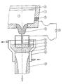
Weitere Vorteile, Merkmale und Einzelheiten der Erfindung ergeben sich aus der nachfolgenden Beschreibung eines bevorzugten Ausführungsbeispiels sowie anhand der Zeichnung. Deren einzige Figur zeigt einen Teillängsschnitt durch eine Vorrichtung.Further advantages, features and details of the invention result from the following description of a preferred exemplary embodiment and from the drawing. The only figure shows a partial longitudinal section through a device.
Aus einem ausgemauerten Verteilergefäß 1, in welchem sich unter einer Deckschicht aus Abdeckschlacke 2 flüssiges Metall 3 befindet, läuft ein Gießstrahl 4 aus einem Ausguß 5 in eine wassergekühlte nach unten offene Trichterkokille 6. In dieser überlagert einen Metallspiegel 7 eines Stranges 12 eine elektrisch leitende, überhitzte Schlacke 8, in welche eine rohrförmige Graphitelektrode 9 eintaucht. Diese ist an eine Stromquelle 10 angeschlossen.A
Der zweite Pol der Stromquelle 10 liegt einer im Verteiler eingebauten Elektrode 11, von wo der Stromfluß über das flüssige Metall 3 in die Trichterkokille 6 und durch die Schlacke 8 zur Graphitelektrode 9 läuft. Der in der Trichterkokille 6 gebildete Strang 12 wird nach unten abgezogen.The second pole of the
Claims (10)
dadurch gekennzeichnet,
daß der flüssige Metallspiegel durch eine überhitzte elektrisch leitende flüssige Schlacke vollkommen abgedeckt wird, die Schlacke zusätzlich beheizt und der flüssige Stahl durch die flüssige Schlacke gegossen wird, wobei die Gießgeschwindigkeit so eingestellt wird, daß sie mindestens dem 1,5-fachen der üblichen Umschmelzraten beim Elektroschlackeumschmelzen und maximal 50 % der üblichen Gießgeschwindigkeit beim Stranggießen beträgt.1. Process for the continuous casting of steels, in particular tool steels, such as high-speed steels, ledeburitic Cr steels, steels for cold and hot work, etc., from a holding or distribution vessel into a mold, from which the partially solidified strand is produced continuously or step by step is pulled off by means of a pull-out device,
characterized,
that the liquid metal level is completely covered by an overheated, electrically conductive liquid slag, the slag is additionally heated and the liquid steel is poured through the liquid slag, the casting speed being set so that it is at least 1.5 times the usual remelting rates at Electro-slag remelting and a maximum of 50% of the usual casting speed for continuous casting.
Applications Claiming Priority (2)
| Application Number | Priority Date | Filing Date | Title |
|---|---|---|---|
| AT463/87 | 1987-03-03 | ||
| AT46387A AT399463B (en) | 1987-03-03 | 1987-03-03 | METHOD FOR CONTINUOUSLY CASTING ELECTRIC STEEL AND ALLOYS |
Publications (2)
| Publication Number | Publication Date |
|---|---|
| EP0280766A2 true EP0280766A2 (en) | 1988-09-07 |
| EP0280766A3 EP0280766A3 (en) | 1989-02-22 |
Family
ID=3491291
Family Applications (1)
| Application Number | Title | Priority Date | Filing Date |
|---|---|---|---|
| EP87114823A Withdrawn EP0280766A3 (en) | 1987-03-03 | 1987-10-10 | Method of and installation for electro slag continuous casting of steel and alloys |
Country Status (3)
| Country | Link |
|---|---|
| EP (1) | EP0280766A3 (en) |
| AT (1) | AT399463B (en) |
| DE (1) | DE3734339A1 (en) |
Cited By (5)
| Publication number | Priority date | Publication date | Assignee | Title |
|---|---|---|---|---|
| EP0786531A1 (en) * | 1996-01-29 | 1997-07-30 | Inteco Internationale Technische Beratung Gesellschaft mbH | Process and installation for remelting of metals to a strand |
| AT406239B (en) * | 1996-04-09 | 2000-03-27 | Inteco Int Techn Beratung | Water-cooled mould for continuous casting or electroslag remelting |
| CN102089101A (en) * | 2008-07-04 | 2011-06-08 | 阿勒里斯铝业科布伦茨有限公司 | Method for casting a composite ingot |
| CN102941323A (en) * | 2012-12-12 | 2013-02-27 | 济钢集团有限公司 | Method for quickly replacing tundish at low liquid level of medium thin plate blank continuous casting machine crystallizer |
| CN110548840A (en) * | 2019-10-09 | 2019-12-10 | 辽宁科技大学 | device and method for adding heated solid-state covering slag into crystallizer in continuous casting process |
Families Citing this family (1)
| Publication number | Priority date | Publication date | Assignee | Title |
|---|---|---|---|---|
| AT408528B (en) | 1999-06-08 | 2001-12-27 | Inteco Int Techn Beratung | METHOD AND DEVICE FOR THE CONTINUOUS PRODUCTION OF MOLDED OR MELTED STRANDS BY AN ELECTROSLACK METHOD |
Citations (2)
| Publication number | Priority date | Publication date | Assignee | Title |
|---|---|---|---|---|
| DE2449812A1 (en) * | 1973-11-08 | 1975-05-15 | Voest Ag | PROCESS FOR CONTINUOUS CASTING OF STEEL BARS, IN PARTICULAR SLABS, IN A CONTINUOUS CASTING PLANT |
| DE2941508A1 (en) * | 1978-10-12 | 1980-04-30 | Nippon Steel Corp | METHOD FOR CONTINUOUSLY CASTING SLABS FOR THE PRODUCTION OF CORNORIENTED ELECTRIC STEEL SHEETS AND STRIPS |
Family Cites Families (4)
| Publication number | Priority date | Publication date | Assignee | Title |
|---|---|---|---|---|
| DE1483646A1 (en) * | 1965-06-11 | 1969-09-25 | Suedwestfalen Ag Stahlwerke | Method and device for the production of cast blocks, preferably steel blocks |
| FR1513573A (en) * | 1967-01-06 | 1968-02-16 | Soc Metallurgique Imphy | Method and device for refining metal in a continuous casting plant |
| SE332833B (en) * | 1968-06-27 | 1977-09-19 | Asea Ab | KOKILL FOR MANUFACTURE OF GOODS FROM STEEL AND METAL ALLOYS BY THE ELECTROSIQUE GRAGINATION METHOD |
| SE364648B (en) * | 1970-12-04 | 1974-03-04 | Asea Ab |
-
1987
- 1987-03-03 AT AT46387A patent/AT399463B/en not_active IP Right Cessation
- 1987-10-10 EP EP87114823A patent/EP0280766A3/en not_active Withdrawn
- 1987-10-12 DE DE19873734339 patent/DE3734339A1/en not_active Withdrawn
Patent Citations (2)
| Publication number | Priority date | Publication date | Assignee | Title |
|---|---|---|---|---|
| DE2449812A1 (en) * | 1973-11-08 | 1975-05-15 | Voest Ag | PROCESS FOR CONTINUOUS CASTING OF STEEL BARS, IN PARTICULAR SLABS, IN A CONTINUOUS CASTING PLANT |
| DE2941508A1 (en) * | 1978-10-12 | 1980-04-30 | Nippon Steel Corp | METHOD FOR CONTINUOUSLY CASTING SLABS FOR THE PRODUCTION OF CORNORIENTED ELECTRIC STEEL SHEETS AND STRIPS |
Cited By (8)
| Publication number | Priority date | Publication date | Assignee | Title |
|---|---|---|---|---|
| EP0786531A1 (en) * | 1996-01-29 | 1997-07-30 | Inteco Internationale Technische Beratung Gesellschaft mbH | Process and installation for remelting of metals to a strand |
| AT406384B (en) * | 1996-01-29 | 2000-04-25 | Inteco Int Techn Beratung | METHOD FOR ELECTROSHELL STRAND MELTING OF METALS |
| AT406239B (en) * | 1996-04-09 | 2000-03-27 | Inteco Int Techn Beratung | Water-cooled mould for continuous casting or electroslag remelting |
| CN102089101A (en) * | 2008-07-04 | 2011-06-08 | 阿勒里斯铝业科布伦茨有限公司 | Method for casting a composite ingot |
| CN102089101B (en) * | 2008-07-04 | 2014-07-09 | 阿勒里斯铝业科布伦茨有限公司 | Method for casting a composite ingot |
| CN102941323A (en) * | 2012-12-12 | 2013-02-27 | 济钢集团有限公司 | Method for quickly replacing tundish at low liquid level of medium thin plate blank continuous casting machine crystallizer |
| CN110548840A (en) * | 2019-10-09 | 2019-12-10 | 辽宁科技大学 | device and method for adding heated solid-state covering slag into crystallizer in continuous casting process |
| CN110548840B (en) * | 2019-10-09 | 2024-04-02 | 辽宁科技大学 | Device and method for adding heating solid-state protecting slag into crystallizer in continuous casting process |
Also Published As
| Publication number | Publication date |
|---|---|
| DE3734339A1 (en) | 1988-09-15 |
| EP0280766A3 (en) | 1989-02-22 |
| ATA46387A (en) | 1994-10-15 |
| AT399463B (en) | 1995-05-26 |
Similar Documents
| Publication | Publication Date | Title |
|---|---|---|
| DE1296747B (en) | Device for supplying a metallic melt from a storage container | |
| DE2702061A1 (en) | COCILLE FOR ELECTRIC SLASK MELTING OF METAL BLOCKS WITH EDGE PROFILE | |
| DE19654021C2 (en) | Process for remelting metals into a strand and device therefor | |
| EP0280766A2 (en) | Method of and installation for electro slag continuous casting of steel and alloys | |
| DE1483646A1 (en) | Method and device for the production of cast blocks, preferably steel blocks | |
| DE2355249A1 (en) | BLOCK CASTING FORM, IN PARTICULAR FOR BLOCK CASTING FOR ELECTRIC SLASK | |
| AT410413B (en) | METHOD FOR ELECTROSHELL MELTING OF METALS | |
| DE1608082C3 (en) | Device for refining steel medium »slag in a continuous casting mold | |
| DE2804487C2 (en) | Device for filling the block heads of cast metal blocks using the electroslag remelting process | |
| DE69912105T2 (en) | DEVICE FOR FOUNDING METAL | |
| DE2941849A1 (en) | METHOD FOR PRODUCING CONSTRUCTION PARTS BY ELECTROSWAG WELDING | |
| EP1257675B1 (en) | Method and arrangement for producing hollow moulded bodies from metal | |
| DE2807844C2 (en) | Method of electro-slag casting of metal blocks | |
| DE2257104C3 (en) | Device for electroslag melting of mold blocks | |
| EP0229589B1 (en) | Device and process for continuous casting of metals | |
| DE2215860C3 (en) | Electro-slag remelting plant for remelting self-consuming electrodes | |
| DE1057291B (en) | Process and device for arc melting of metals in a continuous casting mold in twin design | |
| AT345488B (en) | DEVICE FOR THE SIMULTANEOUS PRODUCTION OF SEVERAL BLOCKS BY ELECTRIC MELTING | |
| DE2605645C3 (en) | Method and device for electroslag remelting | |
| DE2420141C3 (en) | Method and device for electroslag remelting | |
| DE1583687C3 (en) | Process for the production of metal blocks with different cross-sections in sections | |
| AT345486B (en) | PROCESS AND DEVICE FOR ELECTRIC SLAG REMOVAL OF METALS OR METAL ALLOYS | |
| DE1952010C3 (en) | Plant for electroslag pouring hollow metal blocks | |
| DE2113521A1 (en) | Electroslag remelting process and device for its implementation | |
| AT266358B (en) | Method of casting metal blocks |
Legal Events
| Date | Code | Title | Description |
|---|---|---|---|
| PUAI | Public reference made under article 153(3) epc to a published international application that has entered the european phase |
Free format text: ORIGINAL CODE: 0009012 |
|
| AK | Designated contracting states |
Kind code of ref document: A2 Designated state(s): AT BE CH DE ES FR GB GR IT LI LU NL SE |
|
| RBV | Designated contracting states (corrected) |
Designated state(s): AT BE CH DE ES FR GB IT LI LU SE |
|
| PUAL | Search report despatched |
Free format text: ORIGINAL CODE: 0009013 |
|
| AK | Designated contracting states |
Kind code of ref document: A3 Designated state(s): AT BE CH DE ES FR GB IT LI LU SE |
|
| 17P | Request for examination filed |
Effective date: 19890425 |
|
| 17Q | First examination report despatched |
Effective date: 19890915 |
|
| 18W | Application withdrawn |
Withdrawal date: 19900512 |
|
| STAA | Information on the status of an ep patent application or granted ep patent |
Free format text: STATUS: THE APPLICATION HAS BEEN WITHDRAWN |
|
| R18W | Application withdrawn (corrected) |
Effective date: 19900512 |
|
| RIN1 | Information on inventor provided before grant (corrected) |
Inventor name: HOLZGRUBER, WOLFGANG, DIPL.-ING. DR. MONT. Inventor name: HAISSIG, MANFRED, DIPL.-ING. |