EP0280633A1 - Machine for removing silage blocks from a silo - Google Patents
Machine for removing silage blocks from a silo Download PDFInfo
- Publication number
- EP0280633A1 EP0280633A1 EP88440007A EP88440007A EP0280633A1 EP 0280633 A1 EP0280633 A1 EP 0280633A1 EP 88440007 A EP88440007 A EP 88440007A EP 88440007 A EP88440007 A EP 88440007A EP 0280633 A1 EP0280633 A1 EP 0280633A1
- Authority
- EP
- European Patent Office
- Prior art keywords
- eccentrics
- machine according
- knives
- pins
- supports
- Prior art date
- Legal status (The legal status is an assumption and is not a legal conclusion. Google has not performed a legal analysis and makes no representation as to the accuracy of the status listed.)
- Granted
Links
Images


Classifications
-
- B—PERFORMING OPERATIONS; TRANSPORTING
- B23—MACHINE TOOLS; METAL-WORKING NOT OTHERWISE PROVIDED FOR
- B23D—PLANING; SLOTTING; SHEARING; BROACHING; SAWING; FILING; SCRAPING; LIKE OPERATIONS FOR WORKING METAL BY REMOVING MATERIAL, NOT OTHERWISE PROVIDED FOR
- B23D49/00—Machines or devices for sawing with straight reciprocating saw blades, e.g. hacksaws
- B23D49/003—Machines or devices for sawing with straight reciprocating saw blades, e.g. hacksaws having a plurality of saw blades or saw blades having plural cutting zones
- B23D49/006—Machines or devices for sawing with straight reciprocating saw blades, e.g. hacksaws having a plurality of saw blades or saw blades having plural cutting zones with contiguous, oppositely reciprocating saw blades
-
- A—HUMAN NECESSITIES
- A01—AGRICULTURE; FORESTRY; ANIMAL HUSBANDRY; HUNTING; TRAPPING; FISHING
- A01F—PROCESSING OF HARVESTED PRODUCE; HAY OR STRAW PRESSES; DEVICES FOR STORING AGRICULTURAL OR HORTICULTURAL PRODUCE
- A01F25/00—Storing agricultural or horticultural produce; Hanging-up harvested fruit
- A01F25/16—Arrangements in forage silos
- A01F25/20—Unloading arrangements
- A01F25/2027—Unloading arrangements for trench silos
- A01F25/2036—Cutting or handling arrangements for silage blocks
-
- B—PERFORMING OPERATIONS; TRANSPORTING
- B23—MACHINE TOOLS; METAL-WORKING NOT OTHERWISE PROVIDED FOR
- B23D—PLANING; SLOTTING; SHEARING; BROACHING; SAWING; FILING; SCRAPING; LIKE OPERATIONS FOR WORKING METAL BY REMOVING MATERIAL, NOT OTHERWISE PROVIDED FOR
- B23D51/00—Sawing machines or sawing devices working with straight blades, characterised only by constructional features of particular parts; Carrying or attaching means for tools, covered by this subclass, which are connected to a carrier at both ends
- B23D51/16—Sawing machines or sawing devices working with straight blades, characterised only by constructional features of particular parts; Carrying or attaching means for tools, covered by this subclass, which are connected to a carrier at both ends of drives or feed mechanisms for straight tools, e.g. saw blades, or bows
Definitions
- the present invention relates to machines for removing blocks of fodder from a substantially horizontal silo comprising in particular a chassis provided at its lower part with spikes and, at a certain distance above these spikes, an arm or a rail carrying a movable cutting device for cutting blocks.
- This cutting device comprises one or more knives which are animated during cutting.
- the cutting device comprises two knives, each of which is fixed to a slide subjected to rectilinear movements.
- each slide is connected by means of an eccentric to a drive motor and is guided near each of its ends by means of rollers. These are located on either side of the slides and engage in grooves provided in their sides.
- the rectilinear guide of the slides carrying the knives has several drawbacks. Due to the play that is created between the slides and their guide rollers, said slides and the knives adopt during cutting a slightly inclined position relative to the vertical. As a result, the lower part of the knives is set back from the upper part, which also results in deviations of the knives, especially in the angles of their trajectory.
- the present invention aims to overcome the aforementioned drawbacks of known machines. It must in particular simplify the cutting device, facilitate the cutting of the products and improve the guiding of the knives.
- an important characteristic of the invention consists in that each knife is fixed on a support which is mounted free in rotation on eccentric parts of trunnions each rotating around its longitudinal axis during work.
- This arrangement makes it possible to animate the knives with a rotary movement around said pins.
- the knives advance alternately in the silo so that there is constantly only the width of a knife to clear.
- the force required for their advance is thus less than that required for the advance of knives of known machines. Thanks to the reduction of the pressures exerted on the knives, these undergo less deformation and remain on their normal trajectory.
- the means for guiding and driving the knife supports are extremely simple and inexpensive.
- said means do not require operating clearances, which makes it possible to have particularly precise knife guiding.
- the pins on which the knife supports are mounted are interconnected by means of a member ensuring a positive connection.
- This connection can for example be achieved by means of a toothed belt, a chain or connecting rods.
- the values of the eccentricity of the eccentrics of the pins of the same knife support are different. This characteristic makes it possible, for example, to vary the displacement of the lower part of the corresponding knife with respect to its upper part.
- the cutting device comprises three animated knives. These knives are arranged side by side and are fixed on supports mounted on pins provided with eccentrics. The eccentrics of the three knife supports are offset between them by angles of about 120 °. Due to this offset, there is constantly at least one knife in the cutting phase. This provides a continuous cut and a regular feed.
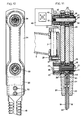
- the machine according to the invention comprises in particular a frame (1) forming a rigid frame.
- This chassis (1) has three coupling points for coupling to a not shown drive tractor. These coupling points consist of two lower yokes (2) and an upper yoke (3).
- Said chassis is also provided at its lower part with several points (4) which extend in a substantially horizontal plane.
- a support arm (5) carrying at its outer end a cutting device (6). The latter is articulated on said arm by means of a substantially vertical axis (7).
- the support arm (5) of the cutting device (6) is articulated in a housing (8) by means of a substantially vertical axis of which only the geometric axis (9) is shown in FIG. 1.
- This housing (8) is itself articulated on a substantially vertical axis (10) which is fixed to a plate (11) integral with the chassis (1).
- a toothed crown (12) which meshes with a rack (13) fixed on the body of a hydraulic cylinder (14) with double rod secured to the chassis (1).
- each of the above two axes (9 and 10) carries a toothed wheel. These two wheels communicate with each other by means of an intermediate toothed wheel also housed in the housing (8).
- the movement of the cutting head (6) for cutting a block is obtained by moving longitudinally the cylinder body (14) and the rack (13). This then rotates the housing (8) around the axis (10), which housing in turn moves the support arm (5). This movement of the support arm (5) takes place in the direction opposite to the direction of rotation of the housing (8) due to the arrangement of the aforementioned toothed wheels.
- the speed of rotation of the support arm (5) on its axis of articulation with the housing (8) is equal to four thirds of the speed of rotation of said housing on its axis (10). This arrangement makes it possible to move the cutting device (6) along a U-shaped trajectory for the cutting of substantially rectangular blocks.
- the cutting device (6) is oriented around the articulation axis (7) with the support arm (5) in order to keep it constantly tangent to its path. This orientation is ensured by means of a rod (15) articulated on the cutting device (6) and connected to a second rod (16) which is controlled by a crank (17) connected to the support housing (8) by a pin. crossing the axis of articulation of the support arm (5).
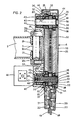
- the cutting device (6) comprises two toothed knives (18 and 19) which extend downwards practically to the level of the points (4) of the chassis (1).
- Each of these knives (18, 19) is fixed to a support (20, 21) by means of screws (22).
- These supports (20 and 21) are mainly located in a housing (23) constituted by a wall (24) and a cover (25) which can be fixed to said wall by means of screws.
- This wall (24) has on its face opposite the cover (25) two tabs (26 and 27) each having a cutout (28) in which is housed the hinge pin (7) mentioned above.
- said axis is fixed to the wall (24) by means of screws (29). It is also guided in a bore (30) of the arm (5) using needle bearings (31).
- each pin (33, 34) consists of a cylindrical body (36) provided with two eccentrics (37 and 38). The latter are positioned on these cylindrical bodies using spacers or washers (39) and are blocked by means of shoulders (40) which are provided at one end of said cylindrical bodies and nuts (41 ) which are screwed onto threaded parts of their other ends.
- pins (33 and 34) can rotate around their longitudinal axes (49 and 50) during cutting. To this end, they are guided in bores (42) in the wall (24) of the housing (23) by means of bearings (43) with two rows of angular contact balls. They extend horizontally and are directed perpendicular to the cutting plane of the knives (18 and 19).
- each support (20 and 21) of the knives (18 and 19) is mounted on the same pins (33 and 34). There are two of these, each located near one of the ends of said supports.
- each support (20 and 21) has near its two ends bores (44) in which are housed the ball bearings (35) used for their mounting on the pins (33 and 34).
- the four eccentrics (37, 38) are substantially identical.
- the two eccentrics (37) of the same support (21) occupy substantially the same position relative to the pins (33 and 34), but are angularly offset by about 180 ° relative to the eccentrics (38) of the other support (20). A good distribution of the masses is thus obtained and therefore smooth operation.
- the lower pin (33) is also connected to the drive shaft (45) of a hydraulic motor (46) fixed to the wall (24). Said connection is ensured by means of grooves (47) of the drive shaft (45) which cooperate with complementary grooves (48) provided in a bore of the journal (33).
- the drive of the supports (20 and 21) and therefore of the knives (18 and 19) is carried out as follows:
- the lower pin (33) is rotated about its longitudinal axis (49) by the hydraulic motor (46).
- the eccentrics (37 and 38) of this pin (33) move the supports (20 and 21) on a circular trajectory whose radius is equal to the value of their eccentricity.
- the upper pin (34) is then also rotated about its longitudinal axis (50) by means of the supports (20 and 21) themselves.
- the two pins (33 and 34) keep the knives (18 and 19) substantially vertical in any position of their trajectory. These knives (18 and 19) in turn cut the ensiled product and clear the passage necessary to advance in the silo.
- the cylindrical body (36) of the lower pin (33) which is connected to the hydraulic motor (46) has grooves (51) on its periphery. These cooperate with complementary grooves provided in the eccentrics (37 and 38). This arrangement ensures a positive connection between said cylindrical body (36) and its eccentrics (37 and 38), in order to avoid relative displacement between these parts.
- the two pins (33 and 34) are also connected by means of a toothed belt (52).
- each has between its two eccentrics (37 and 38) a pulley (53).
- the belt (52) which passes over these two pulleys (53) ensures synchronization of the rotation of the two trunnions (33 and 34) and prevents an indeterminacy of the direction of rotation of the upper trunnion (34) when the supports (20 and 21) are located at the high and low points of their trajectory.
- Said toothed belt can of course be replaced by a chain passing over toothed wheels provided in place of pulleys (53).
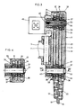
- the mounting of the knives (18 and 19) is practically similar to that of Figure 2 and will not be further described in detail.
- the drive motor (46) is connected to the upper pin (34).
- synchronization between the two pins (33 and 34) is achieved by means of two connecting rods (54 and 55). These are located on either side of the supports (20 and 21).
- Each connecting rod (54, 55) is mounted by means of ball bearings (56) on two eccentrics (57, 58), one of which is integral with the lower journal (33) and the other with the upper journal (34).
- These eccentrics (57 and 58) are similar to those of the supports (20 and 21) of the knives (18 and 19).
- the eccentrics (57) of the connecting rod (54) are angularly offset by about 180 ° relative to those of the other connecting rod (55).
- These eccentrics (57 and 58) of the connecting rods (54 and 55) are moreover angularly offset by approximately 90 ° relative to the eccentrics (37 and 38) of the supports (20 and 21) of the knives (18 and 19). Thanks to this arrangement, there is constantly at least one support (20, 21) or a connecting rod (54, 55) which is located between the two extreme positions of their travel. Therefore, the rotation of the two journals (33 and 34) around their longitudinal axes (49 and 50) remains perfectly synchronized both at start-up and during work. In addition, the use of two connecting rods (54 and 55) ensures good balance of all the moving parts.
- the knives (18 and 19) are also fixed on supports (20 and 21) mounted by means of ball bearings (35) on two pins (33 and 34) provided with 'eccentrics (37 and 38).
- the eccentrics (38) of the support (20) are offset with respect to the eccentrics (37) of the other support (21) by an angle ( ⁇ ) of approximately 160 ° instead of approximately 180 ° as in the examples previous. Thanks to this offset of less than 180 °, the two supports (20 and 21) of the knives (18 and 19) are not located at the same time at the high point and at the low point of their stroke. As a result, the support (20 or 21) which is not at one of the extreme points of its travel, inevitably drives the driven journal (33) in the desired direction. In this embodiment, the synchronization of the rotational movements of the two pins (33 and 34) is ensured by the supports (20 and 21) themselves.
- the value of the eccentricity of the eccentrics (37 and 38) of the upper journal (34) is different from that of the eccentrics (37 and 38) of the lower journal (33). This characteristic makes it possible to vary the trajectory of the knives (18 and 19), in order to improve the cutting and / or the guiding of the latter.
- the supports (20 and 21) of the knives (18 and 19) are displaced by a quarter turn relative to their position in FIG. 7. It appears in particular from said FIG. 8 that the value of the eccentricity of the eccentrics (37 and 38) of the lower journal (33) is approximately equal to four fifths of the value of the eccentricity of the eccentrics (37 and 38) of the upper journal (34). Because of these values, the supports (20) and 21) and the knives (18 and 19) are directed so that the lower ends of said knives meet and simply move on a straight path. They can thus be kept assembled, in a manner known per se, by means of a guide (59). In this arrangement, the vertical displacement of the knives (18 and 19) is defined by the eccentrics (37 and 38) of the lower pin (33).
- a vertical clearance (60) is provided between the supports (20 and 21) and the ball bearings (35) which serve to guide them on the upper pin (34) (FIGS. 7 and 8). Consequently, the bores (44) in which the bearings are mounted ball bearings (35) for guiding on the upper pin (34) are slightly oblong. The value of said clearance is slightly greater than the difference between the values of the eccentricity of the eccentrics (37 and 38) of the upper (34) and lower (33) journals.
- Figures 9 and 10 show another example of mounting the cutting device (6) on the support arm (5).
- the use of only two pins (33 and 34) for guiding and driving the supports (20 and 21) of the knives (18 and 19) allows the hinge pin (7) to be placed with the support arm ( 5) in the cutting plane of the knives (18 and 19). These can thus practically rotate around their longitudinal axis for their orientation, which reduces friction on the ensiled material. Therefore, the progression of the knives (18 and 19) in the silo, in particular in the angles of their trajectory, is considerably facilitated.
- each support (20, 21) of the knives (18 and 19) has between the two bores (44) for their guidance on the pins (33 and 34) a central opening (61).
- the front end of the arm (5) and the hinge pin (7) are placed in these openings (61).
- the cutting device (6) must be engaged on the arm (5) until the latter protrudes from the front side of said device.
- the hinge pin (7) can then be engaged in its housing (30) on the arm (5). Then the device (6) can be brought back towards said axis (7) and be fixed thereon by means of two screws (62). For disassembly, simply proceed in the opposite order.
- FIGs 11 and 12 show an exemplary embodiment with three knives (18, 19 and 63) arranged side by side and which are independent of each other. Each of these knives is fixed on a support (20, 21 and 64) by means of screws (22). The upper end of the central knife (63) projects beyond the other two knives (18 and 19) and is engaged in a groove (65) provided at the lower end of its support (64).
- Each of these supports (20, 21 and 64) is mounted by means of ball bearings (35) on two eccentrics (37, 38 and 66) of journals (33 and 34). These are housed using ball bearings (43) in the rear wall (24).
- Each pin (33, 34) comprises three eccentrics (37, 38 or 66) offset angularly between them by approximately 120 °. The positioning of these eccentrics is ensured by means of grooves (51). They are also blocked on the pins (33, 34) using nuts (41).
- the upper pin (34) is connected to a hydraulic motor (46) which drives the knives (18, 19 and 63).
- the cutting device (6) is connected to the arm (5) by the hinge pin (7).
Abstract
Description
La présente invention se rapporte aux machines pour le prélèvement de blocs de fourrage dans un silo sensiblement horizontal comportant notamment un châssis pourvu à sa partie inférieure de pointes et, à une certaine distance au-dessus de ces pointes, d'un bras ou d'un rail porteur d'un dispositif de coupe déplaçable en vue du découpage de blocs. Ce dispositif de coupe comprend un ou plusieurs couteaux qui sont animés durant la coupe.The present invention relates to machines for removing blocks of fodder from a substantially horizontal silo comprising in particular a chassis provided at its lower part with spikes and, at a certain distance above these spikes, an arm or a rail carrying a movable cutting device for cutting blocks. This cutting device comprises one or more knives which are animated during cutting.
Sur des machines de ce genre connues dans la demande de brevet EP-A-0.081.447, le dispositif de coupe comporte deux couteaux dont chacun est fixé sur un coulisseau soumis à des déplacements rectilignes. Dans ce but, chaque coulisseau est relié par l'intermédiaire d'un excentrique à un moteur d'entraînement et est guidé près de chacune de ses extrémités au moyen de galets. Ceux-ci sont situés de part et d'autre des coulisseaux et s'engagent dans des rainures prévues dans leurs flancs.On machines of this kind known in patent application EP-A-0.081.447, the cutting device comprises two knives, each of which is fixed to a slide subjected to rectilinear movements. For this purpose, each slide is connected by means of an eccentric to a drive motor and is guided near each of its ends by means of rollers. These are located on either side of the slides and engage in grooves provided in their sides.
Sur ce genre d'appareils, les couteaux se déplacent sur une même ligne dans les produits à couper. Par conséquent, ils doivent se dégager ensemble un large passage dans lesdits produits. De ce fait, lorsqu'il s'agit de produits fortement tassés, la puissance nécessaire à cet effet est très importante. Les forces qui s'exercent alors sur les couteaux provoquent souvent des déformations. Celles-ci engendrent des déviations des couteaux de leur trajectoire normale. Elles peuvent aussi causer la casse des couteaux.On this kind of apparatus, the knives move on the same line in the products to be cut. Therefore, they must emerge together a large passage in said products. Therefore, when it comes to heavily packed products, the power required for this purpose is very important. The forces then exerted on the knives often cause deformations. These generate deviations of the knives from their normal trajectory. They can also cause knife breakage.
Par ailleurs, le guidage rectiligne des coulisseaux portant les couteaux présente plusieurs inconvénients. En raison du jeu qui se crée entre les coulisseaux et leurs galets de guidage, lesdits coulisseaux et les couteaux adoptent durant le découpage une position légèrement inclinée par rapport à la verticale. De ce fait, la partie inférieure des couteaux se trouve en retrait par rapport à la partie supérieure, ce qui entraîne également des déviations des couteaux, notamment dans les angles de leur trajectoire.Furthermore, the rectilinear guide of the slides carrying the knives has several drawbacks. Due to the play that is created between the slides and their guide rollers, said slides and the knives adopt during cutting a slightly inclined position relative to the vertical. As a result, the lower part of the knives is set back from the upper part, which also results in deviations of the knives, especially in the angles of their trajectory.
D'autre part, le guidage rectiligne des coulisseaux nécessite que leurs flancs soient usinés et traités. Toutes ces opérations, ainsi que le grand nombre de galets nécessaires pour un tel guidage augmentent considérablement le prix du dispositif de coupe ainsi réalisé.On the other hand, the rectilinear guidance of the slides requires that their sides are machined and treated. All these operations, as well as the large number of rollers necessary for such guidance considerably increase the price of the cutting device thus produced.
La présente invention a pour but d'obvier aux inconvénients précités des machines connues. Elle doit notamment simplifier le dispositif de coupe, faciliter la coupe des produits et améliorer le guidage des couteaux.The present invention aims to overcome the aforementioned drawbacks of known machines. It must in particular simplify the cutting device, facilitate the cutting of the products and improve the guiding of the knives.
A cet effet, une importante caractéristique de l'invention consiste en ce que chaque couteau est fixé sur un support qui est monté libre en rotation sur des parties excentrées de tourillons tournant chacun autour de son axe longitudinal durant le travail.To this end, an important characteristic of the invention consists in that each knife is fixed on a support which is mounted free in rotation on eccentric parts of trunnions each rotating around its longitudinal axis during work.
Cet agencement permet d'animer les couteaux d'un mouvement rotatif autour desdits tourillons. De cette manière, les couteaux avancent alternativement dans le silo de sorte qu'il n'y a constamment que la largeur d'un couteau à dégager. La force nécessaire pour leur avance est ainsi inférieure à celle qu'il faut pour l'avance des couteaux des machines connues. Grâce à la réduction des pressions qui s'exercent sur les couteaux, ceux-ci subissent moins de déformations et restent sur leur trajectoire normale.This arrangement makes it possible to animate the knives with a rotary movement around said pins. In this way, the knives advance alternately in the silo so that there is constantly only the width of a knife to clear. The force required for their advance is thus less than that required for the advance of knives of known machines. Thanks to the reduction of the pressures exerted on the knives, these undergo less deformation and remain on their normal trajectory.
Par ailleurs, les moyens de guidage et d'entraînement des supports des couteaux sont extrêmement simples et d'un coût peu élevé. De plus, lesdits moyens ne nécessitent pas de jeux de fonctionnement, ce qui permet d'avoir un guidage des couteaux particulièrement précis.Furthermore, the means for guiding and driving the knife supports are extremely simple and inexpensive. In addition, said means do not require operating clearances, which makes it possible to have particularly precise knife guiding.
Selon une autre caractéristique de l'invention, les tourillons sur lesquels sont montés les supports des couteaux sont reliés entre eux au moyen d'un organe assurant une liaison positive. De cette manière, on obtient une rotation synchrone desdits tourillons et par conséquent un entraînement régulier des couteaux. Cette liaison peut par exemple être réalisée au moyen d'une courroie crantée, d'une chaîne ou de bielles.According to another characteristic of the invention, the pins on which the knife supports are mounted are interconnected by means of a member ensuring a positive connection. In this way, one obtains a synchronous rotation of said pins and consequently a regular drive of the knives. This connection can for example be achieved by means of a toothed belt, a chain or connecting rods.
Selon une autre caractéristique de l'invention, les valeurs de l'excentricité des excentriques des tourillons d'un même support de couteau sont différentes. Cette caractéristique permet par exemple de faire varier le déplacement de la partie inférieure du couteau correspondant par rapport à sa partie supérieure.According to another characteristic of the invention, the values of the eccentricity of the eccentrics of the pins of the same knife support are different. This characteristic makes it possible, for example, to vary the displacement of the lower part of the corresponding knife with respect to its upper part.
Conformément à une autre caractéristique de l'invention, le dispositif de coupe comporte trois couteaux animés. Ces couteaux sont disposés côte à côte et sont fixés sur des supports montés sur des tourillons munis d'excentriques. Les excentriques des trois supports des couteaux sont décalés entre eux d'angles d'environ 120°. En raison de ce décalage, il y a constamment au moins un couteau dans la phase de coupe. Ceci permet d'obtenir une coupe continue et une avance régulière.According to another characteristic of the invention, the cutting device comprises three animated knives. These knives are arranged side by side and are fixed on supports mounted on pins provided with eccentrics. The eccentrics of the three knife supports are offset between them by angles of about 120 °. Due to this offset, there is constantly at least one knife in the cutting phase. This provides a continuous cut and a regular feed.
D'autres objets et caractéristiques de l'invention ressortiront de la description ci-après, avec référence aux dessins ci-annexés qui représentent, à titre d'exemples non limitatifs, quelques formes de réalisation selon l'invention.Other objects and characteristics of the invention will emerge from the description below, with reference to the appended drawings which represent, by way of nonlimiting examples, some embodiments according to the invention.
Dans ces dessins :
- - La figure 1 représente une vue de côté partiellement en coupe d'une machine selon l'invention,
- - La figure 2 représente une coupe verticale d'un premier exemple de réalisation du dispositif de coupe,
- - La figure 3 représente une coupe similaire à celle de la figure 2 d'un autre exemple de réalisation du dispositif de coupe,
- - La figure 4 représente une coupe selon le plan IV-IV de la figure 3,
- - La figure 5 représents une coupe similaire à celle de la figure 2 d'un autre exemple de réalisation,
- - La figure 6 représente une vue de face du dispositif de la figure 5,
- - La figure 7 représente une coupe verticale d'un autre exemple de réalisation,
- - La figure 8 représente une vue de face du dispositif de la figure 7,
- - La figure 9 représente une coupe verticale d'un autre exemple de réalisation,
- - La figure 10 représente une vue de face du dispositif de la figure 9,
- - La figure 11 représente une coupe verticale d'un autre exemple de réalisation,
- - La figure 12 représente une vue de face du dispositif de la figure 11.
- FIG. 1 represents a partially sectioned side view of a machine according to the invention,
- FIG. 2 represents a vertical section of a first embodiment of the cutting device,
- FIG. 3 represents a section similar to that of FIG. 2 of another exemplary embodiment of the cutting device,
- FIG. 4 represents a section along the plane IV-IV of FIG. 3,
- FIG. 5 represents a section similar to that of FIG. 2 of another exemplary embodiment,
- FIG. 6 represents a front view of the device of FIG. 5,
- FIG. 7 represents a vertical section of another exemplary embodiment,
- FIG. 8 represents a front view of the device of FIG. 7,
- FIG. 9 represents a vertical section of another exemplary embodiment,
- FIG. 10 represents a front view of the device of FIG. 9,
- FIG. 11 represents a vertical section of another exemplary embodiment,
- - Figure 12 shows a front view of the device of Figure 11.
Telle qu'elle est représentée sur la figure 1, la machine selon l'invention comporte notamment un châssis (1) formant un cadre rigide. Ce châssis (1) possède trois points d'accouplement pour l'attelage à un tracteur d'entraînement non représenté. Ces points d'attelage sont constitués par deux chapes inférieures (2) et une chape supérieure (3). Ledit châssis est également pourvu à sa partie inférieure de plusieurs pointes (4) qui s'étendent dans un plan sensiblement horizontal. A une certaine distance au-dessus de ces pointes (4) est prévu un bras support (5) portant à son extrémité extérieure un dispositif de coupe (6). Celui-ci est articulé sur ledit bras au moyen d'un axe sensiblement vertical (7).As shown in Figure 1, the machine according to the invention comprises in particular a frame (1) forming a rigid frame. This chassis (1) has three coupling points for coupling to a not shown drive tractor. These coupling points consist of two lower yokes (2) and an upper yoke (3). Said chassis is also provided at its lower part with several points (4) which extend in a substantially horizontal plane. At a certain distance above these points (4) is provided a support arm (5) carrying at its outer end a cutting device (6). The latter is articulated on said arm by means of a substantially vertical axis (7).
Le bras support (5) du dispositif de coupe (6) est articulé dans un boîtier (8) au moyen d'un axe sensiblement vertical dont seul l'axe géométrique (9) est représenté sur la figure 1. Ce boîtier (8) est lui-même articulé sur un axe sensiblement vertical (10) qui est fixé sur une plaque (11) solidaire du châssis (1). A la base du boîtier (8) est prévue une couronne dentée (12) qui engrène avec une crémaillère (13) fixée sur le corps d'un vérin hydraulique (14) à double tige solidaire du châssis (1). Dans ledit boîtier (8), chacun des deux axes (9 et 10) précités porte une roue dentée. Ces deux roues communiquent entre elles au moyen d'une roue dentée intermédiaire également logée dans le boîtier (8).The support arm (5) of the cutting device (6) is articulated in a housing (8) by means of a substantially vertical axis of which only the geometric axis (9) is shown in FIG. 1. This housing (8) is itself articulated on a substantially vertical axis (10) which is fixed to a plate (11) integral with the chassis (1). At the base of the housing (8) is provided a toothed crown (12) which meshes with a rack (13) fixed on the body of a hydraulic cylinder (14) with double rod secured to the chassis (1). In said housing (8), each of the above two axes (9 and 10) carries a toothed wheel. These two wheels communicate with each other by means of an intermediate toothed wheel also housed in the housing (8).
Le déplacement de la tête de coupe (6) en vue du découpage d'un bloc est obtenu en faisant se déplacer longitudinalement le corps du vérin (14) et la crémaillère (13). Celle-ci fait alors tourner le boîtier (8) autour de l'axe (10), lequel boîtier déplace à son tour le bras support (5). Ce déplacement du bras support (5) s'opère dans la direction opposée au sens de rotation du boîtier (8) en raison de l'agencement des roues dentées précitées. En sus, la vitesse de rotation du bras support (5) sur son axe d'articulation avec le boîtier (8) est égale à quatre tiers de la vitesse de rotation dudit boîtier sur son axe (10). Cet agencement permet de déplacer le dispositif de coupe (6) suivant une trajectoire en forme de U en vue du découpage de blocs sensiblement rectangulaires.The movement of the cutting head (6) for cutting a block is obtained by moving longitudinally the cylinder body (14) and the rack (13). This then rotates the housing (8) around the axis (10), which housing in turn moves the support arm (5). This movement of the support arm (5) takes place in the direction opposite to the direction of rotation of the housing (8) due to the arrangement of the aforementioned toothed wheels. In addition, the speed of rotation of the support arm (5) on its axis of articulation with the housing (8) is equal to four thirds of the speed of rotation of said housing on its axis (10). This arrangement makes it possible to move the cutting device (6) along a U-shaped trajectory for the cutting of substantially rectangular blocks.
Durant ledit découpage, le dispositif de coupe (6) est orienté autour de l'axe d'articulation (7) avec le bras support (5) afin de le maintenir constamment tangent à sa trajectoire. Cette orientation est assurée au moyen d'une tringle (15) articulée sur le dispositif de coupe (6) et reliée à une seconde tringle (16) qui est commandée par une manivelle (17) reliée au boîtier support (8) par un axe traversant l'axe d'articulation du bras support (5).During said cutting, the cutting device (6) is oriented around the articulation axis (7) with the support arm (5) in order to keep it constantly tangent to its path. This orientation is ensured by means of a rod (15) articulated on the cutting device (6) and connected to a second rod (16) which is controlled by a crank (17) connected to the support housing (8) by a pin. crossing the axis of articulation of the support arm (5).
Dans les exemples de réalisation représentés en détail sur les figures 2 à 10, le dispositif de coupe (6) comporte deux couteaux dentés (18 et 19) qui s'étendent vers le bas pratiquement jusqu'au niveau des pointes (4) du châssis (1). Chacun de ces couteaux (18, 19) est fixé sur un support (20, 21) au moyen de vis (22). Ces supports (20 et 21) se situent en grande partie dans un boîtier (23) constitué par une paroi (24) et un couvercle (25) qui peut être fixé sur ladite paroi au moyen de vis. Cette paroi (24) comporte sur sa face opposée au couvercle (25) deux pattes (26 et 27) ayant chacune une découpe (28) dans laquelle est logé l'axe d'articulation (7) précité. Tel que cela ressort de la figure 2, ledit axe est fixé sur la paroi (24) au moyen de vis (29). Il est par ailleurs guidé dans un alésage (30) du bras (5) à l'aide de roulements à aiguilles (31).In the embodiments shown in detail in FIGS. 2 to 10, the cutting device (6) comprises two toothed knives (18 and 19) which extend downwards practically to the level of the points (4) of the chassis (1). Each of these knives (18, 19) is fixed to a support (20, 21) by means of screws (22). These supports (20 and 21) are mainly located in a housing (23) constituted by a wall (24) and a cover (25) which can be fixed to said wall by means of screws. This wall (24) has on its face opposite the cover (25) two tabs (26 and 27) each having a cutout (28) in which is housed the hinge pin (7) mentioned above. As shown in Figure 2, said axis is fixed to the wall (24) by means of screws (29). It is also guided in a bore (30) of the arm (5) using needle bearings (31).
Les supports (20 et 21) des couteaux (18 et 19) sont montés libres en rotation sur des parties excentrées (32) de tourillons (33 et 34) au moyen de roulements à billes (35). Il ressort notamment des vues en coupe que chaque tourillon (33, 34) se compose d'un corps cylindrique (36) muni de deux excentriques (37 et 38). Ces derniers sont positionnés sur ces corps cylindriques à l'aide d'entretoises ou de rondelles (39) et sont bloqués au moyen d'épaulements (40) qui sont prévus à l'une des extrémités desdits corps cylindriques et d'écrous (41) qui se vissent sur des parties filetées de leurs autres extrémités.The supports (20 and 21) of the knives (18 and 19) are freely mounted in rotation on eccentric parts (32) of pins (33 and 34) by means of ball bearings (35). It appears in particular from the sectional views that each pin (33, 34) consists of a cylindrical body (36) provided with two eccentrics (37 and 38). The latter are positioned on these cylindrical bodies using spacers or washers (39) and are blocked by means of shoulders (40) which are provided at one end of said cylindrical bodies and nuts (41 ) which are screwed onto threaded parts of their other ends.
Ces tourillons (33 et 34) peuvent tourner autour de leurs axes longitudinaux (49 et 50) durant le découpage. A cet effet, ils sont guidés dans des alésages (42) de la paroi (24) du boîtier (23) au moyen de roulements (43) à deux rangées de billes à contact angulaire. Ils s'étendent horizontalement et sont dirigés perpendiculairement au plan de coupe des couteaux (18 et 19).These pins (33 and 34) can rotate around their longitudinal axes (49 and 50) during cutting. To this end, they are guided in bores (42) in the wall (24) of the housing (23) by means of bearings (43) with two rows of angular contact balls. They extend horizontally and are directed perpendicular to the cutting plane of the knives (18 and 19).
Dans les exemples représentés, les deux supports (20 et 21) des couteaux (18 et 19) sont montés sur les mêmes tourillons (33 et 34). Ces derniers sont au nombre de deux, chacun se situant près d'une des extrémités desdits supports. A cet effet, chaque support (20 et 21) possède près de ses deux extrémités des alésages (44) dans lesquels sont logés les roulements à billes (35) servant à leur montage sur les tourillons (33 et 34). Les quatre excentriques (37, 38) sont sensiblement identiques. Les deux excentriques (37) d'un même support (21) occupent sensiblement la même position par rapport aux tourillons (33 et 34), mais sont décalés angulairement d'environ 180° par rapport aux excentriques (38) de l'autre support (20). On obtient ainsi une bonne répartition des masses et par conséquent un fonctionnement sans à-coups.In the examples shown, the two supports (20 and 21) of the knives (18 and 19) are mounted on the same pins (33 and 34). There are two of these, each located near one of the ends of said supports. For this purpose, each support (20 and 21) has near its two ends bores (44) in which are housed the ball bearings (35) used for their mounting on the pins (33 and 34). The four eccentrics (37, 38) are substantially identical. The two eccentrics (37) of the same support (21) occupy substantially the same position relative to the pins (33 and 34), but are angularly offset by about 180 ° relative to the eccentrics (38) of the other support (20). A good distribution of the masses is thus obtained and therefore smooth operation.
Le tourillon inférieur (33) est par ailleurs relié à l'arbre d'entraînement (45) d'un moteur hydraulique (46) fixé sur la paroi (24). Ladite liaison est assurée au moyen de cannelures (47) de l'arbre d'entraînement (45) qui coopèrent avec des cannelures complémentaires (48) prévues dans un alésage du tourillon (33).The lower pin (33) is also connected to the drive shaft (45) of a hydraulic motor (46) fixed to the wall (24). Said connection is ensured by means of grooves (47) of the drive shaft (45) which cooperate with complementary grooves (48) provided in a bore of the journal (33).
L'entraînement des supports (20 et 21) et par conséquent des couteaux (18 et 19) s'effectue de la manière suivante : Le tourillon inférieur (33) est entraîné en rotation autour de son axe longitudinal (49) par le moteur hydraulique (46). Les excentriques (37 et 38) de ce tourillon (33) déplacent les supports (20 et 21) sur une trajectoire circulaire dont le rayon est égal à la valeur de leur excentricité. Le tourillon supérieur (34) est alors également mis en rotation autour de son axe longitudinal (50) par l'intermédiaire des supports (20 et 21) eux-mêmes.The drive of the supports (20 and 21) and therefore of the knives (18 and 19) is carried out as follows: The lower pin (33) is rotated about its longitudinal axis (49) by the hydraulic motor (46). The eccentrics (37 and 38) of this pin (33) move the supports (20 and 21) on a circular trajectory whose radius is equal to the value of their eccentricity. The upper pin (34) is then also rotated about its longitudinal axis (50) by means of the supports (20 and 21) themselves.
Les deux tourillons (33 et 34) maintiennent les couteaux (18 et 19) sensiblement verticaux dans n'importe quelle position de leur trajectoire. Ces couteaux (18 et 19) coupent tour à tour le produit ensilé et se dégagent le passage nécessaire pour avancer dans le silo.The two pins (33 and 34) keep the knives (18 and 19) substantially vertical in any position of their trajectory. These knives (18 and 19) in turn cut the ensiled product and clear the passage necessary to advance in the silo.
On constate également sur la figure 2 que le corps cylindrique (36) du tourillon inférieur (33) qui est relié au moteur hydraulique (46) comporte des cannelures (51) sur sa périphérie. Celles-ci coopèrent avec des cannelures complémentaires prévues dans les excentriques (37 et 38). Cet agencement assure une liaison positive entre ledit corps cylindrique (36) et ses excentriques (37 et 38), en vue d'éviter un déplacement relatif entre ces pièces.It can also be seen in FIG. 2 that the cylindrical body (36) of the lower pin (33) which is connected to the hydraulic motor (46) has grooves (51) on its periphery. These cooperate with complementary grooves provided in the eccentrics (37 and 38). This arrangement ensures a positive connection between said cylindrical body (36) and its eccentrics (37 and 38), in order to avoid relative displacement between these parts.
Les deux tourillons (33 et 34) sont par ailleurs reliés au moyen d'une courroie crantée (52). Pour cela, chacun comporte entre ses deux excentriques (37 et 38) une poulie (53). La courroie (52) qui passe sur ces deux poulies (53) assure une synchronisation de la rotation des deux tourillons (33 et 34) et évite une indétermination du sens de rotation du tourillon supérieur (34) lorsque les supports (20 et 21) se situent aux points haut et bas de leur trajectoire. Ladite courroie crantée peut bien entendu être remplacée par une chaîne passant sur des roues dentées prévues à la place de poulies (53).The two pins (33 and 34) are also connected by means of a toothed belt (52). For this, each has between its two eccentrics (37 and 38) a pulley (53). The belt (52) which passes over these two pulleys (53) ensures synchronization of the rotation of the two trunnions (33 and 34) and prevents an indeterminacy of the direction of rotation of the upper trunnion (34) when the supports (20 and 21) are located at the high and low points of their trajectory. Said toothed belt can of course be replaced by a chain passing over toothed wheels provided in place of pulleys (53).
Dans l'exemple des figures 3 et 4, le montage des couteaux (18 et 19) est pratiquement analogue à celui de la figure 2 et ne sera plus décrit en détail. Dans cet exemple, le moteur d'entraînement (46) est relié au tourillon supérieur (34). D'autre part, la synchronisation entre les deux tourillons (33 et 34) est réalisée au moyen de deux bielles (54 et 55). Celles-ci se situent de part et d'autre des supports (20 et 21). Chaque bielle (54, 55) est montée au moyen de roulements à billes (56) sur deux excentriques (57, 58) dont l'un est solidaire du tourillon inférieur (33) et l'autre du tourillon supérieur (34). Ces excentriques (57 et 58) sont semblables à ceux des supports (20 et 21) des couteaux (18 et 19). Les excentriques (57) de la bielle (54) sont décalés angulairement d'environ 180° par rapport à ceux de l'autre bielle (55). Ces excentriques (57 et 58) des bielles (54 et 55) sont par ailleurs décalés angulairement d'environ 90° par rapport aux excentriques (37 et 38) des supports (20 et 21) des couteaux (18 et 19). Grâce à cette disposition, il y a constamment au moins un support (20, 21) ou une bielle (54, 55) qui se situe entre les deux positions extrêmes de leur course. De ce fait, la rotation des deux tourillons (33 et 34) autour de leurs axes longitudinaux (49 et 50) reste parfaitement synchronisée à la fois au démarrage et pendant le travail. En plus, l'utilisation de deux bielles (54 et 55) assure un bon équilibrage de l'ensemble des pièces en mouvement.In the example of FIGS. 3 and 4, the mounting of the knives (18 and 19) is practically similar to that of Figure 2 and will not be further described in detail. In this example, the drive motor (46) is connected to the upper pin (34). On the other hand, synchronization between the two pins (33 and 34) is achieved by means of two connecting rods (54 and 55). These are located on either side of the supports (20 and 21). Each connecting rod (54, 55) is mounted by means of ball bearings (56) on two eccentrics (57, 58), one of which is integral with the lower journal (33) and the other with the upper journal (34). These eccentrics (57 and 58) are similar to those of the supports (20 and 21) of the knives (18 and 19). The eccentrics (57) of the connecting rod (54) are angularly offset by about 180 ° relative to those of the other connecting rod (55). These eccentrics (57 and 58) of the connecting rods (54 and 55) are moreover angularly offset by approximately 90 ° relative to the eccentrics (37 and 38) of the supports (20 and 21) of the knives (18 and 19). Thanks to this arrangement, there is constantly at least one support (20, 21) or a connecting rod (54, 55) which is located between the two extreme positions of their travel. Therefore, the rotation of the two journals (33 and 34) around their longitudinal axes (49 and 50) remains perfectly synchronized both at start-up and during work. In addition, the use of two connecting rods (54 and 55) ensures good balance of all the moving parts.
Dans l'exemple de réalisation des figures 5 et 6, les couteaux (18 et 19) sont également fixés sur des supports (20 et 21) montés au moyen de roulements à billes (35) sur deux tourillons (33 et 34) munis d'excentriques (37 et 38). Les excentriques (38) du support (20) sont décalés par rapport aux excentriques (37) de l'autre support (21) d'un angle (α) d'environ 160° au lieu d'environ 180° comme dans les exemples précédents. Grâce à ce décalage inférieur à 180°, les deux supports (20 et 21) des couteaux (18 et 19) ne se situent pas en même temps au point haut et au point bas de leur course. De ce fait, le support (20 ou 21) qui n'est pas à un des points extrêmes de sa course, entraîne immanquablement le tourillon mené (33) dans la direction voulue. Dans ce mode de réalisation, la synchronisation des mouvements de rotation des deux tourillons (33 et 34) est assurée par les supports (20 et 21) eux-mêmes.In the embodiment of Figures 5 and 6, the knives (18 and 19) are also fixed on supports (20 and 21) mounted by means of ball bearings (35) on two pins (33 and 34) provided with 'eccentrics (37 and 38). The eccentrics (38) of the support (20) are offset with respect to the eccentrics (37) of the other support (21) by an angle (α) of approximately 160 ° instead of approximately 180 ° as in the examples previous. Thanks to this offset of less than 180 °, the two supports (20 and 21) of the knives (18 and 19) are not located at the same time at the high point and at the low point of their stroke. As a result, the support (20 or 21) which is not at one of the extreme points of its travel, inevitably drives the driven journal (33) in the desired direction. In this embodiment, the synchronization of the rotational movements of the two pins (33 and 34) is ensured by the supports (20 and 21) themselves.
Il ressort également de la figure 5 que les corps cylindriques (36) des deux tourillons (33 et 34) comportent sur leur périphérie des cannelures (51) qui coopèrent avec des cannelures complémentaires prévues dans les excentriques (37 et 38). Cet agencement permet d'assurer la position desdits excentriques, même dans les conditions de travail difficiles.It also appears from FIG. 5 that the cylindrical bodies (36) of the two pins (33 and 34) have on their periphery grooves (51) which cooperate with complementary grooves provided in the eccentrics (37 and 38). This arrangement ensures the position of said eccentrics, even in difficult working conditions.
Dans l'exemple de réalisation selon les figures 7 et 8, la valeur de l'excentricité des excentriques (37 et 38) du tourillon supérieur (34) est différente de celle des excentriques (37 et 38) du tourillon inférieur (33). Cette caractéristique permet de faire varier la trajectoire des couteaux (18 et 19), en vue d'améliorer la coupe et/ou le guidage de ces derniers.In the exemplary embodiment according to FIGS. 7 and 8, the value of the eccentricity of the eccentrics (37 and 38) of the upper journal (34) is different from that of the eccentrics (37 and 38) of the lower journal (33). This characteristic makes it possible to vary the trajectory of the knives (18 and 19), in order to improve the cutting and / or the guiding of the latter.
Sur la figure 8, les supports (20 et 21) des couteaux (18 et 19) sont déplacés d'un quart de tour par rapport à leur position sur la figure 7. Il ressort notamment de ladite figure 8 que la valeur de l'excentricité des excentriques (37 et 38) du tourillon inférieur (33) est environ égale à quatre cinquièmes de la valeur de l'excentricité des excentriques (37 et 38) du tourillon supérieur (34). En raison de ces valeurs, les supports (20) et 21) et les couteaux (18 et 19) sont dirigés de telle sorte que les extrémités inférieures desdits couteaux se rejoignent et se déplacent simplement sur une trajectoire rectiligne. On peut ainsi les maintenir assemblés, d'une manière connue en soi, au moyen d'un guide (59). Dans cet agencement, le déplacement vertical des couteaux (18 et 19) est défini par les excentriques (37 et 38) du tourillon inférieur (33). Pour cette raison, il est prévu un jeu vertical (60) entre les supports (20 et 21) et les roulements à billes (35) qui servent à leur guidage sur le tourillon supérieur (34) (figures 7 et 8). Par conséquent, les alésages (44) dans lesquels se montent les roulements à billes (35) pour le guidage sur le tourillon supérieur (34) sont légèrement oblongs. La valeur dudit jeu est légèrement supérieure à la différence entre les valeurs de l'excentricité des excentriques (37 et 38) des tourillons supérieur (34) et inférieur (33).In FIG. 8, the supports (20 and 21) of the knives (18 and 19) are displaced by a quarter turn relative to their position in FIG. 7. It appears in particular from said FIG. 8 that the value of the eccentricity of the eccentrics (37 and 38) of the lower journal (33) is approximately equal to four fifths of the value of the eccentricity of the eccentrics (37 and 38) of the upper journal (34). Because of these values, the supports (20) and 21) and the knives (18 and 19) are directed so that the lower ends of said knives meet and simply move on a straight path. They can thus be kept assembled, in a manner known per se, by means of a guide (59). In this arrangement, the vertical displacement of the knives (18 and 19) is defined by the eccentrics (37 and 38) of the lower pin (33). For this reason, a vertical clearance (60) is provided between the supports (20 and 21) and the ball bearings (35) which serve to guide them on the upper pin (34) (FIGS. 7 and 8). Consequently, the bores (44) in which the bearings are mounted ball bearings (35) for guiding on the upper pin (34) are slightly oblong. The value of said clearance is slightly greater than the difference between the values of the eccentricity of the eccentrics (37 and 38) of the upper (34) and lower (33) journals.
Les valeurs de l'excentricité des excentriques (37 et 38) des tourillons (33 et 34) peuvent être modifiées dans d'autres rapports que celui décrit ci-dessus, sans pour autant sortir du cadre de cette invention.The values of the eccentricity of the eccentrics (37 and 38) of the journals (33 and 34) can be modified in other reports than that described above, without departing from the scope of this invention.
Les figures 9 et 10 représentent un autre exemple de montage du dispositif de coupe (6) sur le bras support (5). L'utilisation de seulement deux tourillons (33 et 34) pour le guidage et l'entraînement des supports (20 et 21) des couteaux (18 et 19) permet de placer l'axe d'articulation (7) avec le bras support (5) dans le plan de coupe des couteaux (18 et 19). Ceux-ci peuvent ainsi pratiquement tourner autour de leur axe longitudinal pour leur orientation, ce qui diminue le frottement sur la matière ensilée. De ce fait, la progression des couteaux (18 et 19) dans le silo, notamment dans les angles de leur trajectoire, est considérablement facilitée.Figures 9 and 10 show another example of mounting the cutting device (6) on the support arm (5). The use of only two pins (33 and 34) for guiding and driving the supports (20 and 21) of the knives (18 and 19) allows the hinge pin (7) to be placed with the support arm ( 5) in the cutting plane of the knives (18 and 19). These can thus practically rotate around their longitudinal axis for their orientation, which reduces friction on the ensiled material. Therefore, the progression of the knives (18 and 19) in the silo, in particular in the angles of their trajectory, is considerably facilitated.
Dans ce mode de réalisation, chaque support (20, 21) des couteaux (18 et 19) comporte entre les deux alésages (44) pour leur guidage sur les tourillons (33 et 34) une ouverture centrale (61). L'extrémité avant du bras (5) et l'axe d'articulation (7) sont placés dans ces ouvertures (61). Pour le montage, il y a lieu d'engager le dispositif de coupe (6) sur le bras (5) jusqu'à ce que ce dernier dépasse sur le côté avant dudit dispositif. L'axe d'articulation (7) peut alors être engagé dans son logement (30) sur le bras (5). Ensuite le dispositif (6) peut être ramené vers ledit axe (7) et être fixé sur celui-ci au moyen des deux vis (62). Pour le démontage, il suffit de procéder dans l'ordre contraire.In this embodiment, each support (20, 21) of the knives (18 and 19) has between the two bores (44) for their guidance on the pins (33 and 34) a central opening (61). The front end of the arm (5) and the hinge pin (7) are placed in these openings (61). For mounting, the cutting device (6) must be engaged on the arm (5) until the latter protrudes from the front side of said device. The hinge pin (7) can then be engaged in its housing (30) on the arm (5). Then the device (6) can be brought back towards said axis (7) and be fixed thereon by means of two screws (62). For disassembly, simply proceed in the opposite order.
L'agencement selon l'invention n'est pas limité à l'emploi de deux couteaux pour la coupe. Les figures 11 et 12 montrent un exemple de réalisation avec trois couteaux (18, 19 et 63) disposés côte à côte et qui sont indépendants entre eux. Chacun de ces couteaux est fixé sur un support (20, 21 et 64) au moyen de vis (22). L'extrémité supérieure du couteau central (63) dépasse les deux autres couteaux (18 et 19) et est engagée dans une rainure (65) prévue à l'extrémité inférieure de son support (64).The arrangement according to the invention is not limited to the use of two knives for cutting. Figures 11 and 12 show an exemplary embodiment with three knives (18, 19 and 63) arranged side by side and which are independent of each other. Each of these knives is fixed on a support (20, 21 and 64) by means of screws (22). The upper end of the central knife (63) projects beyond the other two knives (18 and 19) and is engaged in a groove (65) provided at the lower end of its support (64).
Chacun de ces supports (20, 21 et 64) est monté au moyen de roulements à billes (35) sur deux excentriques (37, 38 et 66) de tourillons (33 et 34). Ceux-ci sont logés à l'aide de roulements à billes (43) dans la paroi arrière (24). Chaque tourillon (33, 34) comporte trois excentriques (37, 38 ou 66) décalés angulairement entre eux d'environ 120°. Le positionnement de ces excentriques est assuré au moyen de cannelures (51). Ils sont par ailleurs bloqués sur les tourillons (33, 34) à l'aide d'écrous (41).Each of these supports (20, 21 and 64) is mounted by means of ball bearings (35) on two eccentrics (37, 38 and 66) of journals (33 and 34). These are housed using ball bearings (43) in the rear wall (24). Each pin (33, 34) comprises three eccentrics (37, 38 or 66) offset angularly between them by approximately 120 °. The positioning of these eccentrics is ensured by means of grooves (51). They are also blocked on the pins (33, 34) using nuts (41).
Il ressort également de la figure 11 que le tourillon supérieur (34) est relié à un moteur hydraulique (46) qui assur l'entraînement des couteaux (18, 19 et 63). Comme dans les exemples décrits précédemment, le dispositif de coupe (6) est relié au bras (5) par l'axe d'articulation (7).It also appears from FIG. 11 that the upper pin (34) is connected to a hydraulic motor (46) which drives the knives (18, 19 and 63). As in the examples described above, the cutting device (6) is connected to the arm (5) by the hinge pin (7).
Grâce au décalage d'environ 120° des trois supports (20, 21 et 64) des couteaux (18, 19 et 63), ils ne se situent jamais ensemble aux deux points extrêmes de leur course. Ils assurent ainsi une rotation synchrone des deux tourillons (33 et 34) en vue d'une coupe régulière. Grâce au grand nombre de couteaux, cet agencement permet aussi une coupe très rapide.Thanks to the approximately 120 ° offset of the three supports (20, 21 and 64) of the knives (18, 19 and 63), they never lie together at the two extreme points of their travel. They thus ensure a synchronous rotation of the two pins (33 and 34) for a regular cut. Thanks to the large number of knives, this arrangement also allows very fast cutting.
Il est bien évident qu'on pourra apporter aux exemples de réalisation décrits ci-dessus divers perfectionnements, modifications ou additions ou remplacer certains éléments par des éléments équivalents, sans pour autant sortir du cadre de la présente invention.It is obvious that we can make the embodiments described above various improvements, modifications or additions or replace certain elements with equivalent elements, without departing from the scope of the present invention.
Claims (19)
Applications Claiming Priority (2)
| Application Number | Priority Date | Filing Date | Title |
|---|---|---|---|
| FR8702185 | 1987-02-16 | ||
| FR8702185A FR2610784B1 (en) | 1987-02-16 | 1987-02-16 | MACHINE FOR TAKING FORAGE BLOCKS FROM A SILO |
Publications (2)
| Publication Number | Publication Date |
|---|---|
| EP0280633A1 true EP0280633A1 (en) | 1988-08-31 |
| EP0280633B1 EP0280633B1 (en) | 1992-04-29 |
Family
ID=9348107
Family Applications (1)
| Application Number | Title | Priority Date | Filing Date |
|---|---|---|---|
| EP19880440007 Expired - Lifetime EP0280633B1 (en) | 1987-02-16 | 1988-02-03 | Machine for removing silage blocks from a silo |
Country Status (3)
| Country | Link |
|---|---|
| EP (1) | EP0280633B1 (en) |
| DE (1) | DE3870483D1 (en) |
| FR (1) | FR2610784B1 (en) |
Citations (7)
| Publication number | Priority date | Publication date | Assignee | Title |
|---|---|---|---|---|
| GB258040A (en) * | 1925-07-15 | 1926-09-16 | Burman & Sons Ltd | Means for cutting hedges and like purposes |
| FR1021857A (en) * | 1950-06-23 | 1953-02-25 | Gema Sa | Apparatus for making slits in wood or similar materials for the introduction of blades of vase plugs and similar parts |
| US3016932A (en) * | 1959-08-18 | 1962-01-16 | John M Jacobson | Power operated saw having oppositely reciprocating blades |
| US3929048A (en) * | 1974-11-11 | 1975-12-30 | John W Mcgehee | Reciprocating gang saw |
| US3978862A (en) * | 1974-08-26 | 1976-09-07 | Stryker Corporation | Surgical cutting device |
| EP0081447A1 (en) * | 1981-12-08 | 1983-06-15 | Kuhn S.A. | Machines for removing blocks of forage from a silo |
| EP0176748A1 (en) * | 1984-09-28 | 1986-04-09 | von der Heide, Hans | Method of and apparatus for cutting compacted crop or silage in particular |
-
1987
- 1987-02-16 FR FR8702185A patent/FR2610784B1/en not_active Expired - Lifetime
-
1988
- 1988-02-03 EP EP19880440007 patent/EP0280633B1/en not_active Expired - Lifetime
- 1988-02-03 DE DE8888440007T patent/DE3870483D1/en not_active Expired - Fee Related
Patent Citations (7)
| Publication number | Priority date | Publication date | Assignee | Title |
|---|---|---|---|---|
| GB258040A (en) * | 1925-07-15 | 1926-09-16 | Burman & Sons Ltd | Means for cutting hedges and like purposes |
| FR1021857A (en) * | 1950-06-23 | 1953-02-25 | Gema Sa | Apparatus for making slits in wood or similar materials for the introduction of blades of vase plugs and similar parts |
| US3016932A (en) * | 1959-08-18 | 1962-01-16 | John M Jacobson | Power operated saw having oppositely reciprocating blades |
| US3978862A (en) * | 1974-08-26 | 1976-09-07 | Stryker Corporation | Surgical cutting device |
| US3929048A (en) * | 1974-11-11 | 1975-12-30 | John W Mcgehee | Reciprocating gang saw |
| EP0081447A1 (en) * | 1981-12-08 | 1983-06-15 | Kuhn S.A. | Machines for removing blocks of forage from a silo |
| EP0176748A1 (en) * | 1984-09-28 | 1986-04-09 | von der Heide, Hans | Method of and apparatus for cutting compacted crop or silage in particular |
Also Published As
| Publication number | Publication date |
|---|---|
| FR2610784B1 (en) | 1990-04-13 |
| DE3870483D1 (en) | 1992-06-04 |
| EP0280633B1 (en) | 1992-04-29 |
| FR2610784A1 (en) | 1988-08-19 |
Similar Documents
| Publication | Publication Date | Title |
|---|---|---|
| FR2598347A1 (en) | CUTTING HEAD AND BLADE FOR CUTTING SHEET MATERIALS | |
| FR2575104A1 (en) | ALTERNATIVE KNIFE MACHINE, PARTICULARLY FOR CUTTING FABRIC STACKS | |
| EP0280633B1 (en) | Machine for removing silage blocks from a silo | |
| EP0191712A2 (en) | Apparatus for injecting a fluid into food products | |
| EP0290105B1 (en) | Device for closing envelopes made of plastic or the like | |
| EP0279760B1 (en) | Machine for removing silage blocks from a silo | |
| EP0320380B1 (en) | Machine for stapling with an oscillating stapler head | |
| EP0071555B1 (en) | Machine for removing blocks of forage from a silo | |
| EP1140467B1 (en) | Tilting mechanism for thermoforming mould with helical cam | |
| CH642020A5 (en) | PACKAGING MACHINE. | |
| EP0152363B1 (en) | Silage block cutting apparatus | |
| EP0162795B1 (en) | Silage block cutter drive | |
| WO1991009539A1 (en) | Method and machine for removing the husk from coconuts | |
| BE519530A (en) | ||
| EP0152364B1 (en) | Silage block cutter transmission | |
| EP0920957A1 (en) | Tangential polishing head for lapping granit and glazed stone | |
| FR2554671A1 (en) | Harvesting machine, particularly for harvesting grapes or for harvesting berries | |
| BE497236A (en) | ||
| FR2546839A1 (en) | Equipment intended to move over the ground step by step | |
| FR2542155A1 (en) | Cutting head and scrub clearing machine comprising such a cutting head | |
| FR2529184A1 (en) | METHOD AND APPARATUS FOR STACKING TAPES | |
| BE498791A (en) | ||
| BE432475A (en) | ||
| BE866087A (en) | SITE SCRAPER | |
| BE432012A (en) |
Legal Events
| Date | Code | Title | Description |
|---|---|---|---|
| PUAI | Public reference made under article 153(3) epc to a published international application that has entered the european phase |
Free format text: ORIGINAL CODE: 0009012 |
|
| AK | Designated contracting states |
Kind code of ref document: A1 Designated state(s): DE FR GB IT NL |
|
| 17P | Request for examination filed |
Effective date: 19890105 |
|
| 17Q | First examination report despatched |
Effective date: 19901019 |
|
| GRAA | (expected) grant |
Free format text: ORIGINAL CODE: 0009210 |
|
| AK | Designated contracting states |
Kind code of ref document: B1 Designated state(s): DE FR GB IT NL |
|
| PG25 | Lapsed in a contracting state [announced via postgrant information from national office to epo] |
Ref country code: IT Free format text: LAPSE BECAUSE OF FAILURE TO SUBMIT A TRANSLATION OF THE DESCRIPTION OR TO PAY THE FEE WITHIN THE PRE;WARNING: LAPSES OF ITALIAN PATENTS WITH EFFECTIVE DATE BEFORE 2007 MAY HAVE OCCURRED AT ANY TIME BEFORE 2007. THE CORRECT EFFECTIVE DATE MAY BE DIFFERENT FROM THE ONE RECORDED.SCRIBED TIME-LIMIT Effective date: 19920429 Ref country code: GB Effective date: 19920429 |
|
| REF | Corresponds to: |
Ref document number: 3870483 Country of ref document: DE Date of ref document: 19920604 |
|
| GBV | Gb: ep patent (uk) treated as always having been void in accordance with gb section 77(7)/1977 [no translation filed] | ||
| PLBE | No opposition filed within time limit |
Free format text: ORIGINAL CODE: 0009261 |
|
| STAA | Information on the status of an ep patent application or granted ep patent |
Free format text: STATUS: NO OPPOSITION FILED WITHIN TIME LIMIT |
|
| 26N | No opposition filed | ||
| PGFP | Annual fee paid to national office [announced via postgrant information from national office to epo] |
Ref country code: DE Payment date: 19990126 Year of fee payment: 12 |
|
| PGFP | Annual fee paid to national office [announced via postgrant information from national office to epo] |
Ref country code: NL Payment date: 19990128 Year of fee payment: 12 |
|
| PGFP | Annual fee paid to national office [announced via postgrant information from national office to epo] |
Ref country code: FR Payment date: 19990225 Year of fee payment: 12 |
|
| PG25 | Lapsed in a contracting state [announced via postgrant information from national office to epo] |
Ref country code: NL Free format text: LAPSE BECAUSE OF NON-PAYMENT OF DUE FEES Effective date: 20000901 |
|
| PG25 | Lapsed in a contracting state [announced via postgrant information from national office to epo] |
Ref country code: FR Free format text: LAPSE BECAUSE OF NON-PAYMENT OF DUE FEES Effective date: 20001031 |
|
| NLV4 | Nl: lapsed or anulled due to non-payment of the annual fee |
Effective date: 20000901 |
|
| PG25 | Lapsed in a contracting state [announced via postgrant information from national office to epo] |
Ref country code: DE Free format text: LAPSE BECAUSE OF NON-PAYMENT OF DUE FEES Effective date: 20001201 |
|
| REG | Reference to a national code |
Ref country code: FR Ref legal event code: ST |