EP0279729B1 - Vehicle for cleaning by spraying and suction of a liquid - Google Patents
Vehicle for cleaning by spraying and suction of a liquid Download PDFInfo
- Publication number
- EP0279729B1 EP0279729B1 EP88400244A EP88400244A EP0279729B1 EP 0279729 B1 EP0279729 B1 EP 0279729B1 EP 88400244 A EP88400244 A EP 88400244A EP 88400244 A EP88400244 A EP 88400244A EP 0279729 B1 EP0279729 B1 EP 0279729B1
- Authority
- EP
- European Patent Office
- Prior art keywords
- liquid
- vehicle
- suction
- cleaning
- spraying
- Prior art date
- Legal status (The legal status is an assumption and is not a legal conclusion. Google has not performed a legal analysis and makes no representation as to the accuracy of the status listed.)
- Expired - Lifetime
Links
Images


Classifications
-
- G—PHYSICS
- G21—NUCLEAR PHYSICS; NUCLEAR ENGINEERING
- G21F—PROTECTION AGAINST X-RADIATION, GAMMA RADIATION, CORPUSCULAR RADIATION OR PARTICLE BOMBARDMENT; TREATING RADIOACTIVELY CONTAMINATED MATERIAL; DECONTAMINATION ARRANGEMENTS THEREFOR
- G21F9/00—Treating radioactively contaminated material; Decontamination arrangements therefor
- G21F9/001—Decontamination of contaminated objects, apparatus, clothes, food; Preventing contamination thereof
-
- E—FIXED CONSTRUCTIONS
- E01—CONSTRUCTION OF ROADS, RAILWAYS, OR BRIDGES
- E01H—STREET CLEANING; CLEANING OF PERMANENT WAYS; CLEANING BEACHES; DISPERSING OR PREVENTING FOG IN GENERAL CLEANING STREET OR RAILWAY FURNITURE OR TUNNEL WALLS
- E01H1/00—Removing undesirable matter from roads or like surfaces, with or without moistening of the surface
- E01H1/10—Hydraulically loosening or dislodging undesirable matter; Raking or scraping apparatus ; Removing liquids or semi-liquids e.g., absorbing water, sliding-off mud
- E01H1/101—Hydraulic loosening or dislodging, combined or not with mechanical loosening or dislodging, e.g. road washing machines with brushes or wipers
- E01H1/103—Hydraulic loosening or dislodging, combined or not with mechanical loosening or dislodging, e.g. road washing machines with brushes or wipers in which the soiled loosening or washing liquid is removed, e.g. by suction
Definitions
- the present invention relates to a cleaning vehicle by spraying and sucking liquid on surfaces, in particular road surfaces.
- Road vehicles operating by sprinkling are well known, in particular in the big cities: they are generally vans or motorcycles provided with a water tank the back of which is installed a means of sprinkling the wheel or the pavement. The cleaning water then flows into the sewers.
- the inventor very correctly arranged the water spraying and suction devices side by side to prevent the water from flowing and dispersing after reaching the ground and to clean the suction device by spraying it part of the water.
- the present invention precisely responds to this problem by combining, on a vehicle, the spraying means for spraying cleaning liquid and means for suctioning the sprayed liquid and henceforth charged with polluting particles, these means being located at the rear of the vehicle, with a device at the front of the vehicle to keep polluting particles in place while waiting for their aspiration.
- the object of the invention is a vehicle for cleaning surfaces comprising a tank of cleaning liquid, a device for projecting the liquid onto the surface to be cleaned, a device for sucking the liquid sprayed towards a second tank.
- the projection and suction devices are located at the rear of the vehicle and in that the vehicle further comprises a device for wetting the surface at the front of the vehicle.
- the devices for projecting and sucking the liquid are generally arranged in two lines oriented transversely to the vehicle.
- the efficiency of the system is improved if the projection and suction devices are isolated from the outside environment by fairings terminated by liquid-tight bands and dragging on the surface to be cleaned.
- FIG. 1 represents a cleaning truck according to the invention which operates on a surface to be cleaned such as a road or a flat concrete area. It comprises a chassis 1 secured to the wheels and a driving cabin 31 as well as a reservoir of clean liquid 2. It supports an assembly constituted in particular by a second reservoir 3 intended to contain the projected and polluted liquid and which is furthermore larger dimensions than the clean liquid tank 2 in order to space out the draining operations as much as possible.
- the second tank 3 communicates with a turbine 4 which creates a vacuum inside. It also communicates, via suction ramps 5 each consisting of a partially flexible pipe, with a suction device generally represented by 6.
- a projection device 7 is contiguous to the suction device 6 and located at the front of it; it communicates by at least one partially flexible projection pipe 8 with the reservoir of clean liquid 2.
- the projection 7 and suction 6 devices extend essentially in the transverse direction of the vehicle, behind it.
- a system composed of a jack 9 and a connecting rod 10 allows in turn to press the suction devices 6 and projection 7 _ which are integral _ on the surface to be cleaned, as shown in Figure 1, or at contrary to bringing them to a rest position according to which they are arranged near the rear wall of the second tank 3.
- a jack 11 makes it possible to tilt the assembly comprising in particular the second tank 3 around a joint 12 at the rear of the truck, which facilitates emptying from the rear of the second tank 3.
- the suction ramps 5 are of reduced length.
- the suction device 6 comprises in particular a rear fairing 16 which promotes suction. It is made of rigid material and is completed by a rear sealing strip 18 between its lower edge and the surface to be cleaned on which it trails. It can be made of rubber or a brush.
- the rear fairing 16 is divided into several contiguous parts extending transversely and each connected to a particular suction ramp 5 and connected to each other by means of articulations of longitudinal axis which allow suction in better conditions. conditions when the surface to be cleaned is curved or hollow.
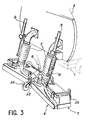
- the articulation can be constituted, as shown in FIG. 3, by a flexible strip 33 which connects two contiguous parts of the rear fairing 16 while allowing their angular movement. Furthermore, rollers 35 are used to limit the lowering of the suction 6 and projection 7 devices.
- Each part of the rear fairing 16 is connected to a front fairing part 17 which isolates projection nozzles 22 from the outside environment.
- the nozzles 22 and the liquid projection hoses 8 are not directly linked to the front fairing 17, but they communicate by ramps 32 which distribute the cleaning liquid from the projection hoses 8 in each of the nozzles 22 located inside the 'the same part of the front fairing 17 and which are integral with it by means of two hinges 23.
- the ramps 32 can thus pivot relative to the front fairing 17, which modifies the orientation of the projection some cash.
- the pivoting can be carried out manually, when the suction 6 and projection 7 devices have been raised from the ground, or automatically by any known means.
- the angle of projection of cleaning liquid on the floor can therefore be adjusted.
- the front fairing 17 may include a front sealing strip 19 which prevents the projection of cleaning liquid towards the front of the vehicle).
- the rear fairing 16 and the front fairing 17 are connected, to each of their parts, by a separation partition 20 which isolates the suction device 6 from the projection device 7 and which is extended at its lower edge by a separation strip 21 stopping a short distance from the surface to be cleaned. This arrangement ensures that the cleaning liquid is not sucked in before touching the surface to be cleaned.
- the number of suction ramps 5 and nozzles 22 arranged in the transverse direction of the vehicle depends only on the width of the surface that is to be cleaned and on the dimensions and configuration of the different parts of the device. It is in particular essential that the nozzles 22 project the liquid over the entire width to be cleaned. In this particular case, two suction ramps 5 and twenty nozzles 22 have been considered.
- FIG. 4 makes it possible to specify the overall constitution of the hydraulic circuit.
- the clean liquid tank 2 contains water which a high pressure pump 26 then projects under pressure to the spray device 7.
- a detergent additive tank 27 is connected to the spray device 7 by means of a metering device 28 which makes it possible to adjust the composition of the cleaning liquid.
- the clean liquid tank 2 is also connected, by means of a low pressure pump 29 and a pipe 36, to a moistening ramp 30 situated at the front of the vehicle near the cabin 31.
- This ramp of moistening 30 is transverse and makes it possible to project by drop nozzles 37 of the droplets of water on the surface which will then be cleaned. The consequence is that the polluting particles are temporarily held in place and much less easily dispersed by the turbulence caused by the wheels and the air circulation that the truck causes. It is this moistening ramp 30 which justifies the installation of the water projection and suction devices at the rear.
- the correct moistening conditions are as follows: the water must be at relatively low pressure, at atmospheric pressure or at slight overpressure to avoid ricochets on the ground, unlike the water projected at the rear which is at a pressure 20 bars leaving the nozzles 22; it is projected at a low flow rate to simply wet the portion of the ground under the truck, and avoid lateral flow as in cleaning vehicles intended for ordinary waste; finally, the water must be projected substantially vertically, with a slight inclination towards the front or towards the rear and without excessive lateral inclination towards the outside so as not to push the polluting particles out of the reach of the rear cleaning device.
- the moistening nozzles 37 project continuous streams of water at a rate of a few liters per minute.
Landscapes
- Engineering & Computer Science (AREA)
- Architecture (AREA)
- Civil Engineering (AREA)
- Structural Engineering (AREA)
- Life Sciences & Earth Sciences (AREA)
- Food Science & Technology (AREA)
- Physics & Mathematics (AREA)
- General Engineering & Computer Science (AREA)
- High Energy & Nuclear Physics (AREA)
- Vehicle Cleaning, Maintenance, Repair, Refitting, And Outriggers (AREA)
- Cleaning By Liquid Or Steam (AREA)
Description
La présente invention a pour objet un véhicule de nettoiement par projection et aspiration de liquide sur des surfaces, en particulier routières.The present invention relates to a cleaning vehicle by spraying and sucking liquid on surfaces, in particular road surfaces.
Des véhicules de voirie fonctionnant par arrosage sont bien connus, en particulier dans les grandes villes: ce sont généralement des camionnettes ou des motocyclettes munies d'un réservoir d'eau l'arrière duquel est installé un moyen d'arrosage de la roue ou du trottoir. L'eau de nettoiement s'écoule ensuite dans les égouts.Road vehicles operating by sprinkling are well known, in particular in the big cities: they are generally vans or motorcycles provided with a water tank the back of which is installed a means of sprinkling the wheel or the pavement. The cleaning water then flows into the sewers.
De tels véhicules de nettoiement ne sont toutefois pas adaptés au nettoiement de surfaces importantes dépourvues de moyens d'écoulement du liquide qui stagne alors. Et surtout ce principe de nettoiement est inadapté dans le cas de pollutions par particules chimiques ou radioactives qu'il est nécessaire de recueillir après les avoir arrachées ou décollées des surfaces polluées.However, such cleaning vehicles are not suitable for cleaning large surfaces devoid of means for draining the liquid which then stagnates. And above all, this cleaning principle is unsuitable in the case of pollution by chemical or radioactive particles which it is necessary to collect after having torn them off or taken off from polluted surfaces.
Le brevet américain US-A-3 959 010 au nom de Thompson fournit un véhicule adapté à de telles pollutions. Il consiste à la fois à projeter de l'eau vers la surface du sol et à aspirer l'émulsion d'eau et de particules ou poussières polluantes décollées du sol par l'impact des jets d'eau. Ce brevet s'intéresse en particulier aux conditions aérodynamiques à respecter pour réaliser une bonne aspiration.American patent US-A-3 959 010 in the name of Thompson provides a vehicle suitable for such pollution. It consists of both spraying water towards the surface of the ground and sucking in the emulsion of water and polluting particles or dust detached from the ground by the impact of water jets. This patent is particularly interested in the aerodynamic conditions to be observed to achieve good suction.
L'inventeur a disposé très correctement les dispositifs de projection d'eau et d'aspiration côte à côte pour éviter que l'eau ne s'écoule et se disperse après avoir atteint le sol et pour nettoyer le dispositif d'aspiration en y projetant une partie de l'eau. Il a été toutefois amené à placer ces dispositifs à l'avant du véhicule parce que ses roues et son châssis provoquent des perturbations et des tourbillons d'air qui disperseraient une partie des particules polluantes en direction latérale. Ces particules ne pourraient plus être recueillies.The inventor very correctly arranged the water spraying and suction devices side by side to prevent the water from flowing and dispersing after reaching the ground and to clean the suction device by spraying it part of the water. However, it was required to place these devices at the front of the vehicle because its wheels and chassis cause disturbances and air vortices which would disperse part of the polluting particles towards lateral. These particles could no longer be collected.
Comme les réservoirs de liquide propre et d'effluents, ainsi que les appareils hydrauliques, doivent être situés à l'arrière du véhicule pour permettre de conduire le véhicule avec un champ de vision suffisant, il est nécessaire de rallonger sensiblement les tuyaux joignant les réservoirs aux dispositifs d'aspiration et de projection en les faisant passer par-dessus le véhicule, sur toute sa longueur. Il en résulte un encombrement beaucoup plus important et des pertes de charge accrues, c'est-à-dire une consommation d'énergie plus grande.As the clean liquid and effluent tanks, as well as the hydraulic devices, must be located at the rear of the vehicle to allow the vehicle to be driven with a sufficient field of vision, it is necessary to significantly lengthen the pipes joining the tanks to the suction and projection devices by passing them over the vehicle, over its entire length. This results in a much larger size and increased pressure drops, that is to say a greater energy consumption.
La présente invention répond justement à ce problème en combinant, sur un véhicule, les moyens d'arrosage de projection de liquide nettoyant et des moyens d'aspiration du liquide projeté et désormais chargé des particules polluantes, ces moyens étant situés à l'arrière du véhicule, avec un dispositif à l'avant du véhicule permettant de maintenir les particules polluantes en place en attendant leur aspiration.The present invention precisely responds to this problem by combining, on a vehicle, the spraying means for spraying cleaning liquid and means for suctioning the sprayed liquid and henceforth charged with polluting particles, these means being located at the rear of the vehicle, with a device at the front of the vehicle to keep polluting particles in place while waiting for their aspiration.
De façon plus précise, l'objet de l'invention est un véhicule de nettoiement de surfaces comprenant un réservoir de liquide nettoyant, un dispositif de projection du liquide sur la surface à nettoyer, un dispositif d'aspiration du liquide projeté vers un second réservoir, caractérisé en ce que les dispositifs de projection et d'aspiration sont situés à l'arrière du véhicule et en ce que le véhicule comprend en outre un dispositif d'humectage de la surface à l'avant du véhicule.More precisely, the object of the invention is a vehicle for cleaning surfaces comprising a tank of cleaning liquid, a device for projecting the liquid onto the surface to be cleaned, a device for sucking the liquid sprayed towards a second tank. , characterized in that the projection and suction devices are located at the rear of the vehicle and in that the vehicle further comprises a device for wetting the surface at the front of the vehicle.
De façon commode, les dispositifs de projection et d'aspiration du liquide sont disposés globalement suivant deux lignes orientées transversalement par rapport au véhicule. L'efficacité du système est améliorée si les dispositifs de projection et d'aspiration sont isolés du milieu extérieur par des carénages terminés par des bandes étanches aux liquides et traînant sur la surface à nettoyer.Conveniently, the devices for projecting and sucking the liquid are generally arranged in two lines oriented transversely to the vehicle. The efficiency of the system is improved if the projection and suction devices are isolated from the outside environment by fairings terminated by liquid-tight bands and dragging on the surface to be cleaned.
Une plus grande efficacité dans le nettoiement est obtenue si les dispositifs de projection et d'aspiration du liquide sont séparés par une bande étanche aux liquides dont le bord inférieur est à faible distance de la surface.Greater efficiency in cleaning is obtained if the devices for projecting and sucking the liquid are separated by a liquid-tight band, the lower edge is a short distance from the surface.
Une réalisation préférée de l'invention est décrite ci-dessous à l'aide des figures suivantes annexées à titre illustratif et non limitatif:
- la figure 1 représente une vue générale du véhicule,
- les figures 2 et 3 représentent les dispositifs de projection et d'aspiration du liquide, et
- la figure 4 représente un schéma de principe des appareils constituant le circuit hydraulique.
- FIG. 1 represents a general view of the vehicle,
- FIGS. 2 and 3 show the devices for projecting and sucking the liquid, and
- Figure 4 shows a block diagram of the devices constituting the hydraulic circuit.
La figure 1 représente un camion de nettoiement selon l'invention qui évolue sur une surface à nettoyer telle qu'une route ou une aire plane bétonnée. Il comprend un châssis 1 solidaire des roues et d'une cabine de conduite 31 ainsi qu'un réservoir de liquide propre 2. Il supporte un ensemble constitué notamment par un second réservoir 3 destiné à contenir le liquide projeté et pollué et qui est de plus grandes dimensions que le réservoir de liquide propre 2 afin d'espacer autant que possible les opérations de vidange.FIG. 1 represents a cleaning truck according to the invention which operates on a surface to be cleaned such as a road or a flat concrete area. It comprises a chassis 1 secured to the wheels and a driving
Le second réservoir 3 communique avec une turbine 4 qui crée une dépression à l'intérieur. Il communique également, par l'intermédiaire de rampes d'aspiration 5 constituées chacune d'un tuyau partiellement flexible, avec un dispositif d'aspiration généralement représenté par 6. Un dispositif de projection 7 est contigu au dispositif d'aspiration 6 et situé à l'avant de celui-ci; il communique par au moins un tuyau de projection partiellement souple 8 avec le réservoir de liquide propre 2.The
Les dispositifs de projection 7 et d'aspiration 6 s'étendent essentiellement dans le sens transversal du véhicule, à l'arrière de celui-ci.The
Un système composé d'un vérin 9 et d'une bielle 10 permet tour à tour de plaquer les dispositifs d'aspiration 6 et de projection 7 _ qui sont solidaires _ sur la surface à nettoyer, comme le représente la figure 1, ou au contraire de les amener à une position de repos suivant laquelle ils sont disposés à proximité de la paroi arrière du second réservoir 3.A system composed of a jack 9 and a connecting
Un vérin 11 permet de faire basculer l'ensemble comprenant notamment le second réservoir 3 autour d'une articulation 12 à l'arrière du camion, ce qui facilite une vidange par l'arrière du second réservoir 3. Comme le second réservoir 3 se trouve à l'arrière du véhicule, les rampes d'aspiration 5 sont de longueur réduite.A
On passe maintenant à la description de la figure 2. On constate que le dispositif d'aspiration 6 comprend en particulier un carénage arrière 16 qui favorise l'aspiration. Il est en matériau rigide et est complété par une bande d'étanchéité arrière 18 entre son bord inférieur et la surface à nettoyer sur laquelle elle traîne. Elle peut être constituée de caoutchouc ou d'une brosse.We now pass to the description of FIG. 2. It can be seen that the
On constate qu'ici le carénage arrière 16 est divisé en plusieurs parties jointives s'étendant transversalement et reliées chacune à une rampe d'aspiration 5 particulière et reliées entre elles au moyen d'articulations d'axe longitudinal qui permettent une aspiration dans de meilleures conditions quand la surface à nettoyer est bombée ou en creux.It can be seen that here the
L'articulation peut être constituée, comme on le représente figure 3, par une bande souple 33 qui relie deux parties contiguës du carénage arrière 16 tout en permettant leur débattement angulaire. Par ailleurs, des roulettes 35 sont utilisées pour limiter l'abaissement des dispositifs d'aspiration 6 et de projection 7.The articulation can be constituted, as shown in FIG. 3, by a
Chaque partie du carénage arrière 16 est reliée à une partie de carénage avant 17 qui isole des buses de projection 22 du milieu extérieur. Les buses 22 et les tuyaux de projection 8 de liquide ne sont pas liés directement au carénage avant 17, mais ils communiquent par des rampes 32 qui répartissent le liquide de nettoiement des tuyaux de projection 8 dans chacune des buses 22 situées à l'intérieur d'une même partie du carénage avant 17 et qui lui sont solidaires par l'intermédiaire de deux charnières 23. Les rampes 32 peuvent ainsi pivoter par rapport au carénage avant 17, ce qui modifie l'orientation de la projection du liquide. Le pivotement peut être réalisé de manière manuelle, quand les dispositifs d'aspiration 6 et de projection 7 ont été relevés du sol, ou automatiquement par tout moyen connu. L'angle de projection de liquide nettoyant sur le sol peut donc être réglé. (De façon similaire au carénage arrière 16, le carénage avant 17 peut comprendre une bande d'étanchéité avant 19 qui empêche la projection de liquide nettoyant vers l'avant du véhicule).Each part of the
Le carénage arrière 16 et le carénage avant 17 sont reliés, à chacune de leurs parties, par une cloison de séparation 20 qui isole le dispositif d'aspiration 6 du dispositif de projection 7 et qui est prolongée à son bord inférieur par une bande de séparation 21 s'arrêtant à faible distance de la surface à nettoyer. Cette disposition garantit que le liquide nettoyant n'est pas aspiré avant d'avoir touché la surface à nettoyer.The
Le nombre de rampes d'aspiration 5 et de buses 22 disposées dans le sens transversal du véhicule dépend uniquement de la largeur de la surface que l'on souhaite nettoyer et des dimensions et de la configuration des différentes parties du dispositif. Il est en particulier indispensable que les buses 22 projettent le liquide sur l'ensemble de la largeur à nettoyer. Dans ce cas particulier, on a envisagé deux rampes d'aspiration 5 et vingt buses 22.The number of
La figure 4 permet de préciser la constitution d'ensemble du circuit hydraulique. Le réservoir de liquide propre 2 contient de l'eau qu'une pompe à haute pression 26 projette ensuite sous pression vers le dispositif de projection 7. Un réservoir d'additif détergent 27 est relié au dispositif de projection 7 par l'intermédiaire d'un doseur 28 qui permet de régler la composition du liquide de nettoiement.FIG. 4 makes it possible to specify the overall constitution of the hydraulic circuit. The clean
Le réservoir de liquide propre 2 est également relié, par l'intermédiaire d'une pompe basse pression 29 et d'un tuyau 36, à une rampe d'humectage 30 située à l'avant du véhicule près de la cabine 31. Cette rampe d'humectage 30 est transversale et permet de projeter par des buses d'humectage 37 des gouttelettes d'eau sur la surface qui va ensuite être nettoyée. La conséquence est que les particules polluantes sont temporairement maintenues en place et beaucoup moins aisément dispersées par les turbulences provoquées par les roues et la circulation d'air que le camion occasionne. C'est cette rampe d'humectage 30 qui justifie l'installation des dispositifs de projection d'eau et d'aspiration à l'arrière. Les conditions d'humectage correct sont les suivantes: l'eau doit être à pression relativement basse, à la pression atmosphérique ou en légère surpression pour éviter les ricochets au sol, contrairement à l'eau projetée à l'arrière qui est à une pression de 20 bars en sortant des buses 22; elle est projetée un faible débit pour simplement mouiller la portion du sol sous le camion, et éviter un écoulement latéral comme dans des véhicules de nettoiement prévus pour des déchets ordinaires; enfin, l'eau doit être projetée sensiblement verticalement, avec éventuellement une légère inclinaison vers l'avant ou vers l'arrière et sans inclinaison latérale excessive vers l'extérieur pour ne pas repousser les particules polluantes hors de portée du dispositif de nettoiement arrière.The clean
Les buses d'humectage 37 projettent des filets d'eau continus à un débit de quelques litres par minute.The
Claims (4)
Applications Claiming Priority (2)
| Application Number | Priority Date | Filing Date | Title |
|---|---|---|---|
| FR8701413A FR2610651A1 (en) | 1987-02-05 | 1987-02-05 | VEHICLE FOR CLEANING BY PROJECTION AND ASPIRATION OF LIQUID |
| FR8701413 | 1987-02-05 |
Publications (2)
| Publication Number | Publication Date |
|---|---|
| EP0279729A1 EP0279729A1 (en) | 1988-08-24 |
| EP0279729B1 true EP0279729B1 (en) | 1991-04-24 |
Family
ID=9347621
Family Applications (1)
| Application Number | Title | Priority Date | Filing Date |
|---|---|---|---|
| EP88400244A Expired - Lifetime EP0279729B1 (en) | 1987-02-05 | 1988-02-02 | Vehicle for cleaning by spraying and suction of a liquid |
Country Status (4)
| Country | Link |
|---|---|
| US (1) | US4845801A (en) |
| EP (1) | EP0279729B1 (en) |
| DE (1) | DE3862483D1 (en) |
| FR (1) | FR2610651A1 (en) |
Cited By (2)
| Publication number | Priority date | Publication date | Assignee | Title |
|---|---|---|---|---|
| DE19541887A1 (en) * | 1995-11-10 | 1997-05-15 | Rainer Scholz | Method and device for cleaning a roadway or other traffic surface contaminated by environmentally harmful media and / or impaired in its grip |
| DE10221353A1 (en) * | 2002-05-10 | 2003-11-20 | Hako Gmbh | Floor cleaning machine has connection arms between machine frame and suction foot, with fastening points arranged to prevent jamming of foot on obstructions when machine is moving |
Families Citing this family (36)
| Publication number | Priority date | Publication date | Assignee | Title |
|---|---|---|---|---|
| JPH03137310A (en) * | 1989-10-20 | 1991-06-11 | Sato Doro Kk | Cleaning machine device for clogging of permeable pavement |
| FR2655072A1 (en) * | 1989-11-24 | 1991-05-31 | Sita | Urban cleaning machine |
| NL9200312A (en) * | 1992-02-19 | 1993-09-16 | Heijmans Wegenbouwmij | METHOD AND APPARATUS FOR CLEANING A ROAD OF VERY OPEN ASPHALT CONCRETE (SEAB). |
| DE9307097U1 (en) * | 1993-05-10 | 1994-09-22 | Mabo Fahrzeug Anlagenbau | Working machine for removing oil or grease traces on traffic surface surfaces and the like. |
| CA2107619C (en) * | 1993-10-04 | 1996-09-10 | Jaleel K. Ally | High pressure winter road surface viscous liquid pollution control technique |
| US5630286A (en) * | 1993-11-22 | 1997-05-20 | Zenon Airport Environmental, Inc. | Vehicular apparatus for removing de-icing liquid |
| US5561921A (en) * | 1994-12-30 | 1996-10-08 | Zenon Airport Environmental, Inc. | Vehicular apparatus for removing snow and aircraft de-icing or anti-icing liquids from runway surfaces |
| EP0704576A1 (en) * | 1994-09-30 | 1996-04-03 | Volker Stevin Materieel B.V. | Asphalt road treatment apparatus |
| NL9401612A (en) * | 1994-09-30 | 1996-05-01 | Stevin Volker Materieel Bv | Asphalt road treatment apparatus |
| CH692155A5 (en) * | 1996-08-21 | 2002-02-28 | Hurgli Juerg | Roadside drain cleaning machine |
| US5979012A (en) * | 1996-12-16 | 1999-11-09 | Parker West International, L.L.C. | Mobile apparatus for dispensing and recovering water and removing waste therefrom |
| WO2001000079A2 (en) | 1999-06-30 | 2001-01-04 | Nilfisk-Advance, Inc. | Riding floor scrubber |
| US6381801B1 (en) | 2000-05-10 | 2002-05-07 | Clean Up America, Inc. | Self-propelled brushless surface cleaner with reclamation |
| AT4373U1 (en) * | 2000-05-31 | 2001-06-25 | Mut Maschinen Umwelttechnik | ARRANGEMENT FOR REMOVING BRAKE TRACKS OR TIRE RUBBER DRIVE FROM A DRIVEWAY |
| US6397429B1 (en) | 2000-06-30 | 2002-06-04 | Nilfisk-Advance, Inc. | Riding floor scrubber |
| FR2816495B1 (en) * | 2000-11-10 | 2003-08-29 | Tecnochim Europ Ind | METHOD FOR IN SITU CLEANING OF A TEXTILE MATERIAL COATING AIRPLANE SEATS OR FLOORS AND DEVICE AND COMPOSITION FOR IMPLEMENTING SAME |
| US6896742B2 (en) * | 2001-05-31 | 2005-05-24 | Tennant Company | Brushless scrub head for surface maintenance |
| EP1314823A3 (en) * | 2001-11-21 | 2004-07-21 | De Zeven Son B.V. | Method and cleaning vehicle for cleaning a floor |
| DE10237847A1 (en) * | 2002-08-19 | 2004-03-04 | Resch, Jürgen | Cleaning device for e.g. streets, paths, factories, workshops has dirt collection arrangement with suction device connected to vacuum generating device fixed to housing to moved close to ground |
| US6964081B1 (en) * | 2002-10-22 | 2005-11-15 | Clement David E | Soft floor scrubber |
| US7624473B2 (en) * | 2004-01-07 | 2009-12-01 | The Hoover Company | Adjustable flow rate valve for a cleaning apparatus |
| DE102004036123A1 (en) * | 2004-05-29 | 2005-12-15 | Airmatic Gmbh | Method and device for cleaning surfaces |
| US7426769B2 (en) * | 2006-04-20 | 2008-09-23 | Mensch Donald L | Stall and manure vacuum truck |
| ITRM20080308A1 (en) * | 2008-06-12 | 2009-12-13 | Sicurezza E Ambiente S P A | MULTIFUNCTIONAL VEHICLE FOR THE RESTORATION OF SAFETY AND VIABILITY CONDITIONS BY MEANS OF AREA RECOVERY AFFECTED BY ROAD ACCIDENTS WITH THE DISTRIBUTION OF MATERIALS WITH SPECIFIC STANDARDS |
| US8677555B1 (en) * | 2008-07-23 | 2014-03-25 | Annihilator Cleaning Equipment, LLC | Spill clean-up system and method |
| US8365346B2 (en) * | 2008-12-15 | 2013-02-05 | Ecotech Service Co., Llc | Multi-purpose vacuum unit |
| US9045072B2 (en) * | 2009-11-02 | 2015-06-02 | Super Products Llc | Debris level indicator in vacuum loaded mobile tanks |
| US8360827B1 (en) * | 2010-03-09 | 2013-01-29 | Coughtry Richard J | Road marking removal system and method |
| CA2762588C (en) * | 2010-12-22 | 2019-09-17 | Loewen Welding & Manufacturing Ltd. | Apparatus for collecting material from a surface |
| CN202227297U (en) * | 2011-04-19 | 2012-05-23 | 中联重科股份有限公司 | Cleaning truck |
| CN202247764U (en) * | 2011-04-19 | 2012-05-30 | 中联重科股份有限公司 | Pavement cleaning vehicle |
| US9403178B2 (en) | 2012-01-26 | 2016-08-02 | Pws I.P., Llc | Vehicle based spray system |
| CA2776801C (en) | 2012-01-31 | 2019-11-05 | Loewen Welding & Manufacturing Ltd. | Apparatus for loading material |
| CN104005355A (en) * | 2014-06-04 | 2014-08-27 | 济南华伟机械有限公司 | Multifunctional pavement sweeping machine |
| US11076733B2 (en) * | 2017-01-06 | 2021-08-03 | Dynamic Concrete, Llc | Method and apparatus for attaching a floor tool to a vacuum frame |
| US11739485B2 (en) * | 2019-05-22 | 2023-08-29 | Mark Noland | Ice elimination device |
Family Cites Families (10)
| Publication number | Priority date | Publication date | Assignee | Title |
|---|---|---|---|---|
| US2731659A (en) * | 1952-12-08 | 1956-01-24 | Coplen George | Floor scrubbing machine |
| US3151348A (en) * | 1961-02-01 | 1964-10-06 | Woma Appbau Wolfgang Maasberg | Device for cleaning roadways and similar surfaces |
| DE1954950U (en) * | 1966-11-24 | 1967-02-09 | Woma Appbau Wolfgang Maasberg | DEVICE TRAINED AS A VEHICLE FOR CLEANING ROADS OD. DGL. |
| US3959010A (en) * | 1974-09-30 | 1976-05-25 | Thompson Tank Manufacturing Company | Vortex cleaner and method of cleaning |
| DE2617635C2 (en) * | 1976-04-22 | 1978-05-11 | Woma Apparatebau Wolfgang Maasberg & Co Gmbh, 4100 Duisburg | Vacuum cleaner, in particular vacuum cleaner designed as a vehicle or mobile device |
| DE2700595A1 (en) * | 1977-01-08 | 1978-07-13 | Woma Maasberg Co Gmbh W | Washer vacuum cleaner |
| IT1154703B (en) * | 1980-01-14 | 1987-01-21 | Novum Novita Elettrodomestica | MACHINE FOR WASHING SURFACES |
| DE3230520A1 (en) * | 1982-08-17 | 1984-02-23 | Abfluß-Service Inhaber Helmut Roel, 4300 Essen | Device for cleaning radioactively contaminated surfaces of ponds, containers and the like |
| DE3311695A1 (en) * | 1983-03-30 | 1984-10-04 | Siemens AG, 1000 Berlin und 8000 München | Distribution strip having a plurality of double connecting terminals allowing electrical conductors to be connected without stripping |
| DE3316953A1 (en) * | 1983-05-09 | 1984-11-15 | Kuka Umwelttechnik GmbH, 8900 Augsburg | Device for cleaning road surfaces or the like |
-
1987
- 1987-02-05 FR FR8701413A patent/FR2610651A1/en active Pending
-
1988
- 1988-02-02 DE DE8888400244T patent/DE3862483D1/en not_active Expired - Lifetime
- 1988-02-02 EP EP88400244A patent/EP0279729B1/en not_active Expired - Lifetime
- 1988-02-03 US US07/151,972 patent/US4845801A/en not_active Expired - Fee Related
Cited By (3)
| Publication number | Priority date | Publication date | Assignee | Title |
|---|---|---|---|---|
| DE19541887A1 (en) * | 1995-11-10 | 1997-05-15 | Rainer Scholz | Method and device for cleaning a roadway or other traffic surface contaminated by environmentally harmful media and / or impaired in its grip |
| DE10221353A1 (en) * | 2002-05-10 | 2003-11-20 | Hako Gmbh | Floor cleaning machine has connection arms between machine frame and suction foot, with fastening points arranged to prevent jamming of foot on obstructions when machine is moving |
| DE10221353B4 (en) * | 2002-05-10 | 2014-12-24 | Hako-Werke Gmbh | Floor cleaning machine |
Also Published As
| Publication number | Publication date |
|---|---|
| FR2610651A1 (en) | 1988-08-12 |
| DE3862483D1 (en) | 1991-05-29 |
| US4845801A (en) | 1989-07-11 |
| EP0279729A1 (en) | 1988-08-24 |
Similar Documents
| Publication | Publication Date | Title |
|---|---|---|
| EP0279729B1 (en) | Vehicle for cleaning by spraying and suction of a liquid | |
| US8012265B2 (en) | Concrete/asphalt wet washing system | |
| EP0915786B1 (en) | System for cleaning a surface, such as at least one motor vehicle headlight | |
| FR2901289A1 (en) | Road vehicle`s cleaning structure for e.g. cleaning pavement of plane path, has rear brushes fixed on chassis and front brushes mounted on articulated coupling support, where brushes are arranged along longitudinal axis of road vehicle | |
| EP1197606B1 (en) | Apparatus for the suction of waste water from areas covered with paving elements or concrete | |
| EP2299000B1 (en) | Tank for receiving waste collected by a road vehicle | |
| FR2912433A1 (en) | Suction duct for e.g. urban road sweeper, has tubular portion arranged such that end of portion opened in front of front axle system is connected to suction nozzle and another end is positioned against orifice of waste collecting tank | |
| FR2560262A1 (en) | INSTALLATION FOR THE RAVALMENT OF BUILDINGS | |
| US20070215176A1 (en) | Concrete/asphalt wet washing system | |
| US7424767B2 (en) | Street sweeper with litter hose | |
| EP1437184B1 (en) | Device for washing the inside of a tank, especially a truck tank, process for making such a device and tank equipped with such a device. | |
| US20110139179A1 (en) | Concrete/Asphalt Wet Washing System | |
| FR2918085A1 (en) | Self propelled vehicle's variable base washing ramp for cleaning gutter in road, has nozzles spraying liquid/water jets, and extensions placed at ends of central main ramp and pivoting around axes perpendicular to direction of main ramp | |
| FR2968019A1 (en) | Articulated type public road maintenance vehicle for cleaning e.g. ground, of e.g. street, to eliminate e.g. oil, has aspiration device and cover maintained in use configuration at preset and non-null distances above surface to be cleaned | |
| FR2667334A1 (en) | Suction (vacuum) device for roadworks, for sweeping and suction of waste | |
| US4120311A (en) | Vacuum operated debris removal apparatus and method for a power broom | |
| FR2667087A1 (en) | Device for scouring and cleaning the ground | |
| EP0965694B1 (en) | Suction device for articulated utility vehicles | |
| EP1783279B1 (en) | Suction device for a road vehicle | |
| CN213267708U (en) | Sanitation car deicing system and sanitation car | |
| JPH0458843B2 (en) | ||
| FR2779455A1 (en) | SUCTION TURBINE ARRANGEMENT FOR HIGHWAY VEHICLES | |
| FR2815363A1 (en) | Cleaning-brushing vehicle residual rinsing water suction unit comprises two horizontal scraper arms in front of suction nozzle intake | |
| BE1001186A6 (en) | Road and rail wheel for tractor - with inclined rims forming V=shaped channel for tyre and flange on one rim | |
| FR2726301A1 (en) | Motor vehicle with street sweeping and waste collection facilities |
Legal Events
| Date | Code | Title | Description |
|---|---|---|---|
| PUAI | Public reference made under article 153(3) epc to a published international application that has entered the european phase |
Free format text: ORIGINAL CODE: 0009012 |
|
| AK | Designated contracting states |
Kind code of ref document: A1 Designated state(s): CH DE FR GB IT LI |
|
| 17P | Request for examination filed |
Effective date: 19890126 |
|
| 17Q | First examination report despatched |
Effective date: 19900508 |
|
| GRAA | (expected) grant |
Free format text: ORIGINAL CODE: 0009210 |
|
| AK | Designated contracting states |
Kind code of ref document: B1 Designated state(s): CH DE FR GB IT LI |
|
| REF | Corresponds to: |
Ref document number: 3862483 Country of ref document: DE Date of ref document: 19910529 |
|
| ITF | It: translation for a ep patent filed |
Owner name: JACOBACCI & PERANI S.P.A. |
|
| GBT | Gb: translation of ep patent filed (gb section 77(6)(a)/1977) | ||
| PGFP | Annual fee paid to national office [announced via postgrant information from national office to epo] |
Ref country code: LU Payment date: 19911106 Year of fee payment: 5 |
|
| PGFP | Annual fee paid to national office [announced via postgrant information from national office to epo] |
Ref country code: GB Payment date: 19920127 Year of fee payment: 5 |
|
| PGFP | Annual fee paid to national office [announced via postgrant information from national office to epo] |
Ref country code: DE Payment date: 19920129 Year of fee payment: 5 |
|
| PLBE | No opposition filed within time limit |
Free format text: ORIGINAL CODE: 0009261 |
|
| STAA | Information on the status of an ep patent application or granted ep patent |
Free format text: STATUS: NO OPPOSITION FILED WITHIN TIME LIMIT |
|
| EPTA | Lu: last paid annual fee | ||
| 26N | No opposition filed | ||
| PG25 | Lapsed in a contracting state [announced via postgrant information from national office to epo] |
Ref country code: GB Effective date: 19930202 |
|
| GBPC | Gb: european patent ceased through non-payment of renewal fee |
Effective date: 19930202 |
|
| PG25 | Lapsed in a contracting state [announced via postgrant information from national office to epo] |
Ref country code: DE Effective date: 19931103 |
|
| REG | Reference to a national code |
Ref country code: FR Ref legal event code: CL |
|
| PGFP | Annual fee paid to national office [announced via postgrant information from national office to epo] |
Ref country code: CH Payment date: 19980211 Year of fee payment: 11 |
|
| PGFP | Annual fee paid to national office [announced via postgrant information from national office to epo] |
Ref country code: FR Payment date: 19980225 Year of fee payment: 11 |
|
| PG25 | Lapsed in a contracting state [announced via postgrant information from national office to epo] |
Ref country code: LI Free format text: LAPSE BECAUSE OF NON-PAYMENT OF DUE FEES Effective date: 19990228 Ref country code: CH Free format text: LAPSE BECAUSE OF NON-PAYMENT OF DUE FEES Effective date: 19990228 |
|
| REG | Reference to a national code |
Ref country code: CH Ref legal event code: PL |
|
| PG25 | Lapsed in a contracting state [announced via postgrant information from national office to epo] |
Ref country code: FR Free format text: LAPSE BECAUSE OF NON-PAYMENT OF DUE FEES Effective date: 19991029 |
|
| REG | Reference to a national code |
Ref country code: FR Ref legal event code: ST |
|
| PG25 | Lapsed in a contracting state [announced via postgrant information from national office to epo] |
Ref country code: IT Free format text: LAPSE BECAUSE OF NON-PAYMENT OF DUE FEES;WARNING: LAPSES OF ITALIAN PATENTS WITH EFFECTIVE DATE BEFORE 2007 MAY HAVE OCCURRED AT ANY TIME BEFORE 2007. THE CORRECT EFFECTIVE DATE MAY BE DIFFERENT FROM THE ONE RECORDED. Effective date: 20050202 |