EP0278492B1 - Erfassung nichterlaubter Wegnahme von Vorrichtungen mit Diebstahlsicherungsmarke - Google Patents
Erfassung nichterlaubter Wegnahme von Vorrichtungen mit Diebstahlsicherungsmarke Download PDFInfo
- Publication number
- EP0278492B1 EP0278492B1 EP88101955A EP88101955A EP0278492B1 EP 0278492 B1 EP0278492 B1 EP 0278492B1 EP 88101955 A EP88101955 A EP 88101955A EP 88101955 A EP88101955 A EP 88101955A EP 0278492 B1 EP0278492 B1 EP 0278492B1
- Authority
- EP
- European Patent Office
- Prior art keywords
- merchandise
- security tag
- target
- further characterized
- article
- Prior art date
- Legal status (The legal status is an assumption and is not a legal conclusion. Google has not performed a legal analysis and makes no representation as to the accuracy of the status listed.)
- Expired - Lifetime
Links
Images


Classifications
-
- G—PHYSICS
- G08—SIGNALLING
- G08B—SIGNALLING OR CALLING SYSTEMS; ORDER TELEGRAPHS; ALARM SYSTEMS
- G08B13/00—Burglar, theft or intruder alarms
- G08B13/22—Electrical actuation
- G08B13/24—Electrical actuation by interference with electromagnetic field distribution
- G08B13/2402—Electronic Article Surveillance [EAS], i.e. systems using tags for detecting removal of a tagged item from a secure area, e.g. tags for detecting shoplifting
- G08B13/2405—Electronic Article Surveillance [EAS], i.e. systems using tags for detecting removal of a tagged item from a secure area, e.g. tags for detecting shoplifting characterised by the tag technology used
- G08B13/2414—Electronic Article Surveillance [EAS], i.e. systems using tags for detecting removal of a tagged item from a secure area, e.g. tags for detecting shoplifting characterised by the tag technology used using inductive tags
-
- G—PHYSICS
- G08—SIGNALLING
- G08B—SIGNALLING OR CALLING SYSTEMS; ORDER TELEGRAPHS; ALARM SYSTEMS
- G08B13/00—Burglar, theft or intruder alarms
- G08B13/22—Electrical actuation
- G08B13/24—Electrical actuation by interference with electromagnetic field distribution
- G08B13/2402—Electronic Article Surveillance [EAS], i.e. systems using tags for detecting removal of a tagged item from a secure area, e.g. tags for detecting shoplifting
- G08B13/2428—Tag details
- G08B13/2434—Tag housing and attachment details
-
- G—PHYSICS
- G08—SIGNALLING
- G08B—SIGNALLING OR CALLING SYSTEMS; ORDER TELEGRAPHS; ALARM SYSTEMS
- G08B13/00—Burglar, theft or intruder alarms
- G08B13/22—Electrical actuation
- G08B13/24—Electrical actuation by interference with electromagnetic field distribution
- G08B13/2402—Electronic Article Surveillance [EAS], i.e. systems using tags for detecting removal of a tagged item from a secure area, e.g. tags for detecting shoplifting
- G08B13/2428—Tag details
- G08B13/2448—Tag with at least dual detection means, e.g. combined inductive and ferromagnetic tags, dual frequencies within a single technology, tampering detection or signalling means on the tag
-
- G—PHYSICS
- G08—SIGNALLING
- G08B—SIGNALLING OR CALLING SYSTEMS; ORDER TELEGRAPHS; ALARM SYSTEMS
- G08B13/00—Burglar, theft or intruder alarms
- G08B13/22—Electrical actuation
- G08B13/24—Electrical actuation by interference with electromagnetic field distribution
- G08B13/2402—Electronic Article Surveillance [EAS], i.e. systems using tags for detecting removal of a tagged item from a secure area, e.g. tags for detecting shoplifting
- G08B13/2465—Aspects related to the EAS system, e.g. system components other than tags
- G08B13/2468—Antenna in system and the related signal processing
- G08B13/2471—Antenna signal processing by receiver or emitter
-
- G—PHYSICS
- G08—SIGNALLING
- G08B—SIGNALLING OR CALLING SYSTEMS; ORDER TELEGRAPHS; ALARM SYSTEMS
- G08B13/00—Burglar, theft or intruder alarms
- G08B13/22—Electrical actuation
- G08B13/24—Electrical actuation by interference with electromagnetic field distribution
- G08B13/2402—Electronic Article Surveillance [EAS], i.e. systems using tags for detecting removal of a tagged item from a secure area, e.g. tags for detecting shoplifting
- G08B13/2465—Aspects related to the EAS system, e.g. system components other than tags
- G08B13/2468—Antenna in system and the related signal processing
- G08B13/2474—Antenna or antenna activator geometry, arrangement or layout
Definitions
- This invention relates to electronic article surveillance systems and more particularly it concerns arrangements for detecting unauthorized removal of surveillance system security tags from articles of protected merchandise.
- Electronic article surveillance systems for protecting articles of merchandise from theft are well known.
- the articles of merchandise to be protected have a security tag containing a "target" element attached to them and when the article is carried from a protected area, such as a store, an antenna at the exit from the protected area senses the target element and sounds an alarm.
- a protected area such as a store
- an antenna at the exit from the protected area senses the target element and sounds an alarm.
- the store clerk either deactivates the target or removes the security tag so that the merchandise can be taken from the protected area without activating the alarm.
- U.S. Patent No. 3,810,147 proposes to provide a fusible link in a resonant circuit target which, when subjected to radiation at the appropriate power and frequency, would melt the link and change the distinctive resonant characteristics of the target so that it cannot be detected.
- U.S. Patents No. 3,747,086, No. 3,820,103 and No. 3,820,104 describe the provision of high coercivity magnetic elements mounted on a soft magnetic strip target so that, when the elements are magnetized they prevent the soft magnetic strip from producing characteristic harmonics of an interrogation field.
- U.S. Patents No. 3,858,280, No. 3,911,534, No. 4,531,264 and No. 4,590,461 describe specially detachable locking arrangements for security tags which allow them to be removed from the merchandise only with a special tool controlled by the store clerk.
- the electromagnetic characteristics of the targets contained in these tags is not altered and they may be reused, after removal, to protect other articles of merchandise.
- These security tags are generally in the form of plastic wafers and are fastened to the merchandise by means of a tack-like fastening element whose shank passes through the merchandise and enters into a locking mechanism on the tag.
- the locking mechanism can be released by a special tool, e.g. a special magnet, controlled by the store clerk.
- the locking mechanism can be released legitimately only with a special tool, it may be possible, by continued working with a large and powerful tool, for example, pruning shears or a heavy duty cable cutter, eventually to destroy the locking mechanism and then remove the security tag.
- a large and powerful tool for example, pruning shears or a heavy duty cable cutter
- it would not be possible to use such tools in the public areas of a store without arousing suspicion it is possible to use them without detection in the privacy of a dressing room or a rest room in the store.
- a thief can bring merchandise into the store dressing room and, without detection, work with a large tool for as long as necessary to destroy the security tag locking mechanism and then remove the tag and target from the merchandise.
- the protection of merchandise in private areas such as in dressing rooms and rest rooms has been a difficult problem because a certain degree of privacy must be accorded to store patrons in those areas.
- the present invention overcomes the problems of the prior art and provides novel arrangements which enable the detection of unauthorized removal of security tags from merchandise in private areas of a store without affecting the privacy that must be maintained in such areas.
- a novel electronic article surveillance system for protecting merchandise from theft from a store having a private room located within a protected area of the stores.
- the system comprises a first monitor which is arranged to respond to a first distinctive electromagnetic disturbance in an exit path from the protected area of the store, a second monitor which is responsive to a second distinctive electromagnetic disturbance within the private room to produce an alarm, and a security tag which is fastened to an article of merchandise in the protected area and can be removed only with a special tool.
- the security tag contains a target which produces the first characteristic disturbance when the tag is fastened to the article of merchandise and it produces the second disturbance when the tag is removed from the article of merchandise.
- the target When the article of merchandise with the security tag fastened to it is taken into the private room the target does not product the second distinctive disturbance and therefore no alarm is produced. If, however, the security tag is removed from the merchandise in the private room its target then produces the second distinctive disturbance which is detected by the second monitor to produce an alarm. Also, if merchandise with the security tag attached is taken from the protected area of the store the target will produce the first distinctive disturbance which is then detected by the first monitor to produce an alarm.
- a novel security tag for use in an electronic article surveillance system.
- This novel security tag comprises a casing, a fastener for securing the casing to an article of merchandise.
- the fastener is releasable to allow separation of the casing from the article of merchandise only by means of a special tool.
- a target is mounted in the casing. The target is arranged such that it produces a first distinctive electromagnetic disturbance characteristic when the fastening means secures the casing to the article of merchandise and a second disturbance electromagnetic characteristic when the casing is separated from the article of merchandise.
- a surveillance system and a security tag according to the precharacterizing part of the claims is known from EP-A-205225.
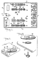
- Fig. 1 shows, in plan view, the interior of a retail store.
- the store has outer walls 10 and an entrance and exit way 12.
- Articles of merchandise 14 are hung on racks 16 inside the store so that they can be examined by store customers 18.
- private rooms such as dressing rooms 20 and rest rooms 22 for the use of store customers. Customers may bring articles of merchandise 14 into these private rooms and try them on so that they can decide whether to purchase them.
- Special security tags 24 are fastened to the articles of merchandise 14. These security tags contain targets which protect the merchandise from theft.
- a store exit monitor 26 is arranged at the exit way 12 of the store; and if an article of merchandise 14 with an attached security tag 24 is carried through the exit way 12 past the monitor 26, the monitor will detect the security tag target and actuate an alarm.
- a customer makes a legitimate purchase, the customer takes the merchandise 14 to a counter 28 where a store clerk 30 removes the security tag 24 using a special tool 32. The customer may then take the merchandise through the exit way 12 without activating the alarm.
- the security tags 24 can be quite securely fastened to the merchandise 14 so as to prevent unauthorized removal and yet can be quickly removed by the store clerk using the special tool 32. Nevertheless, by use of a large tool such as pruning shears or heavy cable cutters, it may be possible, after a time, to destroy the locking mechanism on the security tag and remove it from the merchandise. Any such activity would be readily noticed if it were attempted in the public area of the store. However, if a shoplifter takes the merchandise into one of the dressing rooms 20 or rest rooms 22, the shoplifter is assured of privacy and may work on the fastener of the security tag for as long as necessary to destroy it without being noticed. The shoplifter may then leave the security tag in the private room and take the merchandise out through the exit way 12 without being detected by the monitor 26.
- a large tool such as pruning shears or heavy cable cutters
- dressing room and rest room monitors 34 are provided in each of the dressing rooms 20 and rest rooms 22. These monitors are similar in construction to the store exit monitor 26; however, they respond to a somewhat different electromagnetic disturbance than the store exit monitors. Thus when articles of merchandise 14 having security tags 24 attached to them are taken into a dressing room or rest room in order to try on the merchandise the monitor 34 will not produce an alarm.
- the security tags 24 are of special construction and, when removed from the articles of merchandise 14, they produce a different electromagnetic disturbance that is detected by the dressing room and rest room monitor 34. Accordingly, whenever a security tag is removed from an article of merchandise in one of the dressing rooms 20 or rest rooms 22, the monitor therein will immediately produce an alarm.
- Fig. 2 shows, in schematic and block diagram form, a swept radio frequency store exit monitor 26 located at the exit way 12 of the store. This monitor may have the same construction as described in United States Patent No. 4,321,586.
- a transmitting antenna 36 and a receiving antenna 38 there is provided on opposite sides of the exit way 12 a transmitting antenna 36 and a receiving antenna 38. Any store customer who leaves the store must walk between these two antennas; and the articles of merchandise which the customer carries pass through electromagnetic fields generated in the vicinity of these antennas.
- the transmitting antenna is energized by the output of an amplifier 40 which in turn receives a continuous swept radio frequency signal from a swept frequency oscillator 42.
- the oscillator in turn is driven by a sweep generator 44.
- the sweep generator produces a 220 hertz signal which causes the swept frequency oscillator to vary its output frequency between 1920 and 2,220 kilohertz at a 220 hertz rate.
- This swept radio frequency signal is converted by the transmitting antenna 36 to a swept radio frequency electromagnetic field in the exit way 12.
- the target contained in the security tag 24 comprises a spiral coil 46 and a capacitor 48 connected in a loop to form a resonant electrical circuit.
- the coil and capacitor are tuned so that their resonant frequency is within the frequency sweep range of the transmitter circuit i.e. between 1,920 and 2,220 kilohertz. Consequently twice during each sweep cycle, the transmitted frequency is the same as the resonant frequency of the target circuit.
- the security tag 24 is in the exit way 12 its target circuit is driven into resonance each time the transmitted frequency passes the resonance frequency of the target circuit. This results is a series of distinctive electromagnetic disturbances which are received by the receiving antenna 38 and detected by the receiving circuits connected to that antenna.
- the receiving antenna 38 is connected to input filters and detector 50 which remove the radio frequency components from the received signals.
- the remaining signal components are then passed through signal processing circuits 52 which examine the components for the distinctive characteristics that are produced by a true resonant circuit having the same Q as the target circuits.
- the output of the signal processing circuits 52 is supplied to a pulse generator 54.
- the pulse generator produces a pulse each time the transmitter frequency sweeps past the resonance frequency of a target circuit in the exit way 12.
- the pulse generator output is applied simultaneously to a signal gate 56 and a noise gate 58.
- These gates are opened alternatively by signals from a signal/noise gate generator 60.
- This gate generator in turn is connected to the receiver input circuits 50 and receives the sweep portion of the received signal.
- the gate generator 60 is set to open the signal gate 56 during those portions of the frequency sweep cycle which bracket the resonant frequency of the target circuits and to open the noise gate 58 during the remaining portions of the frequency sweep cycle.
- the outputs of the signal and noise gates 56 and 58 are applied, respectively, to associated low pass filters or accumulators 62 and 64 which accumulate pulses from the pulse generator 54.
- the outputs of the low pass filters 62 and 64 are compared in a comparator 66.
- the voltage comparator 66 supplies a signal to actuate an alarm 68.
- Fig. 4 shows a dressing room 20 fitted out with a dressing room monitor 34.
- the dressing room 20 typically is a small compartment having just enough space for one individual to change clothes.
- the dressing room monitor includes a transmitting antenna 36 ⁇ and a receiving antenna 38 ⁇ mounted in opposite walls 11 of the dressing room.
- the electrical components of the dressing room monitor 34 are essentially the same as those of the store exit monitor 26 and accordingly the same reference numbers primed are used in Fig. 4 to represent components which are counterparts of components in the store exit monitor 26 of Fig. 2.
- the dressing room monitor 34 operates in the same manner as the store exit monitor 36 except that the swept frequency oscillator 42 ⁇ is set to sweep through a range of frequencies that is somewhat lower than the range of frequencies produced by the swept frequency oscillator 42 of the store exit monitor.
- the oscillator 42 ⁇ is swept between 1,820 and 2,120 kilohertz.
- the gate generator 60 ⁇ of the dressing room monitor 34 is set to open the signal gate 56 ⁇ only during the transmission of a narrow range of transmitted frequencies near the center of the sweep range (i.e. 1,970 kilohertz) during each transmitter frequency sweep cycle.
- This narrow range of transmitter frequencies does not include the resonant frequency of the target circuits when their respective target devices are attached to article of merchandise.
- the resonant frequency of its target circuit becomes shifted to that region of the transmitted frequency sweep which occurs while the signal gate 56 ⁇ is opened.
- detected pulses caused by the target circuit pass through the signal gate and activate the alarm 68 ⁇ .
- the security tag 24 and the manner in which the resonant frequency of its target circuit becomes shifted when the tag is detached from an article of merchandise is illustrated in Figs. 5-7.
- the basic construction of the security tag 24 is the same as described in United States Patent No. 4,590,461 and the description in that patent is incorporated herein by reference.
- the target device 24 has a molded plastic casing 70 which is fastened by means of a tack-like fastener element 72 to a sheet shaped portion of the merchandise 14, e.g. the hem or sleeve of a garment.
- the casing 70 is also formed with a lock housing 78 which accommodates a releasable locking mechanism 80.
- the locking mechanism 80 securely grips the shank of the fastener element 72 when it enters the casing 70 from the lower side after passing through the merchandise 14.
- the fastener element 72 is held in place by the locking mechanism, the casing 70 is securely held to the merchandise 14 and, under normal conditions, it cannot be removed from the merchandise.
- a powerful magnetic force is applied with the special tool 32 at the counter 28 (Fig. 1), the lock housing 74 the locking mechanism is released and the fastener element may easily be removed to allow separation of the security tag 24 from the merchandise.
- a copper ring 82 is interposed between the merchandise 14 and the casing 70 of the security tag 24.
- the shank of the fastener element 72 passes through the center of the copper ring 82.
- the copper ring 82 When the copper ring 82 is in the position shown in Figs. 5 and 7 adjacent, or in close proximity, to the coil 46 and the capacitor 48, the copper ring interacts electrically with the coil and capacitor and shifts their resonant frequency upwardly.
- the coil 46 and capacitor 48 by themselves have a resonant frequency of 1,970 kilohertz
- when the copper ring 82 is positioned close to the coil and capacitor their resonant frequency becomes 2,070 kilohertz.
- the amount of frequency shift depends on the dimensions of the ring 82.
- the store exit monitor 26 operates to detect security tags 24 taken through the store exit way 12 whether or not those tags are attached to articles of merchandise.
- the dressing room monitors 34 operate to detect only security tags which are removed from merchandise within the dressing rooms 20 or the rest rooms 22. This permits store patrons to take merchandise with the security tags attached into these rooms to try on the merchandise without causing an alarm to be actuated.
- the timing diagrams of Figs. 8, 9 and 10 illustrate the manner in which the store exit and dressing room monitors 26 and 34 operate to selectively detect attached or removed security tags.
- the center frequency of the store exit swept frequency oscillator 42 is set at the resonant frequency of the target circuit of the attached security tags 24 with the copper ring 82 in place (i.e. 2,070 kilohertz).
- the frequency sweep is from 1,920 to 2,220 kilohertz, which also includes the resonant frequency of the target circuit of the detached security tags 24 with the copper ring 82 removed (i.e. 1,970 kilohertz).
- the timing of the signal gate 56 is set so that the gate is on while the interrogation frequency, i.e. the output of the swept frequency oscillator 42 passes both through 2,070 kilohertz and 1,970 kilohertz.
- the pulses produced when the interrogation frequency sweeps past the resonant frequency of the tag's target circuit will occur while the signal gate is on. These pulses will pass through the voltage comparator 66 and cause an alarm to be actuated.
- the center frequency of the dressing room monitors is set at the resonant frequency of the detached security tag 24, with the copper ring 82 removed (i.e. 1,970 kilohertz).
- the frequency sweep is from 1,820 to 2,120 kilohertz.
- This also includes the resonant frequency of the target circuit of the attached security tags 24 with the copper ring 82 in place (i.e. - 2,070 kilohertz).
- the timing of the signal gate 56 ⁇ is such that this gate is on only while the interrogation frequency, i.e. the output of the swept frequency oscillator 42 ⁇ passes through 1,970 kilohertz.
- the signal gate 56 ⁇ is off and the noise gate 58 ⁇ is on, at the times when the interrogation frequency passes through the resonant frequency of the target circuits of the attached security tags, i. e. 2,070 kilohertz. Consequently when a garment with a security tag attached is brought into a dressing room 20 or a rest room 22 the pulses produced by the tag's resonant circuit will occur only while the signal gate 56 ⁇ is "off” and its noise gate 58 ⁇ is "on”; and the alarm will not be actuated.
- the security tag 24 is removed from the garment while in the dressing room or rest room, the copper ring 82 will fall away from the resonant circuit and the resonant frequency of the circuit will shift downwardly to 1,970 kilohertz. As a result, the pulses generated by the resonant circuit will occur while the signal gate 5 ⁇ is "on” and this will actuate the alarm 68 ⁇ .
- the signal gate 5 ⁇ is "on" and this will actuate the alarm 68 ⁇ .
- the dressing room signal gates 56 ⁇ may be set to be “on” when the sweep frequency is at 1,970 kilohertz and "off” when the sweep frequency is at 2,070 kilohertz and the dressing room noise gate 58 ⁇ may be set to be “on” when the sweep frequency is at 2,070 kilohertz and "off” when the sweep frequency is at 1,920 kilohertz, thus permitting the store exit and dressing room monitors to have the same sweep frequency.
- Fig. 11 shows an alternative arrangement for controlling the resonant frequency of the target circuit so that it shifts to a lower frequency when the security tag is detached from the merchandise.
- a security tag 24 ⁇ is shown which is similar in construction to the security tag 24 of Fig. 7.
- the basic construction of the security tag 24 ⁇ is the same as shown U.S. Patent No. 4,187,509.
- the outer configuration of the security tag 24 ⁇ is somewhat modified from that of the security tag 24.
- the security tag 24 ⁇ has all the same basic elements of the security tag 24 and those elements which have counterparts in Fig. 7 are given the same reference numerals with a prime.
- the fastener 72 ⁇ is provided with an enlarged molded plastic head 86 in which the copper ring 82 ⁇ is cemented.
- the copper ring 82 ⁇ is held in proper positional relationship to the coil 46 ⁇ and capacitor 48 ⁇ of the target resonant circuit to shift its frequency upward. If the locking mechanism 80 ⁇ or the fastener 72 ⁇ are destroyed so as to remove the fastener from the wafer housing 70 ⁇ , the copper ring 82 ⁇ will become separated from the resonant circuit and the resonant frequency of the circuit will decrease. Thus, the removed target will be detected in the same manner as in the embodiment of Figs. 5-7.
- the present invention provides a novel electronic article surveillance system and security tag construction which enables the detection of unauthorized removal of security tags from articles of merchandise in dressing rooms and rest rooms without otherwise affecting the privacy of persons using those rooms.
Landscapes
- Physics & Mathematics (AREA)
- Engineering & Computer Science (AREA)
- Automation & Control Theory (AREA)
- Computer Security & Cryptography (AREA)
- Electromagnetism (AREA)
- General Physics & Mathematics (AREA)
- Signal Processing (AREA)
- Burglar Alarm Systems (AREA)
Claims (29)
- Elektronisches Artikelüberwachungs-System zum Schutz von Ware (14) vor Diebstahl aus einem Laden, der eine Kabine (20, 22) hat, die sich innerhalb eines geschützten Bereichs des Ladens befindet, welches System umfaßt:
eine erste Überwachungseinrichtung (26), die angeordnet ist, um auf eine erste charakteristische elektromagnetische Störung in einem Ausgangsweg (12) aus dem geschützten Bereich des Ladens anzusprechen,
eine zweite Überwachungseinrichtung (34), die auf eine zweite charakteristische elektromagnetische Störung innerhalb der Kabine (20, 22) anspricht, um einen Alarm zu erzeugen,
ein Sicherheits-Schildchen (24, 24'), das so konstruiert ist, daß es an einem Artikel der Ware (14) befestigt werden kann, wobei das Sicherheits-Schildchen von dem Artikel der Ware (14) nur mittels eines speziellen Werkzeugs (32) entfernbar ist,
wobei das Sicherheits-Schildchen (24, 24') so aufgebaut ist, daß es eine erste charakteristische elektromagnetische Störung erzeugt, wenn es an dem Artikel der Ware (14) befestigt ist, und eine zweite charakteristische elektromagnetische Störung erzeugt, wenn es von dem Artikel der Ware entfernt ist,
dadurch gekennzeichnet,
daß das Sicherheits-Schildchen (24, 24') ein leitendes Element (82, 82' enthält, das wenn es angrenzend an einen Ziel- oder Meßkreis positioniert ist, die Resonanzfrequenz des Meßkreises verändert, so daß dieser die erste charakteristische elektromagnetische Störung erzeugt,
und
daß das leitende Element (82, 82') in einer Position angrenzend an den Meßkreis (46, 48) gehalten wird, wenn das Sicherheits-Schildchen (24, 24') an einem Artikel der Ware (14) befestigt ist, und von dem Sicherheits-Schildchen (24, 24') freigegeben wird, wenn das Sicherheits-Schildchen von dem Artikel der Ware getrennt (14) wird. - Elektronisches Artikelüberwachungs-System nach Anspruch 1, dadurch gekennzeichnet, daß das Sicherheits-Schildchen (24, 24') einen Ziel- oder Meßkreis (46, 48) enthält, der die ersten und zweiten charakteristischen elektromagnetischen Störungen in Reaktion auf Abfragesignale erzeugt, und daß die ersten und zweiten Überwachungseinrichtungen (26, 34) jeweils Mittel zum Erzeugen der Abfragesignale enthalten.
- Elektronisches Artikelüberwachungs-System nach Anspruch 2, dadurch gekennzeichnet, daß der Meßkreis (46, 48) ein Resonanzkreis ist und daß das SicherheitsSchildchen (24, 24') eine erste Resonanzfrequenz hat, wenn das Sicherheits-Schildchen (24, 24') an einem Artikel der Ware (14) befestigt ist, und eine zweite Resonanzfrequenz hat, wenn das Sicherheits-Schildchen (24, 24') von dem Artikel der Ware (14) entfernt ist.
- Elektronisches Artikelüberwachungs-System nach Anspruch 3, dadurch gekennzeichnet, daß die ersten und zweiten Überwachungseinrichtungen (26, 34) WobbelfrequenzAbfragesignale erzeugen, die wiederholt durch einen Frequenzbereich gewobbelt werden, der die erste und die zweite Resonanzfrequenz enthält, wobei die erste Überwachungseinrichtung (26) auf elektromagnetische Störungen anspricht, die durch einen Resonanzkreis erzeugt werden, der sich bei der ersten Resonanzfrequenz in Resonanz befindet, und die zweite Überwachungseinrichtung (34) nur auf elektromagnetische Störungen anspricht, die durch einen Resonanzkreis erzeugt werden, der sich bei der zweiten Resonanzfrequenz in Resonanz befindet.
- Elektronisches Artikelüberwachungs-System nach Anspruch 4, dadurch gekennzeichnet, daß die ersten und zweiten Überwachungseinrichtungen (26, 34) jeweils erste und zweite Signaltore (56, 56') enthalten, durch die Signale, die auf die Erfassung der ersten und zweiten elektromagnetischen Störungen hin erzeugt sind, geleitet werden müssen, um einen Alarm (68, 68') auszulösen, und ferner dadurch gekennzeichnet, daß die erste Überwachungseinrichtung (26) des weiteren ein erstes Signaltor-Betätigungsmittel (60) zum Veranlassen des ersten Signaltors (56) enthält, Signale durchzulassen, die während Zeitintervallen auftreten, in denen deren Abfragesignal durch die erste Resonanzfrequenz gewobbelt wird, und daß die zweite Überwachungseinrichtung (34) des weiteren ein zweites Signaltor-Betätigungsmittel (60) zum Veranlassen des zweiten Signaltors (56') enthält, Signale durchzulassen, die während Zeitintervallen auftreten, in denen deren Abfragesignal durch die zweite Resonanzfreauenz gewobbelt wird.
- Elektronisches Artikelüberwachungs-System nach Anspruch 5, dadurch gekennzeichnet, daß das erste Signaltor-Betätigungsmittel (60) außerdem das erste Signaltor (56) veranlaßt, Signale durchzulassen, die während derjenigen Zeitintervalle auftreten, in denen deren Abfragesignal durch die zweite Resonanzfrequenz gewobbelt wird.
- Elektronisches Artikelüberwachungs-System nach Anspruch 6, dadurch gekennzeichnet, daß das Sicherheits-Schildchen (24, 24') ein Gehäuse (70, 70'), welches den Meßkreis (46, 48) enthält, und eine stiftähnliche Befestigungsvorrichtung (72, 72') umfaßt, die einen Schaft hat, der durch einen Artikel der Ware (14) vorsteht und auf der Innenseite des Gehäuses durch einen Verriegelungsmechanismus (80, 80') darin gehalten wird.
- Elektronisches Artikelüberwachungs-System nach Anspruch 7, dadurch gekennzeichnet, daß das Element (82, 82') in Form eines Rings ausgebildet ist und an seinem Ort zwischen dem Artikel der Ware (14) und dem Gehäuse (70, 70') gehalten wird, wobei der Schaft des Befestigungsteils durch den Ring verläuft.
- Elektronisches Artikelüberwachungs-System nach Anspruch 7 oder 8, dadurch gekennzeichnet, daß das Element (82, 82') in Form eines Rings ausgebildet ist und in den Kopf des stiftähnlichen Befestigungsteils (72, 72') eingebettet ist.
- Elektronisches Artikelüberwachungs-System nach einem der Ansprüche 1 bis 9, dadurch gekennzeichnet, daß der Meßkreis (46, 48) eine elektrische Resonanzschaltung ist, deren Frequenz durch das Element (82, 82') verschoben wird, wenn das Element angrenzend an den Meßkreis (46, 48) positioniert wird.
- Elektronisches Artikelüberwachungs-System nach einem der Ansprüche 1 und 7 bis 10, dadurch gekennzeichnet, daß das Sicherheits-Schildchen (24, 24') einen Meßkreis (46, 48) enthält, der die ersten und zweiten charakteristischen elektromagnetischen Störungen in Reaktion auf Abfragesignale erzeugt, und daß die ersten und zweiten Überwachungseinrichtungen (26, 34) jeweils Mittel (40, 42, 44, 40', 42' 44') zum Erzeugen der Abfragesignale enthalten.
- Elektronisches Artikelüberwachungs-System nach Anspruch 11, dadurch gekennzeichnet, daß der Meßkreis (46, 48) eine Resonanzschaltung ist und daß das Sicherheits-Schildchen (24, 24') derart aufgebaut ist, daß der Meßkreis (46, 48) eine erste Resonanzfrequenz hat, wenn das Sicherheits-Schildchen (24, 24') an einem Artikel der Ware (14) befestigt ist, und eine zweite Resonanzfrequenz hat, wenn das Sicherheits-Schildchen (24, 24') von dem Artikel der Ware (14) entfernt ist.
- Elektronisches Artikelüberwachungs-System nach einem der Ansprüche 10 bis 12, dadurch gekennzeichnet, daß die ersten und zweiten Überwachungseinrichtungen (26, 34) Wobbelfrequenz-Abfragesignale erzeugen, die durch einen Frequenzbereich gewobbelt werden, der die erste und die zweite Resonanzfrequenz enthält, wobei die erste Überwachungseinrichtung (26) auf elektromagnetische Störungen anspricht, die durch einen Resonanzkreis erzeugt werden, der sich bei der ersten Resonanzfrequenz in Resonanz befindet, und wobei die zweite Überwachungseinrichtung (34) nur auf elektromagnetische Störungen anspricht, die durch einen Resonanzkreis erzeugt werden, der sich bei der zweiten Resonanzfrequenz in Resonanz befindet.
- Elektronisches Artikelüberwachungs-System nach Anspruch 13, dadurch gekennzeichnet, daß die erste Überwachungseinrichtung (26) auch auf elektromagnetische Störungen anspricht, die durch einen Resonanzkreis erzeugt werden, der sich bei der zweiten Resonanzfrequenz in Resonanz befindet.
- Elektronisches Artikelüberwachungs-System nach Anspruch 13 oder 14, dadurch gekennzeichnet, daß die ersten und zweiten Überwachungseinrichtungen (26, 34) jeweils erste und zweite Signaltore (56, 56') enthalten, durch die Signale, welche auf die Erfassung der ersten und zweiten elektromagnetischen Störungen hin erzeugt sind, geleitet werden müssen, um einen Alarm (68, 68') auszulösen, daß die erste Überwachungseinrichtung (26) des weiteren ein erstes Signaltor-Betätigungsmittel (60) zum Veranlassen des ersten Signaltors enthält, Signale durchzulassen, die während derjenigen Zeitintervalle auftreten, in denen deren Abfragesignal durch die erste Resonanzfrequenz gewobbelt wird, und daß die zweite Überwachungseinrichtung (34) des weiteren ein zweites Signaltor-Betätigungsmittel (60) zum Veranlassen des zweiten Signaltore (56') enthält, Signale durchzulassen, die während derjenigen Zeitintervalle auftreten, in denen deren Abfragesignal durch die zweite Resonanzfrequenz gewobbelt wird.
- Elektronisches Artikelüberwachungs-System nach Anspruch 15, dadurch gekennzeichnet, daß das erste Signaltor-Betätigungsmittel (60) außerdem das erste Signaltore (56) veranlaßt, Signale durchzulassen, die während derjenigen Zeitintervalle auftreten, in denen deren Abfragesignal durch die zweite Resonanzfrequenz gewobbelt wird.
- Sicherheits-Schildchen (24, 24') zur Benutzung in einem elektronischen Überwachungs-System, welches Schildchen umfaßt:
ein Gehäuse (70, 70'),
eine Befestigungsvorrichtung (78, 78') zum Befestigen des Gehäuses an einem Artikel der Ware (14), wobei die Befestigungsvorrichtung (78, 78') nur durch ein spezielles Werkzeug (32)lösbar ist, um ein Trennen des Gehäuses (70, 70') von dem Artikel der Ware (14) zu gestatten,
einen Ziel- oder Meßkreis (46, 48), der in dem Gehäuse (70, 70') montiert ist, wobei der Meßkreis (46, 48) derart beschaffen ist, daß er eine erste charakteristische elektromagnetische Störung erzeugt, wenn die Befestigungsvorrichtung (78, 78') das Gehäuse (70, 70') an dem Artikel der Ware (14) befestigt, und eine zweite charakteristische elektromagnetische Störung erzeugt, wenn das Gehäuse (70, 70') von dem Artikel der Ware (14) getrennt ist,
dadurch gekennzeichnet,
daß das Sicherheit-Schildchen (24, 24') ein leitendes Element(82, 82') enthält, das wenn es angrenzend an den Meßkreis (46,48) positioniert ist, die Resonanzfrequenz des Meßkreises verändert, so daß es die ersten charakteristischen elektromagnetischen Störungen erzeugt, und
daß das leitende Element (82, 82') in Position angrenzend an das Ziel (46, 48) gehalten wird, wenn die Befestigungsvorrichtung (78, 78') das Gehäuse (70, 70') an einem Artikel der Ware (14) hält, sich jedoch von dem Meßkreis (46, 48) trennt, wenn das Gehäuse (70, 70') von dem Artikel der Ware (14) getrennt wird. - Sicherheits-Schildchen nach Anspruch 17, dadurch gekennzeichnet, daß der Meßkreis (46, 48) derart beschaffen ist, daß er die ersten und zweiten charakteristischen elektromagnetischen Störungen bei einer ersten bzw. einer zweiten Frequenzen erzeugt.
- Sicherheits-Schildchen (24, 24') nach Anspruch 17, dadurch gekennzeichnet, daß der Meßkreis (46, 48) derart beschaffen ist, daß er die ersten und zweiten elektromagnetischen Störungen in Reaktion auf Abfragesignale erzeugt.
- Sicherheits-Schildchen (24, 24') nach Anspruch 17 bis 19, dadurch gekennzeichnet, daß das Element (82, 82') durch einen Befestigungsteil (72, 72') gegen das Gehäuse gehalten wird.
- Sicherheits-Schildchen (24, 24') nach Anspruch 20, dadurch gekennzeichnet, daß der Befestigungsteil (72, 72') ein stiftähnliches Bauteil ist, das einen Schaft hat, der durch einen Artikel der Ware (14) verläuft und innerhalb des Gehäuses durch einen Verriegelungsaufbau (80, 80') gehalten wird.
- Sicherheits-Schildchen (24, 24') nach Anspruch 21, dadurch gekennzeichnet, daß das Element (82, 82') in Form eines Rings ausgebildet ist und daß der Schaft des Befestigungsteils (72, 72') durch das Zentrum des Rings verläuft.
- Sicherheits-Schildchen (24') nach einem der Ansprüche 20 bis 22, dadurch gekennzeichnet, daß das Element (82') in dem Kopf des Befestigungsteils (72') befestigt ist.
- Sicherheits-Schildchen (24, 24') nach einem der Ansprüche 17 bis 23, dadurch gekennzeichnet, daß der Meßkreis (46, 48) eine elektrische Resonanzschaltung ist.
- Sicherheits-Schildchen (24, 24') nach Anspruch 24, dadurch gekennzeichnet, daß der Meßkreis (46, 48) derart beschaffen ist, daß er eine erste Resonanzfrequenz hat, wenn der Befestigungsteil (72, 72') das Gehäuse (70, 70') an dem Artikel der Ware (14) befestigt, und eine zweite Resonanzfrequenz hat, wenn das Gehäuse (70, 70') von der Ware (14) getrennt ist.
- Sicherheits-Schildchen (24, 24') nach Anspruch 25, dadurch gekennzeichnet, daß das Sicherheits-Schildchen ein Element (82, 82') enthält, dessen elektrischen Eigenschaften derart sind, daß wenn das Element (82, 82') angrenzend an das Gehäuse positioniert wird, es die Resonanzfrequenz des Meßkreises (46, 48) von der zweiten Resonanzfrequenz in die erste Resonanzfrequenz ändert.
- Sicherheits-Schildchen (24, 24') nach Anspruch 26, dadurch gekennzeichnet, daß das Element (82, 82') angrenzend an das Gehäuse (70, 70') gehalten wird, wenn der Befestigungsteil (72, 72') das Gehäuse (70, 70') gegen den Artikel der Ware (14) hält.
- Sicherheits-Schildchen (24, 24') nach Anspruch 26 oder 27, dadurch gekennzeichnet, daß das Element (82, 82') ein elektrisch leitender Ring ist.
- Sicherheits-Schildchen (24, 24') nach Anspruch 28, dadurch gekennzeichnet, daß der Befestigungsteil (72, 72') ein stiftähnliches Bauteil ist, das einen Schaft hat, der durch den Artikel der Ware (14) und den Ring (82, 82') und in einen Verriegelungsmechanismus (80, 80') in dem Gehäuse (72, 72') hinein verläuft.
Applications Claiming Priority (2)
| Application Number | Priority Date | Filing Date | Title |
|---|---|---|---|
| US13120 | 1987-02-10 | ||
| US07/013,120 US4751500A (en) | 1987-02-10 | 1987-02-10 | Detection of unauthorized removal of theft detection target devices |
Publications (3)
| Publication Number | Publication Date |
|---|---|
| EP0278492A2 EP0278492A2 (de) | 1988-08-17 |
| EP0278492A3 EP0278492A3 (en) | 1989-03-08 |
| EP0278492B1 true EP0278492B1 (de) | 1992-12-02 |
Family
ID=21758409
Family Applications (1)
| Application Number | Title | Priority Date | Filing Date |
|---|---|---|---|
| EP88101955A Expired - Lifetime EP0278492B1 (de) | 1987-02-10 | 1988-02-10 | Erfassung nichterlaubter Wegnahme von Vorrichtungen mit Diebstahlsicherungsmarke |
Country Status (8)
| Country | Link |
|---|---|
| US (1) | US4751500A (de) |
| EP (1) | EP0278492B1 (de) |
| JP (1) | JPS63200298A (de) |
| AU (1) | AU605832B2 (de) |
| BR (1) | BR8800447A (de) |
| DE (2) | DE3876257T2 (de) |
| DK (1) | DK65288A (de) |
| ZA (1) | ZA88180B (de) |
Families Citing this family (36)
| Publication number | Priority date | Publication date | Assignee | Title |
|---|---|---|---|---|
| NL8800367A (nl) * | 1988-02-15 | 1989-09-01 | Id Systems Int | Diefstalbeveiligingslabel. |
| ATE109292T1 (de) * | 1988-05-27 | 1994-08-15 | Digital Products Corp | Belegschafts-sicherheitsüberwachungsvorrichtung |
| NL8900461A (nl) * | 1989-02-24 | 1990-09-17 | Nedap Nv | Wafer met bevestigingsbeugel. |
| US5019801A (en) * | 1989-07-24 | 1991-05-28 | Identitech | Article surveillance system having target removal sensor |
| GB8928966D0 (en) * | 1989-12-21 | 1990-02-28 | Scient Generics Ltd | Security tag attachment |
| US5808285A (en) | 1990-09-17 | 1998-09-15 | Metrologic Instruments, Inc. | Portable code symbol reading device with one-way wireless data packet transmission link to base unit employing condition-dependent acoustical signalling for data packet reception acknowledgement |
| US7077327B1 (en) * | 1990-09-17 | 2006-07-18 | Metrologic Instruments, Inc. | System for reading bar code symbols using bar code readers having RF signal transmission links with base stations |
| FR2671212B1 (fr) * | 1990-12-28 | 1993-06-11 | Lecuyer Herve | Dispositif de protection d'objets, notamment des objets d'art. |
| US6460769B1 (en) * | 1991-09-17 | 2002-10-08 | Metrologic Instruments, Inc. | System for reading bar code symbols using portable bar code symbol readers having one-way RF signal transmission links with base stations |
| US6761317B1 (en) | 1991-09-17 | 2004-07-13 | Metrologic Instruments, Inc. | Reading bar code symbols using readers having one-way RF signal transmission links with base stations |
| US5237307A (en) * | 1991-11-27 | 1993-08-17 | The United States Of America As Represented By The United States Department Of Energy | Non-contact tamper sensing by electronic means |
| ES2086137T3 (es) * | 1991-12-19 | 1996-06-16 | Ake Gustafson | Dispositivo de precinto de seguridad. |
| US5206626A (en) * | 1991-12-24 | 1993-04-27 | Knogo Corporation | Stabilized article surveillance responder |
| DE4323883C2 (de) * | 1993-07-16 | 2002-11-07 | Meto International Gmbh | Diebstahlsicherungsetikett |
| SE504899C2 (sv) * | 1994-05-16 | 1997-05-26 | Leif Aasbrink | Anordning för att förhindra störningar i elektroniska larmsystem |
| US8261993B2 (en) | 1994-05-25 | 2012-09-11 | Marshall Feature Recognition, Llc | Method and apparatus for accessing electronic data via a familiar printed medium |
| US7712668B2 (en) | 1994-05-25 | 2010-05-11 | Marshall Feature Recognition, Llc | Method and apparatus for accessing electronic data via a familiar printed medium |
| US8910876B2 (en) | 1994-05-25 | 2014-12-16 | Marshall Feature Recognition, Llc | Method and apparatus for accessing electronic data via a familiar printed medium |
| US6866196B1 (en) | 1994-05-25 | 2005-03-15 | Spencer A. Rathus | Method and apparatus for accessing electronic data via a familiar printed medium |
| US6025781A (en) * | 1997-02-03 | 2000-02-15 | Avery Dennison Corporation | Device for use in detecting the unauthorized removal of an article of commerce from a store or other business establishment and method of making the same |
| US5949336A (en) * | 1997-02-03 | 1999-09-07 | Avery Dennison Corporation | Fastener assembly and method of making the same |
| DE19738309A1 (de) * | 1997-09-02 | 1999-03-04 | Meto International Gmbh | Vorrichtung zur Sicherung von Artikeln gegen Diebstahl, entsprechendes Herstellungsverfahren und Vorrichtung zur Durchführung des Verfahrens |
| US5990791A (en) * | 1997-10-22 | 1999-11-23 | William B. Spargur | Anti-theft detection system |
| US6255950B1 (en) * | 1999-10-19 | 2001-07-03 | Sensormatic Electronics Corporation | Tack assembly for electronic article surveillance tags |
| US6449991B1 (en) | 2000-04-12 | 2002-09-17 | Sensormatic Electronics Corporation | One part theft deterrent device |
| BR0107379A (pt) | 2000-10-26 | 2002-09-24 | Alpha Security Prod Inc | Retentor de etiquetas eas usado para conectar uma etiqueta eas com um artigo de mercadoria para desencorajar o furto em lojas, e, processo para destravar o mesmo |
| US20030040925A1 (en) * | 2001-08-22 | 2003-02-27 | Koninklijke Philips Electronics N.V. | Vision-based method and apparatus for detecting fraudulent events in a retail environment |
| EP1497802A4 (de) * | 2002-04-08 | 2008-07-30 | Adel Odeh Sayegh | Artikelsicherungsetikett mit einem metallclip |
| US7652574B2 (en) * | 2002-04-08 | 2010-01-26 | Sayegh Adel O | Article surveillance tag having a vial |
| US7123146B1 (en) * | 2004-09-23 | 2006-10-17 | Ncr Corporation | Security method for theft prone areas of a retail store |
| DE202008005180U1 (de) * | 2008-04-14 | 2008-06-26 | Heico Befestigungstechnik Gmbh | Sicherungsnagel |
| US9298954B1 (en) | 2010-02-03 | 2016-03-29 | Synapse Wireless, Inc. | Tag security systems and methods for articles of merchandise |
| US9092963B2 (en) * | 2010-03-29 | 2015-07-28 | Qualcomm Incorporated | Wireless tracking device |
| US9324015B2 (en) * | 2012-05-22 | 2016-04-26 | Checkpoint Systems, Inc. | Solid housing tag |
| ITMI20121096A1 (it) * | 2012-06-22 | 2013-12-23 | Roberto Laferla | Dispositivo anti-taccheggio, particolarmente per articoli di negozi e simili. |
| CN105065887A (zh) * | 2015-08-11 | 2015-11-18 | 李娜 | 一种安装结构及设备 |
Family Cites Families (17)
| Publication number | Priority date | Publication date | Assignee | Title |
|---|---|---|---|---|
| US2474271A (en) * | 1945-05-31 | 1949-06-28 | Harold F Meyer | Method for protection of objects |
| US2774060A (en) * | 1953-06-15 | 1956-12-11 | Richard B Thompson | Detecting means for stolen goods |
| US3747086A (en) * | 1968-03-22 | 1973-07-17 | Shoplifter International Inc | Deactivatable ferromagnetic marker for detection of objects having marker secured thereto and method and system of using same |
| US3493955A (en) * | 1968-04-17 | 1970-02-03 | Monere Corp | Method and apparatus for detecting the unauthorized movement of articles |
| US3713133A (en) * | 1971-02-16 | 1973-01-23 | R Nathans | Rf and sonic systems for preventing shoplifting of goods and unauthorized removal of capsules affixed thereto for protecting goods |
| US3810147A (en) * | 1971-12-30 | 1974-05-07 | G Lichtblau | Electronic security system |
| US3858280A (en) * | 1972-11-17 | 1975-01-07 | I D Engineering Inc | Fastening clip |
| US3820104A (en) * | 1972-12-15 | 1974-06-25 | Stop Loss Inc | Method and system for detecting an object within a magnetic field interrogation zone |
| US3820103A (en) * | 1972-12-15 | 1974-06-25 | Stop Loss Inc | System for detecting an object within a magnetic field |
| US3911534A (en) * | 1974-10-30 | 1975-10-14 | I D Engineering Inc | Anti-theft fastening device |
| DE2539043A1 (de) * | 1974-11-15 | 1977-03-10 | Jank Wilhelm | Resonator mit ferritkern zur einrichtung zur ermittlung unbefugt mitgefuehrter gegenstaende |
| US4321586A (en) * | 1980-08-21 | 1982-03-23 | Knogo Corporation | Article theft detection |
| US4623877A (en) * | 1983-06-30 | 1986-11-18 | Knogo Corporation | Method and apparatus for detection of targets in an interrogation zone |
| US4531264A (en) * | 1983-07-27 | 1985-07-30 | Knogo Corporation | Theft detection system target fastener |
| US4642613A (en) * | 1984-03-16 | 1987-02-10 | Knogo Corporation | Electronic theft detection apparatus with responder elements on protected articles |
| US4590461A (en) * | 1984-10-05 | 1986-05-20 | Knogo Corporation | Tamper resistant target wafer and fastener assembly |
| NL8501721A (nl) * | 1985-06-14 | 1987-01-02 | Nedap Nv | Detectiestelsel. |
-
1987
- 1987-02-10 US US07/013,120 patent/US4751500A/en not_active Expired - Fee Related
-
1988
- 1988-01-12 ZA ZA88180A patent/ZA88180B/xx unknown
- 1988-02-04 BR BR8800447A patent/BR8800447A/pt not_active Application Discontinuation
- 1988-02-09 DK DK065288A patent/DK65288A/da not_active Application Discontinuation
- 1988-02-09 AU AU11465/88A patent/AU605832B2/en not_active Ceased
- 1988-02-10 DE DE8888101955T patent/DE3876257T2/de not_active Expired - Fee Related
- 1988-02-10 JP JP63027863A patent/JPS63200298A/ja active Granted
- 1988-02-10 EP EP88101955A patent/EP0278492B1/de not_active Expired - Lifetime
- 1988-02-10 DE DE198888101955T patent/DE278492T1/de active Pending
Also Published As
| Publication number | Publication date |
|---|---|
| JPS63200298A (ja) | 1988-08-18 |
| EP0278492A2 (de) | 1988-08-17 |
| DK65288A (da) | 1988-08-11 |
| JPH0586597B2 (de) | 1993-12-13 |
| EP0278492A3 (en) | 1989-03-08 |
| ZA88180B (en) | 1988-11-30 |
| DE278492T1 (de) | 1990-10-18 |
| BR8800447A (pt) | 1988-09-20 |
| AU1146588A (en) | 1988-08-11 |
| DK65288D0 (da) | 1988-02-09 |
| AU605832B2 (en) | 1991-01-24 |
| US4751500A (en) | 1988-06-14 |
| DE3876257D1 (de) | 1993-01-14 |
| DE3876257T2 (de) | 1993-06-24 |
Similar Documents
| Publication | Publication Date | Title |
|---|---|---|
| EP0278492B1 (de) | Erfassung nichterlaubter Wegnahme von Vorrichtungen mit Diebstahlsicherungsmarke | |
| CA1111123A (en) | Electronic theft detection system for monitoring wide passageways | |
| US3713133A (en) | Rf and sonic systems for preventing shoplifting of goods and unauthorized removal of capsules affixed thereto for protecting goods | |
| US5245317A (en) | Article theft detection apparatus | |
| US4962369A (en) | Merchandise security system utilizing RF transmitter | |
| US8421628B2 (en) | Asset protection system | |
| US4812811A (en) | Alarm tag | |
| US3711848A (en) | Method of and apparatus for the detection of stolen articles | |
| US9165446B2 (en) | Anti-theft security device and perimeter detection system | |
| US5825291A (en) | Electronic article surveillance system | |
| CA1240772A (en) | Electronic surveillance system employing the doppler effect | |
| US6512457B2 (en) | Monitoring device adapted for use with an electronic article surveillance system | |
| US8451128B2 (en) | Asset protection system | |
| US3609741A (en) | Prevention of unauthorized movement of articles between predetermined areas | |
| AU2010242839A1 (en) | Transmit-only electronic article surveillance system and method | |
| US20140043163A1 (en) | Asset protection system | |
| US6573835B2 (en) | Child monitoring device | |
| EP0157095B1 (de) | Elektronische Diebstahl-Warneinrichtung | |
| EP0736850B1 (de) | Verfahren zum Verhindern von Ladendiebstahl und elektronisches Diebstahl-Detektierungssystem | |
| AU769526B2 (en) | Security systems for inhibiting theft of goods from retail stores | |
| US4060040A (en) | Antitheft system for sales areas | |
| JPH09267858A (ja) | 盗難監視装置および警報タグ解除装置 | |
| NL8304413A (nl) | Universele alarmwafer. | |
| CA2347333A1 (en) | Electromagnetic anti-shoplifting system | |
| US20070046437A1 (en) | Electronic Transmission Device for Activation of Electronic Article Surveillance Systems |
Legal Events
| Date | Code | Title | Description |
|---|---|---|---|
| PUAI | Public reference made under article 153(3) epc to a published international application that has entered the european phase |
Free format text: ORIGINAL CODE: 0009012 |
|
| AK | Designated contracting states |
Kind code of ref document: A2 Designated state(s): BE DE FR GB IT NL SE |
|
| PUAL | Search report despatched |
Free format text: ORIGINAL CODE: 0009013 |
|
| AK | Designated contracting states |
Kind code of ref document: A3 Designated state(s): BE DE FR GB IT NL SE |
|
| 17P | Request for examination filed |
Effective date: 19890606 |
|
| 17Q | First examination report despatched |
Effective date: 19891019 |
|
| ITCL | It: translation for ep claims filed |
Representative=s name: ZINI MARANESI |
|
| TCNL | Nl: translation of patent claims filed | ||
| EL | Fr: translation of claims filed | ||
| DET | De: translation of patent claims | ||
| GRAA | (expected) grant |
Free format text: ORIGINAL CODE: 0009210 |
|
| AK | Designated contracting states |
Kind code of ref document: B1 Designated state(s): BE DE FR GB IT NL SE |
|
| REF | Corresponds to: |
Ref document number: 3876257 Country of ref document: DE Date of ref document: 19930114 |
|
| ITF | It: translation for a ep patent filed |
Owner name: JACOBACCI CASETTA & PERANI S.P.A. |
|
| ET | Fr: translation filed | ||
| K2C2 | Correction of patent specification (partial reprint) published |
Effective date: 19921202 |
|
| PLBE | No opposition filed within time limit |
Free format text: ORIGINAL CODE: 0009261 |
|
| STAA | Information on the status of an ep patent application or granted ep patent |
Free format text: STATUS: NO OPPOSITION FILED WITHIN TIME LIMIT |
|
| 26N | No opposition filed | ||
| EAL | Se: european patent in force in sweden |
Ref document number: 88101955.8 |
|
| PGFP | Annual fee paid to national office [announced via postgrant information from national office to epo] |
Ref country code: NL Payment date: 19950228 Year of fee payment: 8 |
|
| PGFP | Annual fee paid to national office [announced via postgrant information from national office to epo] |
Ref country code: BE Payment date: 19950330 Year of fee payment: 8 |
|
| PG25 | Lapsed in a contracting state [announced via postgrant information from national office to epo] |
Ref country code: BE Effective date: 19960228 |
|
| BERE | Be: lapsed |
Owner name: KNOGO CORP. Effective date: 19960228 |
|
| PG25 | Lapsed in a contracting state [announced via postgrant information from national office to epo] |
Ref country code: NL Effective date: 19960901 |
|
| NLV4 | Nl: lapsed or anulled due to non-payment of the annual fee |
Effective date: 19960901 |
|
| PGFP | Annual fee paid to national office [announced via postgrant information from national office to epo] |
Ref country code: SE Payment date: 19980218 Year of fee payment: 11 |
|
| PG25 | Lapsed in a contracting state [announced via postgrant information from national office to epo] |
Ref country code: SE Free format text: LAPSE BECAUSE OF NON-PAYMENT OF DUE FEES Effective date: 19990211 |
|
| EUG | Se: european patent has lapsed |
Ref document number: 88101955.8 |
|
| PGFP | Annual fee paid to national office [announced via postgrant information from national office to epo] |
Ref country code: DE Payment date: 20010205 Year of fee payment: 14 |
|
| PGFP | Annual fee paid to national office [announced via postgrant information from national office to epo] |
Ref country code: GB Payment date: 20010207 Year of fee payment: 14 |
|
| PGFP | Annual fee paid to national office [announced via postgrant information from national office to epo] |
Ref country code: FR Payment date: 20010213 Year of fee payment: 14 |
|
| REG | Reference to a national code |
Ref country code: GB Ref legal event code: IF02 |
|
| PG25 | Lapsed in a contracting state [announced via postgrant information from national office to epo] |
Ref country code: GB Free format text: LAPSE BECAUSE OF NON-PAYMENT OF DUE FEES Effective date: 20020210 |
|
| PG25 | Lapsed in a contracting state [announced via postgrant information from national office to epo] |
Ref country code: DE Free format text: LAPSE BECAUSE OF NON-PAYMENT OF DUE FEES Effective date: 20020903 |
|
| GBPC | Gb: european patent ceased through non-payment of renewal fee |
Effective date: 20020210 |
|
| PG25 | Lapsed in a contracting state [announced via postgrant information from national office to epo] |
Ref country code: FR Free format text: LAPSE BECAUSE OF NON-PAYMENT OF DUE FEES Effective date: 20021031 |
|
| REG | Reference to a national code |
Ref country code: FR Ref legal event code: ST |
|
| PG25 | Lapsed in a contracting state [announced via postgrant information from national office to epo] |
Ref country code: IT Free format text: LAPSE BECAUSE OF NON-PAYMENT OF DUE FEES;WARNING: LAPSES OF ITALIAN PATENTS WITH EFFECTIVE DATE BEFORE 2007 MAY HAVE OCCURRED AT ANY TIME BEFORE 2007. THE CORRECT EFFECTIVE DATE MAY BE DIFFERENT FROM THE ONE RECORDED. Effective date: 20050210 |