EP0278021B1 - Jauges de contrainte à résistance avec une couche mince métallique discontinue - Google Patents
Jauges de contrainte à résistance avec une couche mince métallique discontinue Download PDFInfo
- Publication number
- EP0278021B1 EP0278021B1 EP87101733A EP87101733A EP0278021B1 EP 0278021 B1 EP0278021 B1 EP 0278021B1 EP 87101733 A EP87101733 A EP 87101733A EP 87101733 A EP87101733 A EP 87101733A EP 0278021 B1 EP0278021 B1 EP 0278021B1
- Authority
- EP
- European Patent Office
- Prior art keywords
- substrate
- metal layer
- strain gauges
- discontinuous metal
- resistance
- Prior art date
- Legal status (The legal status is an assumption and is not a legal conclusion. Google has not performed a legal analysis and makes no representation as to the accuracy of the status listed.)
- Expired - Lifetime
Links
- 229910052751 metal Inorganic materials 0.000 claims description 37
- 239000002184 metal Substances 0.000 claims description 37
- 239000000758 substrate Substances 0.000 claims description 22
- 238000009792 diffusion process Methods 0.000 claims description 8
- ATJFFYVFTNAWJD-UHFFFAOYSA-N Tin Chemical compound [Sn] ATJFFYVFTNAWJD-UHFFFAOYSA-N 0.000 claims description 5
- 239000002985 plastic film Substances 0.000 claims description 5
- 229920006255 plastic film Polymers 0.000 claims description 5
- 229910052718 tin Inorganic materials 0.000 claims description 5
- 229910052738 indium Inorganic materials 0.000 claims description 4
- APFVFJFRJDLVQX-UHFFFAOYSA-N indium atom Chemical compound [In] APFVFJFRJDLVQX-UHFFFAOYSA-N 0.000 claims description 4
- HCHKCACWOHOZIP-UHFFFAOYSA-N Zinc Chemical compound [Zn] HCHKCACWOHOZIP-UHFFFAOYSA-N 0.000 claims description 3
- 229910052793 cadmium Inorganic materials 0.000 claims description 3
- BDOSMKKIYDKNTQ-UHFFFAOYSA-N cadmium atom Chemical compound [Cd] BDOSMKKIYDKNTQ-UHFFFAOYSA-N 0.000 claims description 3
- 230000000694 effects Effects 0.000 claims description 3
- 229910052725 zinc Inorganic materials 0.000 claims description 3
- 239000011701 zinc Substances 0.000 claims description 3
- 230000003993 interaction Effects 0.000 claims description 2
- 239000010408 film Substances 0.000 description 15
- -1 polyethylene Polymers 0.000 description 8
- 238000000034 method Methods 0.000 description 7
- PCHJSUWPFVWCPO-UHFFFAOYSA-N gold Chemical compound [Au] PCHJSUWPFVWCPO-UHFFFAOYSA-N 0.000 description 6
- 229910052737 gold Inorganic materials 0.000 description 6
- 239000010931 gold Substances 0.000 description 6
- 230000035945 sensitivity Effects 0.000 description 5
- 150000002739 metals Chemical class 0.000 description 4
- 239000012071 phase Substances 0.000 description 4
- 230000008569 process Effects 0.000 description 4
- 239000004698 Polyethylene Substances 0.000 description 3
- 230000008859 change Effects 0.000 description 3
- 238000004519 manufacturing process Methods 0.000 description 3
- 238000005259 measurement Methods 0.000 description 3
- 229920000573 polyethylene Polymers 0.000 description 3
- 239000007787 solid Substances 0.000 description 3
- 229910001220 stainless steel Inorganic materials 0.000 description 3
- 239000010935 stainless steel Substances 0.000 description 3
- 238000007740 vapor deposition Methods 0.000 description 3
- 238000001074 Langmuir--Blodgett assembly Methods 0.000 description 2
- KDLHZDBZIXYQEI-UHFFFAOYSA-N Palladium Chemical compound [Pd] KDLHZDBZIXYQEI-UHFFFAOYSA-N 0.000 description 2
- BUGBHKTXTAQXES-UHFFFAOYSA-N Selenium Chemical compound [Se] BUGBHKTXTAQXES-UHFFFAOYSA-N 0.000 description 2
- 230000032683 aging Effects 0.000 description 2
- 235000014113 dietary fatty acids Nutrition 0.000 description 2
- 238000009826 distribution Methods 0.000 description 2
- 238000005516 engineering process Methods 0.000 description 2
- 230000008020 evaporation Effects 0.000 description 2
- 238000001704 evaporation Methods 0.000 description 2
- 229930195729 fatty acid Natural products 0.000 description 2
- 239000000194 fatty acid Substances 0.000 description 2
- IPCSVZSSVZVIGE-UHFFFAOYSA-N hexadecanoic acid Chemical class CCCCCCCCCCCCCCCC(O)=O IPCSVZSSVZVIGE-UHFFFAOYSA-N 0.000 description 2
- 229920001296 polysiloxane Polymers 0.000 description 2
- 229910052711 selenium Inorganic materials 0.000 description 2
- 239000011669 selenium Substances 0.000 description 2
- 230000001629 suppression Effects 0.000 description 2
- 239000011135 tin Substances 0.000 description 2
- OYPRJOBELJOOCE-UHFFFAOYSA-N Calcium Chemical compound [Ca] OYPRJOBELJOOCE-UHFFFAOYSA-N 0.000 description 1
- 235000021314 Palmitic acid Nutrition 0.000 description 1
- 239000004952 Polyamide Substances 0.000 description 1
- 239000004743 Polypropylene Substances 0.000 description 1
- 239000004793 Polystyrene Substances 0.000 description 1
- XUIMIQQOPSSXEZ-UHFFFAOYSA-N Silicon Chemical compound [Si] XUIMIQQOPSSXEZ-UHFFFAOYSA-N 0.000 description 1
- BQCADISMDOOEFD-UHFFFAOYSA-N Silver Chemical compound [Ag] BQCADISMDOOEFD-UHFFFAOYSA-N 0.000 description 1
- 206010040925 Skin striae Diseases 0.000 description 1
- 235000021355 Stearic acid Nutrition 0.000 description 1
- 208000031439 Striae Distensae Diseases 0.000 description 1
- 239000000853 adhesive Substances 0.000 description 1
- 230000001070 adhesive effect Effects 0.000 description 1
- 229910052787 antimony Inorganic materials 0.000 description 1
- WATWJIUSRGPENY-UHFFFAOYSA-N antimony atom Chemical compound [Sb] WATWJIUSRGPENY-UHFFFAOYSA-N 0.000 description 1
- QVGXLLKOCUKJST-UHFFFAOYSA-N atomic oxygen Chemical compound [O] QVGXLLKOCUKJST-UHFFFAOYSA-N 0.000 description 1
- 229910052788 barium Inorganic materials 0.000 description 1
- DSAJWYNOEDNPEQ-UHFFFAOYSA-N barium atom Chemical compound [Ba] DSAJWYNOEDNPEQ-UHFFFAOYSA-N 0.000 description 1
- 230000004888 barrier function Effects 0.000 description 1
- 229910052791 calcium Inorganic materials 0.000 description 1
- 239000011575 calcium Substances 0.000 description 1
- 239000004020 conductor Substances 0.000 description 1
- 230000008878 coupling Effects 0.000 description 1
- 238000010168 coupling process Methods 0.000 description 1
- 238000005859 coupling reaction Methods 0.000 description 1
- 238000000354 decomposition reaction Methods 0.000 description 1
- 238000000151 deposition Methods 0.000 description 1
- 230000008021 deposition Effects 0.000 description 1
- 238000001514 detection method Methods 0.000 description 1
- 239000003989 dielectric material Substances 0.000 description 1
- 238000010292 electrical insulation Methods 0.000 description 1
- 238000005566 electron beam evaporation Methods 0.000 description 1
- 229920006332 epoxy adhesive Polymers 0.000 description 1
- 230000002349 favourable effect Effects 0.000 description 1
- 239000011888 foil Substances 0.000 description 1
- 239000007789 gas Substances 0.000 description 1
- 239000011521 glass Substances 0.000 description 1
- 239000007791 liquid phase Substances 0.000 description 1
- 159000000003 magnesium salts Chemical class 0.000 description 1
- 230000035800 maturation Effects 0.000 description 1
- 230000007246 mechanism Effects 0.000 description 1
- 230000008018 melting Effects 0.000 description 1
- 238000002844 melting Methods 0.000 description 1
- 238000001465 metallisation Methods 0.000 description 1
- WQEPLUUGTLDZJY-UHFFFAOYSA-N n-Pentadecanoic acid Chemical class CCCCCCCCCCCCCCC(O)=O WQEPLUUGTLDZJY-UHFFFAOYSA-N 0.000 description 1
- 229910000510 noble metal Inorganic materials 0.000 description 1
- QIQXTHQIDYTFRH-UHFFFAOYSA-N octadecanoic acid Chemical class CCCCCCCCCCCCCCCCCC(O)=O QIQXTHQIDYTFRH-UHFFFAOYSA-N 0.000 description 1
- OQCDKBAXFALNLD-UHFFFAOYSA-N octadecanoic acid Natural products CCCCCCCC(C)CCCCCCCCC(O)=O OQCDKBAXFALNLD-UHFFFAOYSA-N 0.000 description 1
- 150000002902 organometallic compounds Chemical class 0.000 description 1
- 229910052760 oxygen Inorganic materials 0.000 description 1
- 239000001301 oxygen Substances 0.000 description 1
- 229910052763 palladium Inorganic materials 0.000 description 1
- 239000012188 paraffin wax Substances 0.000 description 1
- 230000000704 physical effect Effects 0.000 description 1
- 238000005240 physical vapour deposition Methods 0.000 description 1
- 239000004033 plastic Substances 0.000 description 1
- 229920003023 plastic Polymers 0.000 description 1
- 229920002647 polyamide Polymers 0.000 description 1
- 229920000015 polydiacetylene Polymers 0.000 description 1
- 229920000139 polyethylene terephthalate Polymers 0.000 description 1
- 229920000642 polymer Polymers 0.000 description 1
- 229920001155 polypropylene Polymers 0.000 description 1
- 229920002223 polystyrene Polymers 0.000 description 1
- 229920002635 polyurethane Polymers 0.000 description 1
- 239000004814 polyurethane Substances 0.000 description 1
- 239000010453 quartz Substances 0.000 description 1
- 230000005855 radiation Effects 0.000 description 1
- 239000011435 rock Substances 0.000 description 1
- 150000003839 salts Chemical class 0.000 description 1
- 229910052710 silicon Inorganic materials 0.000 description 1
- 239000010703 silicon Substances 0.000 description 1
- VYPSYNLAJGMNEJ-UHFFFAOYSA-N silicon dioxide Inorganic materials O=[Si]=O VYPSYNLAJGMNEJ-UHFFFAOYSA-N 0.000 description 1
- 229910052709 silver Inorganic materials 0.000 description 1
- 239000004332 silver Substances 0.000 description 1
- 238000001179 sorption measurement Methods 0.000 description 1
- 238000004544 sputter deposition Methods 0.000 description 1
- 230000003068 static effect Effects 0.000 description 1
- 239000008117 stearic acid Substances 0.000 description 1
- 230000035882 stress Effects 0.000 description 1
- 239000000126 substance Substances 0.000 description 1
- 230000002123 temporal effect Effects 0.000 description 1
- 238000002207 thermal evaporation Methods 0.000 description 1
- 239000010409 thin film Substances 0.000 description 1
- 230000007704 transition Effects 0.000 description 1
- 230000005641 tunneling Effects 0.000 description 1
Images

Classifications
-
- G—PHYSICS
- G01—MEASURING; TESTING
- G01B—MEASURING LENGTH, THICKNESS OR SIMILAR LINEAR DIMENSIONS; MEASURING ANGLES; MEASURING AREAS; MEASURING IRREGULARITIES OF SURFACES OR CONTOURS
- G01B7/00—Measuring arrangements characterised by the use of electric or magnetic techniques
- G01B7/16—Measuring arrangements characterised by the use of electric or magnetic techniques for measuring the deformation in a solid, e.g. by resistance strain gauge
- G01B7/18—Measuring arrangements characterised by the use of electric or magnetic techniques for measuring the deformation in a solid, e.g. by resistance strain gauge using change in resistance
-
- G—PHYSICS
- G01—MEASURING; TESTING
- G01L—MEASURING FORCE, STRESS, TORQUE, WORK, MECHANICAL POWER, MECHANICAL EFFICIENCY, OR FLUID PRESSURE
- G01L1/00—Measuring force or stress, in general
- G01L1/20—Measuring force or stress, in general by measuring variations in ohmic resistance of solid materials or of electrically-conductive fluids; by making use of electrokinetic cells, i.e. liquid-containing cells wherein an electrical potential is produced or varied upon the application of stress
- G01L1/22—Measuring force or stress, in general by measuring variations in ohmic resistance of solid materials or of electrically-conductive fluids; by making use of electrokinetic cells, i.e. liquid-containing cells wherein an electrical potential is produced or varied upon the application of stress using resistance strain gauges
- G01L1/2287—Measuring force or stress, in general by measuring variations in ohmic resistance of solid materials or of electrically-conductive fluids; by making use of electrokinetic cells, i.e. liquid-containing cells wherein an electrical potential is produced or varied upon the application of stress using resistance strain gauges constructional details of the strain gauges
-
- H—ELECTRICITY
- H01—ELECTRIC ELEMENTS
- H01C—RESISTORS
- H01C10/00—Adjustable resistors
- H01C10/10—Adjustable resistors adjustable by mechanical pressure or force
Definitions
- the invention relates to highly sensitive strain gauges with a thin discontinuous metal layer which changes its resistance when stretched and has improved stability.
- Strain gauges as sensors for strain gauges, which are based on the physical effect that an electrical conductor has its resistance under mechanical stress, e.g. Elongation changes have been known for a long time and serve e.g. the detection of expansion of components due to static or dynamic loads.
- Elongation changes have been known for a long time and serve e.g. the detection of expansion of components due to static or dynamic loads.
- a wire laid in turns is generally embedded in plastic and is firmly connected to the object to be examined. Due to the linear coupling of strain and change in resistance, strains ⁇ of less than 10 ⁇ 6 can no longer be resolved.
- the state of the art is e.g. to US-A 2 556 132 and 2 621 276 and the monograph "Strain Gauge Technology" by A.L. Window and G.S. Holister, Applied Science Publishers Ltd., Essex, England, 1982. Strain gauges show a higher sensitivity, but the disadvantage of a strong temperature dependence.
- strains ⁇ of less than 10 ⁇ 6 is important.
- the object of the present invention is to find highly sensitive strain gauges which are sufficiently stable over time for measuring purposes in technology.
- strain gauges in which the thin discontinuous metal layer is applied uniformly to a substrate which, through interaction with the metal during and / or after the application, diffuses in and thus the above Structural instability of the discontinuous metal layer described greatly reduced by shifting the distances between the metal islands.
- the invention thus relates to strain gauges of the type specified in the claims.
- the thin, discontinuous metal layers used according to the invention for the strain gauges are the thinnest layers of island-forming metals such as gold, tin, zinc, indium, cadmium, antimony or selenium, as can be seen in particular in a discontinuous layer by vapor deposition above their melting point in a high vacuum get applied.
- the size of the metal clusters is generally not more than 200 ⁇ and preferably about 30 to 50 ⁇ .
- the average thickness of the discontinuous metal layers applied is generally 30 to 500 ⁇ and in particular 50 to 200 ⁇ and depends not only on the metal used but also on the resistance value of the metal layer which is favorable for the specific purpose and whose conduction mechanism is based primarily on the tunnel effect (tunnel current ).
- metal layer such as sputtering, electron beam evaporation or decomposition of an organometallic compound on the substrate, e.g. on a heated substrate.
- Electrolytic methods of metal deposition can also be considered.
- lead electrodes can also be applied, but these are often only applied later before use.
- strain gauges according to the invention and their manufacture are the application to substrates which, by interacting with the metal of the metal layer, greatly reduce the possible diffusion of the metals of the layer. This can be done by increasing the diffusion barriers or by creating a shielding film on the metallic phase. It has been shown that the use of substrates with ordered structures, oriented or crystalline structural areas results in an orientation in the deposited metal layer, which greatly reduces their diffusion processes and increases their structural stability.
- tin, indium, zinc and cadmium are deposited epitaxially during vapor deposition in a high vacuum and the resulting discontinuous ones Metal layers show greatly reduced diffusion processes and the desired structural stability.
- the evaporation of tin and indium is similar for uniaxially oriented films made of isotactic polystyrene.
- the densest packed crystallographic directions run parallel to the chain direction.
- the oriented substrate films have in particular a thickness of 25 to 1000 and preferably from 200 to 500 ⁇ .
- the application of the metal layers to polymers with crystalline components leads e.g. Semi-crystalline polydiacetylenes, polyethylene terephthalates or polyamides to interact with the metal layers and reduce the diffusion processes in them.
- Gas phase deposition PVD, CVD
- PVD vacuum phase deposition
- the ultra-thin films made with the Langmuir-Blodgett technique can e.g. be produced from salts, in particular barium, calcium or magnesium salts of stearic acid or palmitic acid or from diacetylene fatty acids.
- Such films e.g. from diacetylene fatty acids, in addition to increasing their lateral stability, they can also be polymerized or crosslinked by radiation.
- the vapor deposition techniques allow an imagewise structuring of the substrates or the applied active metal layers. This allows special patterns to be created depending on the measurement problem.
- the microscopic expansion of the conductive areas and the insulating intermediate areas allows very small sensors to be produced in comparison to classic strain gauges ( ⁇ 1 mm2). If necessary, a grid made of such strain-sensitive sensors can be used to image tear distributions on solid surfaces. Brittle substrate films adhering well to the surface are preferably used for this purpose, which transfer low strains to the discontinuous metal layer.
- coated plastic films and in particular silicone-coated plastic films such as polyethylene films have also proven useful as thin substrates, the silicone layer preferably being less than 10 ⁇ m and the substrate preferably being less than 100 ⁇ m thick.
- the silicone layer preferably being less than 10 ⁇ m and the substrate preferably being less than 100 ⁇ m thick.
- the substrates are not applied directly to the specimen, they should be dimensionally stable (e.g. brittle) and able to transfer even very small strains from the specimen to the discontinuous metal layer.
- Sufficient adhesion to the test specimens which is also advantageous with adhesives, e.g. Epoxy adhesive or polyurethane, or can be made with tape.
- the discontinuous metal layers it is very expedient to apply a thin top layer over the metal layer, e.g. evaporate, e.g. SiO layers or paraffin layers, which also act as protection against chemical influences, e.g. can serve through oxygen or moisture.
- a thin top layer over the metal layer, e.g. evaporate, e.g. SiO layers or paraffin layers, which also act as protection against chemical influences, e.g. can serve through oxygen or moisture.
- the structural instability of the discontinuous metal layer of the strain gauge can often also be improved by such a cover layer.
- the strain gauges according to the invention are distinguished by a high sensitivity, which is more than an order of magnitude above that of conventional strain gauges. After an initial aging period, they also have good temporal stability with regard to the increase in resistance of the strain gauges. Compared to conventional measuring strips, the measuring length can be reduced to 1 mm and below. They are not only easy to manufacture, but just as easy to provide with lead electrodes in a known manner and to measure with known resistance measuring devices.
- the tunnel stretch marks were made by thermal evaporation of gold in a vacuum of 10 ⁇ 4 Pa.
- the substrate was a silicon-coated high-pressure polyethylene film, on which a discontinuous gold film with an average thickness of 13 nm was applied.
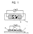
- the carrier substrate was provided with lead electrodes of approximately 2 ⁇ m thickness, between which a 0.5 ⁇ 6 mm wide strip was produced using a mask. After removing the mask, the actual sensor was created in this strip, the resistance of the sensor being continuously monitored during the measurement. With a total resistance of 8 M ⁇ , the evaporation was ended and the finished measuring strip on the cleaned surface of a Stainless steel stick glued (Fig. 1). The distance between the electrodes is 0.5 mm, the width of the film 6 mm.
- f represents the substrate, d the evaporated gold film, e the lead electrodes, s the stainless steel substrate to be examined and R the resistance measuring device.
- the strains were varied between 10 ⁇ 6 and 2 ⁇ 10 ⁇ 5.
- Fig. 2 shows the change in resistance ⁇ R (k ⁇ ) of the measuring strip as a function of the duration of the various loads, the sharp peaks that occur in the loaded states ⁇ 1 and ⁇ 4 caused by vibrations when lifting the loads.
- ⁇ R / R ⁇ 10 ⁇ 4 versus ⁇ ⁇ 10 ⁇ 6 are plotted as resistance-strain characteristics, a linear change in resistance results in the strain range.
- the surface resistance of the strain gauge changes reversibly in the temperature range between 253 and 293 K.
- the "aging process”, i.e. the gradual changes in the resistance of the measuring strips produced in this way are completed within a few days under normal ambient conditions.
Landscapes
- Physics & Mathematics (AREA)
- General Physics & Mathematics (AREA)
- Engineering & Computer Science (AREA)
- Microelectronics & Electronic Packaging (AREA)
- Measurement Of Length, Angles, Or The Like Using Electric Or Magnetic Means (AREA)
Claims (3)
- Jauge extensométrique constituée essentiellement d'une couche métallique mince discontinue (d), dont l'effet de conduction repose principalement sur l'effet tunnel, appliquée uniformément sur un substrat mince diélectrique non métallique (f), l'interaction entre ce substrat et la couche métallique diminuant les phénomènes de diffusion dans la couche métallique appliquée, caractérisée par le fait que le substrat (f) est un film de plastique étiré uniaxialement.
- Jauge extensométrique selon la revendication 1, caractérisée par le fait que le substrat est une couche ultramince ordonnée d'épaisseur inférieure à 0,1 µm.
- Jauge extensométrique selon la revendication 1, caractérisée par le fait que la couche métallique (d), constituée d'étain, d'indium, de zinc ou de cadmium, est déposée épitaxiquement sur le substrat.
Priority Applications (1)
| Application Number | Priority Date | Filing Date | Title |
|---|---|---|---|
| DE8787101733T DE3769305D1 (de) | 1987-02-09 | 1987-02-09 | Dehnungsmessstreifen mit einer duennen diskontinuierlichen metallschicht. |
Applications Claiming Priority (1)
| Application Number | Priority Date | Filing Date | Title |
|---|---|---|---|
| DE19863603449 DE3603449A1 (de) | 1986-02-05 | 1986-02-05 | Dehnungsmessstreifen mit einer duennen diskontinuierlichen metallschicht |
Publications (3)
| Publication Number | Publication Date |
|---|---|
| EP0278021A2 EP0278021A2 (fr) | 1988-08-17 |
| EP0278021A3 EP0278021A3 (en) | 1988-10-05 |
| EP0278021B1 true EP0278021B1 (fr) | 1991-04-10 |
Family
ID=6293375
Family Applications (1)
| Application Number | Title | Priority Date | Filing Date |
|---|---|---|---|
| EP87101733A Expired - Lifetime EP0278021B1 (fr) | 1986-02-05 | 1987-02-09 | Jauges de contrainte à résistance avec une couche mince métallique discontinue |
Country Status (4)
| Country | Link |
|---|---|
| US (1) | US4812800A (fr) |
| EP (1) | EP0278021B1 (fr) |
| JP (1) | JPS62185102A (fr) |
| DE (1) | DE3603449A1 (fr) |
Families Citing this family (11)
| Publication number | Priority date | Publication date | Assignee | Title |
|---|---|---|---|---|
| US5134248A (en) * | 1990-08-15 | 1992-07-28 | Advanced Temperature Devices, Inc. | Thin film flexible electrical connector |
| DE4408043C2 (de) * | 1994-03-10 | 1997-11-13 | Hochtief Ag Hoch Tiefbauten | Vorrichtung zum Überwachen der Spannkraft eines Spannelementes |
| US5679888A (en) * | 1994-10-05 | 1997-10-21 | Matsushita Electric Industrial Co., Ltd. | Dynamic quantity sensor and method for producing the same, distortion resistance element and method for producing the same, and angular velocity sensor |
| KR0174872B1 (ko) * | 1995-12-08 | 1999-02-01 | 양승택 | 압 저항 소자 및 그의 제조방법 |
| DE69825939T2 (de) * | 1997-05-30 | 2005-09-15 | Matsushita Electric Industrial Co., Ltd., Kadoma | Anordnung mit Quanten-Schachteln |
| AUPR725601A0 (en) * | 2001-08-24 | 2001-09-20 | Commonwealth Scientific And Industrial Research Organisation | Strain gauges |
| JP4150013B2 (ja) * | 2005-03-31 | 2008-09-17 | Tdk株式会社 | トンネル効果素子 |
| DE102006004922B4 (de) | 2006-02-01 | 2008-04-30 | Nanoscale Systems Nanoss Gmbh | Miniaturisiertes Federelement und Verfahren zu dessen Herstellung, Balkensonde, Rasterkraftmikroskop sowie Verfahren zu dessen Betrieb |
| US9121258B2 (en) | 2010-11-08 | 2015-09-01 | Baker Hughes Incorporated | Sensor on a drilling apparatus |
| US9057247B2 (en) * | 2012-02-21 | 2015-06-16 | Baker Hughes Incorporated | Measurement of downhole component stress and surface conditions |
| WO2019195618A1 (fr) * | 2018-04-04 | 2019-10-10 | The Regents Of The University Of California | Mesures sans contact de fluides, de particules et de bulles |
Family Cites Families (3)
| Publication number | Priority date | Publication date | Assignee | Title |
|---|---|---|---|---|
| US2556132A (en) * | 1948-10-28 | 1951-06-05 | Chrysler Corp | Strain gauge |
| US2621276A (en) * | 1949-12-09 | 1952-12-09 | Lockheed Aircraft Corp | Electrical strain gauge and method of making same |
| DE2916425C2 (de) * | 1979-04-23 | 1981-04-09 | Siemens AG, 1000 Berlin und 8000 München | Dehnungsmeßstreifen und Verfahren zu seiner Herstellung |
-
1986
- 1986-02-05 DE DE19863603449 patent/DE3603449A1/de not_active Withdrawn
-
1987
- 1987-01-23 JP JP62012626A patent/JPS62185102A/ja active Pending
- 1987-02-05 US US07/010,995 patent/US4812800A/en not_active Expired - Fee Related
- 1987-02-09 EP EP87101733A patent/EP0278021B1/fr not_active Expired - Lifetime
Also Published As
| Publication number | Publication date |
|---|---|
| JPS62185102A (ja) | 1987-08-13 |
| DE3603449A1 (de) | 1987-08-06 |
| EP0278021A2 (fr) | 1988-08-17 |
| EP0278021A3 (en) | 1988-10-05 |
| US4812800A (en) | 1989-03-14 |
Similar Documents
| Publication | Publication Date | Title |
|---|---|---|
| EP1535035B1 (fr) | Systeme de protection contre l'humidite pour un transducteur electromecanique | |
| EP0087419B1 (fr) | Jauge de contrainte a couche mince et procede pour sa fabrication | |
| EP0278021B1 (fr) | Jauges de contrainte à résistance avec une couche mince métallique discontinue | |
| DE2913772C3 (de) | Halbleiter-Druckwandler | |
| EP0667514B1 (fr) | Jauge de contrainte et méthode de sa fabrication | |
| EP0019135A2 (fr) | Sonde pour l'application à la mesure de la température ou de la masse d'un milieu en écoulement et procédé pour sa fabrication | |
| DE3403042A1 (de) | Duennfilm-dehnungsmessstreifen-system und verfahren zu seiner herstellung | |
| DE3025996C2 (de) | Verfahren zur Herstellung eines Wegaufnehmers | |
| EP0226572B1 (fr) | Appareil de mesure utilisant un film piézoélectrique flexible comme élément de mesure | |
| DE3032476A1 (de) | Selektiver duennschicht-gassensor hoher empfindlichkeit und stabilitaet zum nachweis und zur messung von gasfoermigen kohlenwasserstoff-verunreinigungen in der luft auf der basis von wolframoxid (wo(pfeil abwaerts)x(pfeil abwaerts))-halbleitern, sowie ein verfahren zu seiner herstellung | |
| EP0191785A1 (fr) | Procede de fabrication d'une sonde de mesure destinee a la mesure de la temperature ou de la masse d'un fluide en ecoulement | |
| EP0017982B1 (fr) | Jauge de contrainte et sa fabrication | |
| DE102010054970B4 (de) | Vorrichtung zum Wandeln einer Dehnung und/oder Stauchung in ein elektrisches Signal, insbesondere Dehnungsmessfolie | |
| DE69204936T2 (de) | Dehnungsempfindliche Dünnschicht auf Cermet-Basis aus Tantal und Tantalnitrid, deren Verfahren zur Herstellung und deren Anwendung in einem Drucksensor. | |
| DE102007011878A1 (de) | Isolatorschichtsystem für einen Sensor und Sensor mit einem solchen Isolatorschichtsystem | |
| EP0992778A2 (fr) | Capteur et son procédé de fabricage | |
| DE3410578A1 (de) | Duennfilm-feuchtigkeitsmessfuehler | |
| DE3421963C2 (fr) | ||
| DE1279242B (de) | Elektronisches Festkoerperbauelement zum Schalten | |
| DE2908919C2 (de) | Verfahren zur Herstellung eines Dünschichttemperatursensors | |
| DE2902241C3 (de) | Verfahren zum Aufstäuben einer metallischen Dünn-Schicht auf einem Substrat aus Kunststoff | |
| DE19936856C1 (de) | Verfahren zum Herstellen eines Bauelements, insbesondere Foliendehnungsmeßstreifenelements, sowie Foliendehnungsmeßstreifenelement | |
| EP1380832A2 (fr) | Procédé d'estimation des propriétés d'adhérence de matériaux | |
| DE2902244A1 (de) | Dehnungsmesstreifen mit aufgedampftem oder aufgestaeubtem messgitter | |
| DE3447001A1 (de) | Verfahren zur herstellung einer feuchtigkeitsdurchlaessigen elektrode fuer feuchtigkeitsmessfuehler |
Legal Events
| Date | Code | Title | Description |
|---|---|---|---|
| PUAI | Public reference made under article 153(3) epc to a published international application that has entered the european phase |
Free format text: ORIGINAL CODE: 0009012 |
|
| AK | Designated contracting states |
Kind code of ref document: A2 Designated state(s): CH DE FR GB IT LI NL |
|
| PUAL | Search report despatched |
Free format text: ORIGINAL CODE: 0009013 |
|
| AK | Designated contracting states |
Kind code of ref document: A3 Designated state(s): CH DE FR GB IT LI NL |
|
| 17P | Request for examination filed |
Effective date: 19880909 |
|
| 17Q | First examination report despatched |
Effective date: 19900306 |
|
| GRAA | (expected) grant |
Free format text: ORIGINAL CODE: 0009210 |
|
| AK | Designated contracting states |
Kind code of ref document: B1 Designated state(s): CH DE FR GB IT LI NL |
|
| ITF | It: translation for a ep patent filed | ||
| REF | Corresponds to: |
Ref document number: 3769305 Country of ref document: DE Date of ref document: 19910516 |
|
| GBT | Gb: translation of ep patent filed (gb section 77(6)(a)/1977) | ||
| ET | Fr: translation filed | ||
| PLBE | No opposition filed within time limit |
Free format text: ORIGINAL CODE: 0009261 |
|
| STAA | Information on the status of an ep patent application or granted ep patent |
Free format text: STATUS: NO OPPOSITION FILED WITHIN TIME LIMIT |
|
| 26N | No opposition filed | ||
| PGFP | Annual fee paid to national office [announced via postgrant information from national office to epo] |
Ref country code: FR Payment date: 19960122 Year of fee payment: 10 |
|
| PGFP | Annual fee paid to national office [announced via postgrant information from national office to epo] |
Ref country code: NL Payment date: 19960129 Year of fee payment: 10 |
|
| PGFP | Annual fee paid to national office [announced via postgrant information from national office to epo] |
Ref country code: GB Payment date: 19960201 Year of fee payment: 10 |
|
| PGFP | Annual fee paid to national office [announced via postgrant information from national office to epo] |
Ref country code: CH Payment date: 19960207 Year of fee payment: 10 |
|
| PGFP | Annual fee paid to national office [announced via postgrant information from national office to epo] |
Ref country code: DE Payment date: 19960224 Year of fee payment: 10 |
|
| PG25 | Lapsed in a contracting state [announced via postgrant information from national office to epo] |
Ref country code: GB Effective date: 19970209 |
|
| PG25 | Lapsed in a contracting state [announced via postgrant information from national office to epo] |
Ref country code: DE Effective date: 19970224 |
|
| PG25 | Lapsed in a contracting state [announced via postgrant information from national office to epo] |
Ref country code: LI Effective date: 19970228 Ref country code: CH Effective date: 19970228 |
|
| PG25 | Lapsed in a contracting state [announced via postgrant information from national office to epo] |
Ref country code: NL Effective date: 19970901 |
|
| GBPC | Gb: european patent ceased through non-payment of renewal fee |
Effective date: 19970209 |
|
| REG | Reference to a national code |
Ref country code: CH Ref legal event code: PL |
|
| PG25 | Lapsed in a contracting state [announced via postgrant information from national office to epo] |
Ref country code: FR Effective date: 19971030 |
|
| NLV4 | Nl: lapsed or anulled due to non-payment of the annual fee |
Effective date: 19970901 |
|
| REG | Reference to a national code |
Ref country code: FR Ref legal event code: ST |
|
| PG25 | Lapsed in a contracting state [announced via postgrant information from national office to epo] |
Ref country code: IT Free format text: LAPSE BECAUSE OF NON-PAYMENT OF DUE FEES;WARNING: LAPSES OF ITALIAN PATENTS WITH EFFECTIVE DATE BEFORE 2007 MAY HAVE OCCURRED AT ANY TIME BEFORE 2007. THE CORRECT EFFECTIVE DATE MAY BE DIFFERENT FROM THE ONE RECORDED. Effective date: 20050209 |