EP0277760B1 - Verfahren zur Durchführung einer beschleunigten Oxydationsreaktion - Google Patents
Verfahren zur Durchführung einer beschleunigten Oxydationsreaktion Download PDFInfo
- Publication number
- EP0277760B1 EP0277760B1 EP88300668A EP88300668A EP0277760B1 EP 0277760 B1 EP0277760 B1 EP 0277760B1 EP 88300668 A EP88300668 A EP 88300668A EP 88300668 A EP88300668 A EP 88300668A EP 0277760 B1 EP0277760 B1 EP 0277760B1
- Authority
- EP
- European Patent Office
- Prior art keywords
- oxygen
- stream
- water
- reaction
- waste
- Prior art date
- Legal status (The legal status is an assumption and is not a legal conclusion. Google has not performed a legal analysis and makes no representation as to the accuracy of the status listed.)
- Expired - Lifetime
Links
Images
Classifications
-
- C—CHEMISTRY; METALLURGY
- C02—TREATMENT OF WATER, WASTE WATER, SEWAGE, OR SLUDGE
- C02F—TREATMENT OF WATER, WASTE WATER, SEWAGE, OR SLUDGE
- C02F3/00—Biological treatment of water, waste water, or sewage
- C02F3/02—Aerobic processes
- C02F3/06—Aerobic processes using submerged filters
-
- C—CHEMISTRY; METALLURGY
- C02—TREATMENT OF WATER, WASTE WATER, SEWAGE, OR SLUDGE
- C02F—TREATMENT OF WATER, WASTE WATER, SEWAGE, OR SLUDGE
- C02F11/00—Treatment of sludge; Devices therefor
- C02F11/06—Treatment of sludge; Devices therefor by oxidation
- C02F11/08—Wet air oxidation
- C02F11/083—Wet air oxidation using deep well reactors
-
- B—PERFORMING OPERATIONS; TRANSPORTING
- B01—PHYSICAL OR CHEMICAL PROCESSES OR APPARATUS IN GENERAL
- B01J—CHEMICAL OR PHYSICAL PROCESSES, e.g. CATALYSIS OR COLLOID CHEMISTRY; THEIR RELEVANT APPARATUS
- B01J3/00—Processes of utilising sub-atmospheric or super-atmospheric pressure to effect chemical or physical change of matter; Apparatus therefor
- B01J3/04—Pressure vessels, e.g. autoclaves
- B01J3/042—Pressure vessels, e.g. autoclaves in the form of a tube
-
- C—CHEMISTRY; METALLURGY
- C02—TREATMENT OF WATER, WASTE WATER, SEWAGE, OR SLUDGE
- C02F—TREATMENT OF WATER, WASTE WATER, SEWAGE, OR SLUDGE
- C02F11/00—Treatment of sludge; Devices therefor
- C02F11/06—Treatment of sludge; Devices therefor by oxidation
- C02F11/08—Wet air oxidation
Definitions
- the present invention relates to improvements in the treatment of waste and other combustible materials in an aqueous fluid stream, such as, for example, organic solvents, municipal sludge, toxic or contaminated products.
- Various wet oxidation treatment processes are disclosed in the prior art.
- the temperature of combustible material dissolved and/or suspended in water in the presence of oxygen is increased to produce a wet oxidation reaction.
- the combustion reaction is exothermic and can be carried out in a reaction apparatus having a continuous heat exchanger such that the heat evolved by the combustion reaction is used to heat an influent waste stream to the desired temperature. This provides an enhanced, energy-efficient system.
- the prior art has also proposed utilizing wet oxidation processes of this type in a continuous vertical heat exchange column which may be supported in a subterranean well.
- the depth of the well or column determines in part the hydrostatic fluid pressure which is maintained such that boiling of the fluid during the reaction process is prevented.
- the prior art has recognized the possibility of treating organic waste, including municipal sludge, in a deep well reaction vessel having tubes nested to form annuli in a heat exchange relation wherein combustible waste is introduced as an aqueous influent waste stream.
- the combustible waste in the fluid medium is one reactant and oxygen, introduced as a gas, such as, for example, air, is the other reactant.
- the air is injected under pressure into the downgoing influent tube in a manner to premote intense mixing and contacting and to increase the flow of reactants and products through the system.
- the quantity of gas injected into the influent annulus is controlled to provide the proper oxygen-to-waste ratio to bring about the desired reaction, as more fully disclosed in US- A- 4 272 383, which is assigned to the Applicant of the present Application.
- the influent waste or waste stream is pumped from the ground surface downwardly into the influent annulus at a controlled temperature, pressure and flow rate.
- the fluid waste forms a hydrostatic column having the desired pressure and temperature at a reaction zone deep within the reaction vessel. Under these conditions, the reactants react at an accelerated rate.
- the heated fluid and reaction products are then flowed upwardly through the effluent annulus to ground surface.
- the influent and effluent annuli are preferably in heat exchange relation to best utilize the reaction heat.
- the temperature of the fluid in the reaction zone is controlled, preferably by adding or removing heat from the system. This can be achieved by placing a vertical heat exchange apparatus in the reactor assembly as shown in the disclosed preferred embodiment.
- the overall efficiency of a downhole or deep well reactor apparatus of the general type described may be improved by using pure oxygen or oxygen-rich gas for injection rather than air because air contains only about 21 percent by volume oxygen.
- air contains only about 21 percent by volume oxygen.
- the wet oxidation reaction is enhanced.
- the prior art does in fact suggest the injection of oxygen-enriched air or even pure oxygen into an oxidation reaction vessel (see for example US- A- 3 449 247).
- the injection of substantially pure oxygen, oxygen-enriched air or other oxygen-enriched gas into the influent annulus can, however, cause an unwanted and potentially hazardous form of combustion resulting from dry spots produced in the reactor.
- the injection of dry oxygen-enriched gases into the reactor may create dry areas of combustible material which can ignite in the dry, oxygen-rich environment. Also, when exposed to a dry, oxygen-rich gas, the tube wall itself may actually ignite. This series of events can cause catastrophic failure of the reactor.
- US- A- 3 449 247 also discloses the injection of a gas reactant at either the top or the bottom of the reactor well. Since a column of "pure" liquid has greater density and thus weighs more than the same liquid containing a gas, lowering the point of injection of the reactant gas in the influent annulus increases the fluid pumping efficiency. Unfortunately, the energy saved in lowering the point of injection of the reactant gas may be substantially offset by that required to pressurize the reactant gas to the pressure of the influent fluid at this low point of injection. The prior art does not suggest any improvement in the efficiency of the wet oxidation process resulting from lowering the point of injection of the reactant gas.
- the method of the present invention provides a safe and efficient manner of introducing oxygen, oxygen-enriched air or an oxygen-rich gas directly into the influent waste stream in the reaction apparatus.
- a composition containing substantially pure gaseous oxygen or oxygen-rich gas as one component is injected into the influent annulus at multiple sites, including at least one injection point near the reaction zone.
- a method for introducing gaseous oxygen into a fluid waste stream in conjunction with the accelerated oxidation of organic matter inside a reaction apparatus comprising the steps of: preparing a multiple-phase composition which contains gaseous oxygen which is substantially fully saturated with water vapour, the multiple-phase composition also containing liquid water; injecting said multiple-phase composition into the fluid waste stream in the reaction apparatus in pulses at at least one injection site; and raising the temperature and pressure of the fluid waste stream containing the multiple-phase composition to produce the accelerated oxidation reaction of organic matter, the quantity of liquid water in the multiple-phase composition being sufficient to maintain at least a portion in the liquid phase in the environment of the fluid waste stream, whereby unwanted dry spots which could otherwise form in the reaction apparatus are substantially eliminated.
- a method of effecting an accelerated wet oxidation reaction of combustible material in a fluid stream in a wet aqueous phase oxidation apparatus which comprises flowing the fluid stream containing the combustible material through a passage in the wet oxidation apparatus and subjecting the fluid stream containing the combustible material to a pressure and temperature sufficient to oxidize the combustible material at an accelerated reaction rate, injecting a concurrent stream of a gas and liquid water in pulses into the fluid stream in the passage, wherein the total volume of water is equal to at least twice the volume of water necessary to saturate the gas with water vapour and wherein the gas is selected from substantially pure oxygen and oxygen-rich gas.
- a method of effecting an accelerated wet oxidation reaction of an aqueous stream of combustible waste to form reaction products in a vertical well wet oxidation apparatus of the type having a plurality of generally concentric tubes extending generally vertically to a selected depth below the ground surface, the tubes defining at least a first and second passage which comprises the steps of: providing a plurality of injection sites in the first passage; flowing said aqueous stream of combustible waste into the first passage to form a hydrostatic column having a selected pressure; elevating the temperature of the aqueous stream of combustible waste; injecting in pulses into the aqueous stream of combustible waste in the first passage at the injection sites a pressurized concurrent stream of a gas and liquid water, the gas being selected from substantially pure oxygen and an oxygen-rich gas, and wherein the gas is saturated with water vapour at the pressure of the pressurized concurrent stream and at the temperature of the aqueous
- a method of effecting accelerated oxidation of a combustible aqueous organic waste in a vertical well reactor having a plurality of generally concentric nested tubes defining communicating downcomer and upcomer annuli extending generally vertical to a selected depth below the ground surface which comprises flowing an aqueous stream of the combustible organic waste into the downcomer annulus to form a hydrostatic column having a selected pressure, the hydrostatic column having a reaction zone, elevating the temperature of the aqueous stream, introducing in pulses a concurrent stream of oxygen-rich gas and liquid water under pressure into the downcomer annulus, the volume of water in the concurrent stream being at least twice the volume necessary to saturate the oxygen-rich gas with water vapour at the temperature and pressure of the fluid column in the downcomer annulus at the point of introduction and maintain water in the liquid phase, the combustible organic waste material reacting with the oxygen forming oxidation reaction products, and returning the
- a method for producing a controlled, accelerated oxidation reaction of organic matter in an aqueous stream inside a downcomer passage of a vertical tube reaction apparatus which comprises the steps of preparing a multiple-phase composition containing both an oxygen-rich gas which is fully saturated with water vapour and which also contains liquid water, pulsing the multiple-phase composition through at least one injection site into the aqueous stream of organic matter near the top of the downcomer passage to churn the aqueous stream of organic matter to prevent fouling of the downcomer passage and to reduce pumping pressure, raising the temperature and pressure of the aqueous stream of organic matter to produce the controlled accelerated oxidation reaction.
- the present invention also provides a method for introducing gaseous oxygen into a fluid waste stream in conjunction with the accelerated oxidation of organic matter inside a reaction apparatus, comprising the steps of: injecting the gaseous oxygen in pulses into the fluid waste stream in the reaction apparatus at at least one reaction site; and raising the temperature and pressure of the fluid waste stream containing the gaseous oxygen to produce the accelerated oxidation reaction of organic matter.
- a method for introducing oxygen, oxygen-enriched air or an oxygen-rich gas into an influent combustible waste stream in a wet oxidation reaction apparatus which prevents the formation of dry spots.
- the method includes flowing a fluid stream containing combustible waste through the influent annulus or passage of a reaction apparatus, elevating the temperature and pressure of the influent waste stream, and injecting a multiple-phase composition which contains gaseous oxygen, or an oxygen-rich gas, which is fully saturated with the water vapor, and which also contains liquid water.
- the multiple-phase composition comprises pure oxygen or oxygen-rich gas which is fully saturated with water vapor and which also includes a liquid water phase, the liquid water phase being present in an amount which is equal to the amount of water present in the vapor phase.
- the quantity of water added to the gas is great enough such that 50 percent by volume of the water is present in liquid phase and 50 percent is present in the vapor phase at injection temperature and pressure.
- the method thus contemplates preparing a multiple-phase composition of an oxygen-rich gas which is fully saturated with water vapor and which also contains liquid water and injecting this multiple-phase composition into the liquid waste stream in the wet oxidation reaction apparatus.
- the stream of gas and liquid water is injected into the fluid stream of combustible material at multiple locations along the influent reactor annulus or passage.
- the process is carried out in a vertical well wet oxidation reaction apparatus having a plurality of tubes which extend generally vertically to a selected depth below the earth's surface.
- the preferred method comprises flowing a fluid waste stream containing a combustible waste down an influent annulus or passage to form a hydrostatic column of substantial fluid pressure.
- the temperature of the fluid is increased sufficiently to support a wet oxidation reaction.
- the improved method includes injecting a concurrent stream of pure oxygen, or an oxygen-rich gas, and liquid water into the influent passage at the pressure of the waste fluid in the influent passage at the point of injection whereby the oxygen reactant is safely introduced into the reaction apparatus by eliminating the formation of dry spots.
- the total volume of water in the oxygen stream must be greater than the volume necessary to fully saturate the gas at the injection temperature and pressure, i.e. the equilibrium vapor pressure, and still maintain a quantity of water in the liquid phase.
- the oxidation reaction products and water are returned to the ground surface through an effluent annulus or passage communicating with the influent passage, preferably in heat transfer relation.
- the method of effecting an accelerated oxidation reaction of this invention is preferably utilized to treat a mixture of suspended and dissolved organic material in an aqueous waste stream such as municipal sludge.
- an aqueous waste stream such as municipal sludge.
- the municipal sludge is preferably diluted with water prior to its introduction in the deep well reaction apparatus.
- the reaction temperature at which the oxidation reaction is self-sustaining in the apparatus of US- A-4 272 383 is approximately 260°C (500°F), and approximately a 70 percent COD (chemical oxygen demand) reduction of the organic waste material is achieved.
- the introduction of pure gaseous oxygen or substantially pure gaseous oxygen into the influent waste in the reaction apparatus near ground level by pulse injection results in substantial agitation of the organic-laden influent. This reduces organic growth and fouling of the influent passage and, accordingly, reduces the pumping pressure required to move material through the reaction apparatus.
- the pressure of the oxygen or oxygen-rich gas supplied to the waste in the present invention is approximately 13790 kPa (2000 pounds per square inch) which is approximately the hydrostatic column in the influent tube at about 914 to 1219 metres (3000-4000 feet) below ground level.
- the oxygen and liquid water combination of the present invention may be introduced into the downwardly flowing fluid in the influent tube at approximately as far down as 914 to 1219 metres (3000-4000 feet) below ground level without requiring any additional pressurization.
- the multiple-phase composition supply line is disposed through the inlet of the influent annulus which maintains the temperature of the oxygen and liquid water at substantially the temperature of the influent fluid, thus equalling both the pressure and temperature of the influent fluid at the point of injection in the reactor.
- the present invention provides a method for initiating an accelerated wet oxidation reaction in a aqueous fluid stream of combustible waste inside a reaction apparatus wherein the lines or pipes through which the multiple-phase composition is delivered to the waste are "purged" of unwanted combustible impurities and by which the multiple-phase composition can be formed and injected without producing a flow of dry oxygen or dry oxygen-rich gas through a substantial portion of the waste treatment apparatus.
- a method to shut down the system is provided by which the flow of dry oxygen or dry oxygen-rich gas is avoided through any substantial portion of the system.
- start-up the flow of diluted influent waste as an influent waste stream is commenced.
- an inert gas is continuously flowed through the supply lines and into the suspended fluid waste inside the reactor.
- a stream of liquid water is introduced into the supply line such that both water and the inert gas flow through the lines together into the waste in the reactor.
- a detergent solution is then flowed through the lines along with the inert gas to remove debris from the supply lines. It is preferred that an aqueous detergent solution be used for this purpose.
- the cleaned lines are then rinsed by flowing liquid water without the detergent solution through the lines.
- oxygen or an oxygen-rich gas is introduced into and flowed through the supply lines.
- oxygen or oxygen-rich gas, inert gas, and liquid water are contemporaneously flowed through the supply lines and into the waste inside the reaction apparatus.
- the flow of inert gas is stopped and the flow of oxygen and water or oxygen-rich gas and water is regulated to form the multiple-phase composition used in the present invention which is injected into the waste stream in the reaction apparatus.
- a method is provided whereby the flow of influent waste is first stopped and the effluent stream, from which the ash end-product is substantially removed, is recycled through the reaction apparatus.
- the flow of influent waste is stopped and water is circulated through the reaction apparatus.
- an inert gas is flowed through the gas supply lines along with the multiple-phase composition, again diluting the concentration of oxygen.
- the flow of oxygen or oxygen-rich gas is stopped, leaving only water and inert gas flowing through the lines. The water and inert gas are then discontinued in any order.
- the method of the present invention for producing the accelerated oxidation reaction of a combustible material therefore permits the injection of pure oxygen or oxygen-rich gas into the waste stream in the reaction apparatus and avoids the aforementioned safety hazards associated with introduction of dry oxygen into a combustion system. Further, the oxygen and water composition is injected into the aqueous influent waste stream in the reaction apparatus at predetermined locations to control the oxidation reaction as desired.
- the method of this invention further eliminates the requirement of a continuous supply of inert gas, reducing cost and increasing reaction vessel capacity by increasing volume availability for oxygen.
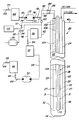
- Figure 1 is a schematic illustration of an embodiment of an apparatus which may be used in the method of effecting accelerated oxidation reaction of this invention.
- the continuous fluid treatment apparatus 20 illustrated in Figure 1 is a vertical downhole or deep well fluid reaction apparatus suitable for wet oxidation treatment of various combustible materials in an aqueous fluid stream, including suspended and/or dissolved organic waste, such as, for example, diluted municipal sludge.
- the preferred fluid treatment apparatus comprises a plurality of generally concentric, nested pipes or tubes which extend vertically below ground level.
- the tubes may extend approximately 1600 metres (one mile) into the ground to define annuli which, when filled with a fluid waste stream, create a hydrostatic column of very substantial fluid pressure.
- each tube typically comprises a plurality of sections which are interconnected in serial alignment in a string, similar to the pipes in an oil well.
- the length of each pipe is about 12 metres (40 feet) long and the total length is about 1585 metres (5,200 feet).
- the flow rate through the reactor of the fluid being treated typically ranges from about 303 to 1514 litres per minute (about 80 to about 400 gallons per minute) in substantially continuous operation.
- the exterior or outermost tube 22 surrounds tube 24 to define upcomer passage or annulus 25.
- Tube 24 surrounds a heat exchanger 26 to define downcomer passage or annulus 27.
- heat exchanger 26 is utilized to control the temperature of the reaction vessel, whereby heat may be added or removed.
- the disclosed embodiment of heat exchanger 26 includes downcomer pipe 28, which is surrounded by upcomer pipe 30 to define annulus 31. Oil, water, steam or other heat exchange medium is circulated through heat exchanger 26 to heat or cool the reaction vessel when required.
- aqueous waste which contains combustible material is introduced into downcomer annulus 27 as an influent waste stream and flows downwardly through annulus 27 which is in contact with heat exchanger 26.
- a wet oxidation reaction typically begins at about 305 to 610 metres (1000-2000 feet) below ground surface at a fluid waste stream temperature of about 177°C (350°F). The reaction proceeds slowly as the fluid waste stream continues to flow downwardly and the temperature of the fluid waste stream increases to about 260°C (500°F) at approximately 914 to 1524 metres (3000 to 5000 feet) below ground level.
- heated oil is supplied to downcomer pipe 28, which is preferably an insulated tubular pipe.
- the heated oil then flows downwardly through the insulated tubular pipe until it reaches the open end 36, concentrating the heat transferred to the circulating fluid being treated in the reaction zone at the lower end of the apparatus.
- Figure 1 also illustrates schematically the preferred method of injecting the oxygen reactant safely into the reaction apparatus.
- oxygen-rich or “oxygen-enriched” gas mean any gas which includes oxygen in a concentration greater than the concentration of oxygen in air and includes pure oxygen, oxygen-enriched air, and oxygen plus inert or active constituents depending upon the exact nature of the reaction to be carried out.
- the oxygen-rich gas it is preferred that the oxygen-rich gas contain at least 90 percent oxygen by volume. In some applications, it may be possible to practice the present invention with other gases or gas mixtures.
- dry, oxygen-rich gas or dry pure oxygen in the presence of a dry combustible material is relatively hazardous since it may ignite violently as is known.
- the use of dry, oxygen-rich gas in a wet oxidation reaction apparatus can result in "hot spot" ignition of the combustible material if the combustible material is allowed to dry, causing damage to the apparatus.
- dry oxygen-rich gas is injected using conventional methods, the gas may dry an area of the wall resulting in ignition of dry combustible material such as, for example, scale, particularly where the oxygen-rich gas is injected below ground surface level where, as explained, the fluid is heated and thus tends to evaporate more rapidly.
- the ignition of the dry organic matter in the presence of oxygen may ignite the reactor materials, resulting in serious damage and destruction of the tube. With certain metal alloys used to construct some tube-type reactors, regions of metal may even ignite.
- the apparatus shown in Figure 1 includes an insulated storage tank for liquid oxygen 46, including supply line 44 and valves 48 at the inlet and outlet of the tank.
- liquid oxygen can be purchased commercially.
- liquid oxygen may be stored at a pressure of about 345 kPa (50 pounds per square inch) at a temperature of about -162°C (-260°F).
- liquid oxygen is flowed on a demand basis through line 49 at a conventional liquid oxygen pump 50 which pressurizes the liquid oxygen to about 13790 kPa (2000 pounds per square inch).
- a suitable liquid oxygen pump is a small, single stage reciprocal pump which is illustrated generically in the drawing.
- a pressure of about 13790 kPa (2000 psi) is an efficient pressure for transporting the liquid oxygen to the point of use.
- the liquid oxygen is then pumped to a liquid oxygen atmospheric vaporizer 52 through line 54.
- Liquid oxygen atmospheric vaporizers are heat exchangers, available commercially, which efficiently convert a gas from the liquid phase to gaseous phase.
- Substantially pure oxygen in the gaseous phase, near ambient temperature, is then received in line 58.
- the pressure remains at about 13790 kPa (2000 psi).
- the gaseous oxygen is then received and stored in a storage bottle or tank 56.
- the hazards associated with injecting an oxygen-rich gas into the influent stream of the reaction apparatus is materially reduced through the present invention by injecting a concurrent stream of oxygen-rich gas and liquid water.
- water is stored in tank 66.
- the water is received through inlet 68 from a suitable source.
- the water flow is controlled by inlet and outlet valves 70.
- Water is delivered through line 74 to pump 72 to be pumped to the desired pressure.
- Water is pumped through line 76 into oxygen line 62 and the volume of water pumped into the oxygen line is controlled by valve 78.
- the volume of oxygen pumped into the line is controlled by the flow control valve 60 which includes conventional safety devices required for handling an oxygen-rich gas.
- the preferred method of this invention includes injecting the oxygen-rich gas and liquid water at multiple vertically-spaced locations in downcomer annulus 27 of reaction apparatus 20.
- Figure 1 shows two injection lines 80 and 82, which are controlled by valves 84 and 86. It will be understood, however, that several injection lines may be utilized.
- a second gas such as air, nitrogen, or other inert gas may be combined with substantially pure oxygen to create an oxygen-rich gas or gaseous mixture.
- the oxygen-rich gas preferably contains at least 50 percent oxygen by volume, although lesser amounts may achieve some beneficial results.
- the disclosed apparatus therefore may include an air compressor 90 wherein the compressed air may be delivered through line 92 to line 62.
- the ratio of oxygen to air may be controlled by valves 94 and 96.
- Water is normally utilized as a coolant and a flame retarder in the method of this invention because it is efficient, readily available, inexpensive and because water is normally utilized as the fluid carrier in wet oxidation reactions. It may be possible to use some other substance with characteristics similar to water in some applications.
- the sludge is preferably diluted with water prior to delivery of the sludge to the reaction apparatus.
- various constituents may be added to the water, including surfactants, cleaning or scale-inhibiting additives and reactants.
- the oxygen used in the method of this invention may be generated at the point of use if the demand is sufficiently large. For example, a greater demand of oxygen may be met with a conventional vacuum swing adsorption air separator unit or a substantial demand may be met with a cryogenic air separation plant located at the site of the wet oxidation reaction apparatus.
- the preferred method of generating oxygen in the method of this invention will depend upon the volume of combustible material processed by the reaction apparatus 20.
- a deep well wet oxidation reaction apparatus of the type shown in Figure 1 which is processing less than about 9 metric tons (10 tons) of sludge per day, the use of commercially available liquid oxygen may be preferred.
- the present invention thus provides a novel method of injecting oxygen or an oxygen-rich gas directly into an aqueous waste stream in a wet oxidation reaction apparatus.
- a multiple-phase composition which contains gaseous oxygen that is fully saturated with water vapor and which also contains water in the liquid phase is prepared and injected into the influent liquid waste stream in the downcomer annulus 27.
- This multiple-phase composition is to be distinguished from stream which when heated may dry out combustible material in the reaction apparatus and cause the type of unwanted combustion which the present invention eliminates.
- the amount of liquid phase water present in the multiple-phase composition can be adjusted within the guidelines of the present invention for a particular reaction.
- the volume of water which is injected into the liquid waste along with the gaseous oxygen must be great enough so that water is at least partially present in the liquid phase.
- the volume of water added to the oxygen or oxygen-rich gas must be greater than the volume necessary to fully saturate the oxygen-rich gas at the injection temperature and pressure and great enough so that at least some water in the liquid phase is maintained at all times during the wet oxidation reaction.
- the total volume of water in the multiple-composition is equal to twice the volume of water necessary to fully saturate the oxygen or oxygen-rich gas with water vapor and maintain at least 50 percent of the water in the liquid phase.
- the quantity of liquid phase water be at least equal to the volume of water present as water vapor in the oxygen-rich gas at injection temperature and pressure.
- the total volume of water in the multiple-phase composition is about ten times the volume necessary to fully saturate the oxygen or oxygen-rich gas at injection pressure and temperature, which ensures a substantial safety margin of liquid phase water.
- the pumping pressure adjacent the inlet of annulus 27 is typically about 2069 kPa (300 psi), and the temperature of the fluid waste during start-up may be about 149°C (300°F).
- the vapour pressure of water at 149°C (300°F) is 462 kPa (67 psia).
- the partial pressure of oxygen will be equal to 1689 kPa (245 psia).
- the volume of 0.45 kilogram (one pound) of oxygen at these temperatures and pressures is 31 litres (1.1 cubic feet) and the weight of water is 0.07 kilograms (0.15 pounds).
- the quantity of water required to fully saturate the gaseous oxygen is 0.07 kilograms (0.15 pounds) per minute or 0.076 litres (0.02 gallons) per minute.
- the required volume of water is 0.151 litres (0.04 gallons) per minute for each 0.45 kilogram (pound) per minute of oxygen injected into the system.
- 0.76 litres (0.2 gallons) per minute of water is required for each 0.45 kilogram (pound) per minute of oxygen injected into the influent stream, which provides a safety margin of ten.
- the volume of oxygen injected is, of course, dependent upon the volume of combustible material received in the influent tube and the desired C.O.D. reduction.
- the apparatus shown in Figure 1 includes two oxygen-water injection lines 102 and 104 which extend downwardly through downcomer annulus 27 from adjacent the ground surface level 40.
- Each of the injection lines 102 and 104 are open or may include coventional nozzles at their distal ends, indicated by reference numerals 106 and 108 respectively.
- the volume of the multiple-phase water composition which is injected is controlled by valves 84 and 86.
- the injection pressure must be equal to at least the influent fluid pressure or pump pressure plus the static column pressure at the depth of the nozzle, less the friction drop of the influent fluid.
- the influent or pump pressure at the upper end of downcomer annulus 27 in the disclosed apparatus when processing municipal sludge is typically between about 1379 and 413 kPa (200 and 600 psi). Thus, the injection pressure should be at least 4137 kPa (600 pounds per square inch).
- the influent solids-laden stream has a high degree of fouling which increases the required pumping pressure.
- the preferred embodiment of the present invention includes an injection nozzle 106 located in the reaction apparatus adjacent the ground surface level 40. At this position, the multiple-phase gas and water composition churns the sludge, mechanically breaking the organic growth which otherwise reduces the pumping pressure.
- the oxygen-water injection at the upper nozzle 106 is cycled or pulsed to avoid or prevent fouling in the top portion of downcomer annulus 27. For example, 10 percent by volume of the oxygen reactant may be supplied through upper nozzle 106 in pulses every ten seconds, with each pulse having a one second duration.
- the pulsing agitates the organic material, reducing fouling.
- the pumping pressure of the influent may be reduced while simultaneously preventing unwanted ignition by injecting a multiple-phase gas and water composition further downstream in downcomer annulus 27.
- the accelerated wet oxidation reaction in the disclosed embodiment of the deep well reaction apparatus processing municipal sludge begins at about 305 to 610 metres (1000-2000 feet) down from the ground surface 40, where the temperature may be about 177°C (350°F).
- the pressure of oxygen and water stream is about 13790 kPa (2000 psi).
- the combined oxygen-rich gas and liquid water stream may be injected into the influent tube at a depth of approximately 914 to 1219 metres (3000-4000 feet) without additional pressurization.
- the preferred method of this invention includes a second oxygen-water injection 108 at a depth of about 914 to 1219 metres (3000-4000 feet).
- about 90 percent by volume of the multiple-phase composition may be injected into downcomer annulus 27 through the lower nozzle 108.
- the apparatus may include several injection nozzles. For example, a series of vertically spaced nozzles may be provided in the influent tube as the influent approaches the reaction zone, which is generally the lower part of the downcomer passage where the oxidation reaction is most vigorous.
- the nozzles may be positioned to purposely starve the wet oxidation reaction or, alternatively, to concentrate the reaction in a particular zone.
- the method of effecting an accelerated wet oxidation reaction of the present invention therefore includes flowing an aqueous fluid stream of combustible materials into downcomer annulus 27, and subjecting the fluid stream to sufficient pressure and temperature to oxidize the combustible materials at an accelerated rate while injecting a concurrent stream of an oxygen-rich gas and liquid water under pressure into the fluid stream in downcomer annulus 27 through nozzles 106 and 108.
- the oxygen-water stream is injected into downcomer annulus 27 at a first site adjacent the ground surface 40 in pulses and at a second, vertically spaced location 108 which is most preferably at or near the point of initiation of the wet oxidation reaction.
- injection lines are provided through which the multiple-phase composition of the present invention is delivered to an injection site in the downcomer annulus of the vertical waste reaction apparatus.
- injection lines are first "purged” in the following manner, which is contemplated as being within the scope of the present invention.
- This start-up method ensures that no dry oxygen or dry oxygen-rich gas flows through the system alone, presenting a potential source of unwanted, rapid combustion.
- the flow of influent waste in the form of an influent waste stream is started in the downcomer annulus. That is, the fluid waste is added to the reaction apparatus as an influent stream.
- inert gas is then introduced into the injection lines and flowed therethrough into the influent waste stream.
- inert gas it is mean that a gas or gas mixture is used which could be, for example, nitrogen, which does not adversely react with any of the system components with which it comes in contact.
- Inert gas at source 110 is fed into the system with valve 111 at any convenient point through inert gas line 112 and preferably near the point at which oxygen enters the multiple-phase composition feed line assembly as shown in Figure 1.
- inert gas is flowed through the injection lines, a stream of fluid water is simultaneously flowed through the injection lines, along with the inert gas.
- an aqueous, dilute detergent such as a trisodium phosphate solution or the like
- tank 66 which is then introduced into the injection lines while the inert gas flow through the lines is continued.
- a non-phosphate detergent may be preferable in some applications.
- concentration and composition of the detergent solution is not critical to the practice of this invention and an aqueous solution containing from about 5 to about 10 percent by weight trisodium phosphate is sufficient to clean injection lines. It may be suitable in some applications to start the flow of aqueous detergent solution immediately after the inert gas flow is commenced, eliminating the intermediate water step.
- the flow rate of each material i.e.
- inert gas, detergent solution and such is not crucial but should be sufficient to expeditiously clean injection lines 80 and 82, particularly of any foreign matter such as combustible waste which may have backflowed from the reactor into the injection lines.
- the quantity of aqueous detergent solution required will, of course, vary to some extent according to the dimensions of the injection lines. From about 38 to 379 litres (10 to 100 gallons) and, preferably, about 208 litres (55 gallons) of dilute aqueous detergent will be sufficient for most applications.
- liquid water from tank 66 is again flowed through to remove any detergent residue deposited during the prior step.
- the flow of inert gas through the lines is still maintained. Since the inert gas does not react with the combustible waste in the reactor in an oxidation reaction, the accelerated oxidation reaction is not activated.
- gaseous oxygen or an oxygen-rich gas is flowed through the lines. As the oxygen flow is commenced, the nitrogen flow is stopped. The sequence of the commencement of the oxygen flow and the cessation of the nitrogen flow is not critical, but is preferred that the nitrogen flow be cut out as soon as practical after the oxygen flow is cut in.
- the water flow is still maintained.
- the water flow and oxygen or oxygen-rich gas are then adjusted to provide the multiple-phase composition described herein at the pressurization necessary for injection into the reaction apparatus.
- the accelerated wet oxidation reaction be shut down in the following manner, which is intended to come within the scope of the present invention.
- the effluent stream from which the ash end-product has been substantially removed by settling or the like is then directed into the influent side of the reaction apparatus in place of the influent waste stream.
- the supply of combustible waste can simply be interrupted, allowing the effluent/diluent to continue to flow through the reaction apparatus.
- water can be cycled through the reaction apparatus instead of the effluent/diluent. It will be understood that recycling the effluent/diluent or water in the reaction apparatus eliminates one reactant, the organic waste, and hence the oxidation reaction stops. This shut-down sequence additionally ensures that no combustible unprocessed waste is carried through the reaction apparatus during shut-down.
- an inert gas such as, for example, nitrogen, as previously described, is flowed through the injection lines along with the multiple-phase composition.
- the inert gas effectively dilutes the concentration of oxygen.
- the concentration of oxygen in the injection lines should preferably be less than about 90% oxygen by volume.
- the flow of oxygen is then discontinued, followed by stopping the flow of water. Finally, the flow of inert gas and effluent/diluent are stopped.
- the method of injecting oxygen into the downcomer passage of a wet oxidation apparatus is particularly suitable for the deep well wet oxidation apparatus disclosed.
- this method may also be used in other wet oxidation reaction methods and apparatus, reducing the hazards resulting from the use of an oxygen-rich gas and improving the efficiency of the system.
- the method of this invention is not limited to the wet oxidation of municipal sludge or organic solids, but may also be used in the treatment of various combustible materials, including contaminated or toxic waste in a fluid medium.
- the method may also be used to treat or convert various combustible materials in a fluid reaction requiring elevated temperatures and pressures.
Landscapes
- Chemical & Material Sciences (AREA)
- Organic Chemistry (AREA)
- Life Sciences & Earth Sciences (AREA)
- Environmental & Geological Engineering (AREA)
- Hydrology & Water Resources (AREA)
- Engineering & Computer Science (AREA)
- Water Supply & Treatment (AREA)
- Chemical Kinetics & Catalysis (AREA)
- Biodiversity & Conservation Biology (AREA)
- Microbiology (AREA)
- Treatment Of Water By Oxidation Or Reduction (AREA)
- Treatment Of Sludge (AREA)
- Processing Of Solid Wastes (AREA)
- Saccharide Compounds (AREA)
Claims (13)
- Verfahren zur Einführung von gasförmigem Sauerstoff in einen Strom von flüssigem Abfall im Zusammenhang mit der beschleunigten Oxidation von organischen Stoffen im Innern einer Reaktionseinrichtung, umfassend die Verfahrensschritte von:
Herstellen einer mehrere Phasen aufweisende Zusammensetzung, die gasförmigen Sauerstoff enthält, der im wesentlichen vollständig mit Wasserdampf gesättigt ist, wobei die mehrere Phasen aufweisende Zusammensetzung auch flüssiges Wasser enthält;
Einspritzen der genannten mehrere Phasen aufweisenden Zusammensetzung in Pulsen in den Strom von flüssigem Abfall in der Reaktionseinrichtung an zumindest einer Einspritzstelle; und
Erhöhen der Temperatur und des Druckes der den Strom von flüssigem Abfall enthaltenden, mehrere Phasen aufweisenden Zusammensetzung, um die der Reaktion der beschleunigten Oxidation von organischen Stoffen durchzuführen, wobei die Menge von flüssigem Wasser in der mehrere Phasen aufweisenden Zusammensetzung genügt, um zumindest einen Teil davon in der flüssigen Phase in Nähe des Stromes von flüssigem Abfall zu erhalten,
womit unerwünschte Trockenstellen, die sich sonst in den Reaktionseinrichtung bilden könnten, im wesentlichen vermieden werden. - Verfahren nach Anspruch 1, bei welchem die in der mehrere Phasen aufweisenden Zusammensetzung enthaltene Menge von flüssigem Wasser zumindest der als Wasserdampf in der mehrere Phasen aufweisenden Zusammensetzung vorhandenen Menge von Wasser gleich ist.
- Verfahren nach Anspruch 1 oder 2, bei welchem die mehrere Phasen aufweisende Zusammensetzung mindestens 90 Vol.-% von gasförmigem Sauerstoff umfasst.
- Verfahren nach einem der Ansprüche 1 bis 3, bei welchem die Reaktionseinrichtung eine Reaktionseinrichtung zur Oxidation auf feuchtem Wege mit vertikalem Brunnen ist und bei welchem die mehrere Phasen aufweisende Zusammensetzung in die Reaktionseinrichtung an mehreren Einspritzstellen, welche in verschiedenen Tiefen in der Reaktionseinrichtung liegen, in den Strom von flüssigem Abfall eingespritzt wird.
- Verfahren nach einem der Ansprüche 1 bis 4, bei welchem der gasförmige Sauerstoff auch andere Gase enthält.
- Verfahren zur Durchführung einer beschleunigten Oxidation von brennbaren Stoffen auf feuchtem Wege in einem flüssigen Strom in einer Einrichtung zur Oxidation auf feuchtem Wege in der wässrigen Phase, umfassend das Führen des die brennbaren Stoffe enthaltenden flüssigen Stromes durch einen Durchgang in der Einrichtung zur Oxidation auf feuchtem Wege und das Aussetzen des die brennbaren Stoffe enthaltenden flüssigen Stromes einer Temperatur und einem Druck, die genügen, um die brennbaren Stoffe mit einer beschleunigten Reaktionsgeschwindigkeit zu oxidieren, das Einspritzen eines gleichzeitigen Stromes eines Gases und flüssigen Wassers in Pulsen in den flüssigen Strom im Durchgang, wobei das Gesamtvolumen des Wassers mindestens gleich zweimal das zur Sättigung des Gases mit Wasserdampf nötige Wasservolumen ist und wobei das Gas aus im wesentlichen reinem Sauerstoff und an Sauerstoff angereichertem Gas ausgewählt ist.
- Verfahren nach Anspruch 6, bei welchem der Strom von Gas und Wasser in den flüssigen Strom an mehreren Stellen entlang der Ausdehnung des Durchgangs in der Einrichtung zur Oxidation auf feuchtem Wege eingespritzt wird, um die Oxidationsreaktion zu steuern.
- Verfahren zur Durchführung einer beschleunigten Oxidation eines wässrigen Stromes von brennbarem Abfall auf feuchtem Wege, um Reaktionsprodukte zu bilden, in einer Einrichtung zur Oxidation auf feuchtem Wege mit vertikalem Brunnen vom Typ mit einer Mehrzahl von im allgemeinen konzentrischen Rohren, die sich im allgemeinen vertikal bis zu einer vorbestimmten Tiefe unter der Bodenfläche erstrecken, wobei die Rohre zumindest einen ersten und einen zweiten Durchgang definieren, umfassend die Verfahrensschritte von:
Bereitstellen einer Mehrzahl von Einspritzstellen im ersten Durchgang;
Durchleiten des genannten wässrigen Stromes von brennbarem Abfall in den ersten Durchgang zur Bildung einer hydrostatischen Säule, die einen vorbestimmten Druck aufweist;
Erhöhen der Temperatur des wässrigen Stromes von brennbarem Abfall;
Einspritzen in Pulsen, in den wässrigen Strom von brennbarem Abfall an den Einspritzstellen im ersten Durchgang, eines unter Druck stehenden gleichzeitigen Stromes eines Gases und flüssigen Wassers, wobei das Gas aus im wesentlichen reinem Sauerstoff und an Sauerstoff angereichertem Gas ausgewählt ist, und wobei das Gas beim Druck des unter Druck stehenden gleichzeitigen Stromes und bei der Temperatur des wässrigen Stromes mit Wasserdampf gesättigt ist, und wobei das flüssige Wasser in einer Menge vorhanden ist, die zumindest der als Wasserdampf vorhandenen Menge von Wasser gleich ist; und
Durchführen der Reaktionsprodukte durch den zweiten Durchgang bis zur Bodenfläche. - Verfahren nach Anspruch 8, bei welchem der brennbare Abfall ein organischer Abfall ist und bei welchem zumindest eine der Einspritzstellen im allgemeinen in Nähe der Bodenfläche liegt.
- Verfahren zur Durchführung einer beschleunigten Oxidation eines brennbaren wässrigen organischen Abfalls in einer Reaktionseinrichtung mit vertikalem Brunnen mit einer Mehrzahl von im allgemeinen konzentrischen ineinander liegenden Rohren, die miteinander verbundene ringförmige Räume für Abwärtsfluss und Aufwärtsfluss definieren, die sich im allgemeinen vertikal bis zu einer vorbestimmten Tiefe unter der Bodenfläche erstrecken, umfassend das Durchleiten eines wässrigen Stromes des brennbaren organischen Abfalls in den ringförmigen Raum für Abwärtsfluss zur Bildung einer hydrostatischen Säule, die einen vorbestimmten Druck aufweist, wobei die hydrostatische Säule eine Reaktionszone aufweist, das Erhöhen der Temperatur des wässrigen Stromes, das Einführen in Pulsen, in den ringförmigen Raum für Abwärtsfluss, eines gleichzeitigen Stromes eines an Sauerstoff angereicherten Gases und flüssigen Wassers unter Druck, wobei das Volumen des Wassers im gleichzeitigen Strom mindestens gleich zweimal das zur Sättigung des an Sauerstoff angereicherten Gases mit Wasserdampf bei der Temperatur und beim Druck der Flüssigkeitssäule im ringförmigen Raum für Abwärtsfluss an der Einführstelle und zur Beibehaltung des Wassers in der flüssigen Phase nötige Volumen ist, wobei die brennbaren organischen Abfallstoffe mit dem Sauerstoff zur Bildung von Produkten der Oxidationsreaktion reagieren, und das Rückführen der Produkte der Oxidationsreaktion und des Wassers nach oben zur Bodenfläche durch den ringförmigen Raum für Aufwärtsfluss.
- Verfahren nach Anspruch 10, bei welchem der gleichzeitige Strom des an Sauerstoff angereicherten Gases und des flüssigen Wassers in den ringförmigen Raum für Abwärtsfluss an vorbestimmten, vertikal im Abstand voneinander liegenden Stellen einschliesslich einer der Reaktionszone benachbarten Stelle eingeführt wird.
- Verfahren zur Durchführung einer gesteuerten beschleunigten Reaktion zur Oxidation von organischen Stoffen in einem wässrigen Strom innerhalb eines ringförmigen Raumes für Abwärtsfluss einer Reaktionseinrichtung mit vertikalem Rohr, umfassend die Verfahrensschritte von Bereitstellen einer mehrere Phasen aufweisenden Zusammensetzung, die sowohl ein an Sauerstoff angereichertes Gas, das vollständig mit Wasserdampf gesättigt ist, als auch flüssiges Wasser enthält, gepulstem Durchleiten der mehrere Phasen aufweisenden Zusammensetzung durch zumindest eine Einspritzstelle in den wässrigen Strom von organischen Stoffen in Nähe des oberen Teils des Durchgangs für Abwärtsfluss, um den wässrigen Strom von organischen Stoffen zu durchmischen, um die Verstopfung des Durchgangs für Abwärtsfluss zu vermeiden und den Pumpendruck zu vermindern, und Erhöhen der Temperatur und des Druckes des wässrigen Stromes von organischen Stoffen zur Erzeugung der gesteuerten beschleunigten Oxidationsreaktion.
- Verfahren zur Einführung von gasförmigem Sauerstoff in einen Strom von flüssigem Abfall im Zusammenhang mit der beschleunigten Oxidation von organischen Stoffen im Innern einer Reaktionseinrichtung, umfassend die Verfahrensschritte von:
Einspritzen des gasförmigen Sauerstoffes in Pulsen in den Strom von flüssigem Abfall in der Reaktionseinrichtung an zumindest einer Einspritzstelle; und
Erhöhen der Temperatur und des Druckes des den gasförmigen Sauerstoff enthaltenden Stromes von flüssigem Abfall, um die der Reaktion der beschleunigten Oxidation von organischen Stoffen durchzuführen.
Priority Applications (1)
| Application Number | Priority Date | Filing Date | Title |
|---|---|---|---|
| AT88300668T ATE75218T1 (de) | 1987-02-02 | 1988-01-27 | Verfahren zur durchfuehrung einer beschleunigten oxydationsreaktion. |
Applications Claiming Priority (2)
| Application Number | Priority Date | Filing Date | Title |
|---|---|---|---|
| US07/010,060 US4744909A (en) | 1987-02-02 | 1987-02-02 | Method of effecting accelerated oxidation reaction |
| US10060 | 1987-02-02 |
Publications (2)
| Publication Number | Publication Date |
|---|---|
| EP0277760A1 EP0277760A1 (de) | 1988-08-10 |
| EP0277760B1 true EP0277760B1 (de) | 1992-04-22 |
Family
ID=21743617
Family Applications (1)
| Application Number | Title | Priority Date | Filing Date |
|---|---|---|---|
| EP88300668A Expired - Lifetime EP0277760B1 (de) | 1987-02-02 | 1988-01-27 | Verfahren zur Durchführung einer beschleunigten Oxydationsreaktion |
Country Status (7)
| Country | Link |
|---|---|
| US (1) | US4744909A (de) |
| EP (1) | EP0277760B1 (de) |
| JP (1) | JPS63200900A (de) |
| KR (1) | KR920002070B1 (de) |
| AT (1) | ATE75218T1 (de) |
| DE (1) | DE3870271D1 (de) |
| IE (1) | IE880268L (de) |
Families Citing this family (23)
| Publication number | Priority date | Publication date | Assignee | Title |
|---|---|---|---|---|
| FR2576892B1 (fr) * | 1985-02-04 | 1987-08-14 | Air Liquide | Procede d'oxydation de substances dissoutes ou en suspension dans une solution aqueuse |
| US5262060A (en) * | 1992-03-04 | 1993-11-16 | Zimpro Passavant Environmental Systems, Inc. | Wet oxidation of ammonium salt containing liquors |
| US5770174A (en) * | 1992-04-16 | 1998-06-23 | Rpc Waste Management Services, Inc. | Method for controlling reaction temperature |
| US5620606A (en) | 1994-08-01 | 1997-04-15 | Rpc Waste Management Services, Inc. | Method and apparatus for reacting oxidizable matter with particles |
| US5755974A (en) | 1994-08-01 | 1998-05-26 | Rpc Waste Management Services, Inc. | Method and apparatus for reacting oxidizable matter with a salt |
| US5551472A (en) | 1994-08-01 | 1996-09-03 | Rpc Waste Management Services, Inc. | Pressure reduction system and method |
| DE19525285C2 (de) * | 1995-06-28 | 1999-04-15 | Inst Pflanzengenetik & Kultur | In vitro Testverfahren zum Nachweis Chemikalien-induzierter embryotoxischer/teratogener Effekte |
| DE19614766C1 (de) * | 1996-04-02 | 1997-11-27 | Mannesmann Ag | Verfahren zur Durchführung chemischer Reaktionen und Reaktor |
| US6017460A (en) | 1996-06-07 | 2000-01-25 | Chematur Engineering Ab | Heating and reaction system and method using recycle reactor |
| DE29722933U1 (de) * | 1997-12-19 | 1998-02-12 | Mannesmann AG, 40213 Düsseldorf | Tiefschachtreaktor zur kontinuierlichen Durchführung chemischer Reaktionen |
| DE29722931U1 (de) * | 1997-12-19 | 1998-02-12 | Mannesmann AG, 40213 Düsseldorf | Tiefschachtreaktor zur kontinuierlichen Durchführung chemischer Reaktionen |
| DE29722926U1 (de) * | 1997-12-19 | 1998-02-19 | Mannesmann AG, 40213 Düsseldorf | Tiefschachtreaktor zur kontinuierlichen Durchführung chemischer Reaktionen |
| SE518803C2 (sv) | 1999-09-03 | 2002-11-26 | Chematur Eng Ab | Metod och reaktionssystem med högt tryck och hög temperatur som är lämpat för superkritisk vattenoxidation |
| US7165614B1 (en) * | 2003-09-12 | 2007-01-23 | Bond Lesley O | Reactive stimulation of oil and gas wells |
| SE528840C2 (sv) * | 2004-11-15 | 2007-02-27 | Chematur Eng Ab | Reaktor och förfarande för överkritisk vattenoxidation |
| SE529006C2 (sv) * | 2004-11-15 | 2007-04-03 | Chematur Eng Ab | Förfarande och system för överkritisk vattenoxidation av en ström som innehåller oxiderbart material |
| BRMU8701289U2 (pt) * | 2007-07-11 | 2009-02-25 | Ivane Rodrigues De Souza | aparelho para produzir biocarvço |
| PL385432A1 (pl) | 2008-06-13 | 2009-12-21 | Politechnika Lubelska | Sposób utylizacji odpadów ściekowych zintegrowany z odzyskiem energii |
| KR101107779B1 (ko) * | 2009-09-30 | 2012-01-20 | 한국건설기술연구원 | 중력식 습식산화 반응기에 설치되는 이중 산화제 공급관 및 이의 제어방법 |
| DE102010062833B3 (de) * | 2010-12-10 | 2012-06-06 | Helmholtz-Zentrum Für Umweltforschung Gmbh - Ufz | Verfahren und Reaktor zur hydrothermalen Karbonisierung von Biomassen im Tiefschacht-Reaktor und zur gleichzeitigen Nassoxidation der anfallenden Prozesswässer |
| WO2012177907A1 (en) * | 2011-06-22 | 2012-12-27 | Praxair Technology, Inc. | System and method for oxygen supply for wastewater treatment plant having biological treatment system and supercritical water oxidation treatment of sludge |
| CN103453314A (zh) * | 2013-08-15 | 2013-12-18 | 湖北和远气体股份有限公司 | 一种废液处理过程中加入富氧的方法 |
| WO2021175732A1 (en) * | 2020-03-06 | 2021-09-10 | Scfi Limited | A treatment process for waste streams |
Family Cites Families (7)
| Publication number | Priority date | Publication date | Assignee | Title |
|---|---|---|---|---|
| US3606999A (en) * | 1967-08-04 | 1971-09-21 | Harold L Lawless | Method of and apparatus for carrying out a chemical or physical process |
| US4369115A (en) * | 1977-09-19 | 1983-01-18 | Sterling Drug, Inc. | Mixing waste with oxygen in a wet oxidation process |
| US4272383A (en) * | 1978-03-17 | 1981-06-09 | Mcgrew Jay Lininger | Method and apparatus for effecting subsurface, controlled, accelerated chemical reactions |
| US4384959A (en) * | 1980-12-29 | 1983-05-24 | Sterling Drug Inc. | Wet oxidation process utilizing dilution of oxygen |
| US4395339A (en) * | 1982-04-01 | 1983-07-26 | Sterling Drug Inc. | Method of operating pure oxygen wet oxidation systems |
| US4564458A (en) * | 1983-11-10 | 1986-01-14 | Burleson James C | Method and apparatus for disposal of a broad spectrum of waste featuring oxidation of waste |
| US4670162A (en) * | 1985-01-30 | 1987-06-02 | Canadian Patents And Development Limited | High thermal flux density wet oxidation steam generator |
-
1987
- 1987-02-02 US US07/010,060 patent/US4744909A/en not_active Expired - Lifetime
- 1987-08-29 KR KR1019870009503A patent/KR920002070B1/ko not_active Expired
-
1988
- 1988-01-21 JP JP63011849A patent/JPS63200900A/ja active Pending
- 1988-01-27 AT AT88300668T patent/ATE75218T1/de not_active IP Right Cessation
- 1988-01-27 EP EP88300668A patent/EP0277760B1/de not_active Expired - Lifetime
- 1988-01-27 DE DE8888300668T patent/DE3870271D1/de not_active Expired - Fee Related
- 1988-02-01 IE IE880268A patent/IE880268L/xx unknown
Also Published As
| Publication number | Publication date |
|---|---|
| US4744909A (en) | 1988-05-17 |
| IE880268L (en) | 1988-08-02 |
| EP0277760A1 (de) | 1988-08-10 |
| DE3870271D1 (de) | 1992-05-27 |
| KR880009871A (ko) | 1988-10-05 |
| JPS63200900A (ja) | 1988-08-19 |
| ATE75218T1 (de) | 1992-05-15 |
| KR920002070B1 (ko) | 1992-03-10 |
Similar Documents
| Publication | Publication Date | Title |
|---|---|---|
| EP0277760B1 (de) | Verfahren zur Durchführung einer beschleunigten Oxydationsreaktion | |
| US5571423A (en) | Process and apparatus for supercritical water oxidation | |
| US5571424A (en) | Internal platelet heat source and method of use in a supercritical water oxidation reactor | |
| US4792408A (en) | Method and apparatus for enhancing chemical reactions at supercritical conditions | |
| KR100847915B1 (ko) | 반도체 제조 시의 배출 가스를 산화 처리하기 위한 배기 가스 스트림 처리 장치 및 방법 | |
| US4744908A (en) | Process for effecting chemical reactions | |
| US6780331B2 (en) | Ozonation of contaminated liquids under high pressure | |
| WO1986007047A1 (en) | Method and apparatus for conducting chemical reactions at supercritical conditions | |
| EP0541076A2 (de) | Vorrichtung zur Ozonisierung von Kühlwasser | |
| JPH03500264A (ja) | 湿式酸化型プロセスにおける固形体分離方法及び装置 | |
| CA1276776C (en) | Method and reaction apparatus for effecting controlled chemicalreactions | |
| US4853136A (en) | Process for oxidizing substances dissolved or in suspension in an aqueous solution | |
| KR20030029920A (ko) | 열수 산화에 의한 폐기물 처리 방법 | |
| US5368750A (en) | Method for co-processing organic wastes and spent nitric acid wash water | |
| US5262060A (en) | Wet oxidation of ammonium salt containing liquors | |
| JPH02164490A (ja) | 水処理方法及び水処理装置 | |
| US4967840A (en) | Process and apparatus for forming a gaseous stream for introduction into hydrocarbon bearing formations and gas generator therefor | |
| FR2670868A1 (fr) | Procede de destruction d'effluents organiques toxiques par incineration en phase aqueuse et installation en faisant application. | |
| CA1317093C (en) | Apparatus for the production of chlorine dioxide | |
| JP2001259696A (ja) | し尿および/または浄化槽汚泥の処理方法および装置 | |
| JP2002273482A (ja) | し尿および/または浄化槽汚泥の処理方法および装置 | |
| RU2122892C1 (ru) | Газлифтный аппарат | |
| KR970002035B1 (ko) | 산화기체의 분배를 이용하는 탄화수소의 산화방법 | |
| Scroggins et al. | Selection and design considerations of diffusers, piping systems, and basin configurations producing optimum performance for the ozone treatment of drinking water | |
| IE60659B1 (en) | Method and reaction apparatus for effecting controlled chemical reactions |
Legal Events
| Date | Code | Title | Description |
|---|---|---|---|
| PUAI | Public reference made under article 153(3) epc to a published international application that has entered the european phase |
Free format text: ORIGINAL CODE: 0009012 |
|
| AK | Designated contracting states |
Kind code of ref document: A1 Designated state(s): AT BE CH DE GB IT LI NL SE |
|
| 17P | Request for examination filed |
Effective date: 19890202 |
|
| 17Q | First examination report despatched |
Effective date: 19891011 |
|
| RAP1 | Party data changed (applicant data changed or rights of an application transferred) |
Owner name: WASTE TREATMENT PATENTS & RESEARCH N.V. |
|
| GRAA | (expected) grant |
Free format text: ORIGINAL CODE: 0009210 |
|
| AK | Designated contracting states |
Kind code of ref document: B1 Designated state(s): AT BE CH DE GB IT LI NL SE |
|
| PG25 | Lapsed in a contracting state [announced via postgrant information from national office to epo] |
Ref country code: IT Free format text: LAPSE BECAUSE OF FAILURE TO SUBMIT A TRANSLATION OF THE DESCRIPTION OR TO PAY THE FEE WITHIN THE PRESCRIBED TIME-LIMIT;WARNING: LAPSES OF ITALIAN PATENTS WITH EFFECTIVE DATE BEFORE 2007 MAY HAVE OCCURRED AT ANY TIME BEFORE 2007. THE CORRECT EFFECTIVE DATE MAY BE DIFFERENT FROM THE ONE RECORDED. Effective date: 19920422 Ref country code: BE Effective date: 19920422 Ref country code: LI Effective date: 19920422 Ref country code: NL Effective date: 19920422 Ref country code: SE Effective date: 19920422 Ref country code: CH Effective date: 19920422 |
|
| REF | Corresponds to: |
Ref document number: 75218 Country of ref document: AT Date of ref document: 19920515 Kind code of ref document: T |
|
| REF | Corresponds to: |
Ref document number: 3870271 Country of ref document: DE Date of ref document: 19920527 |
|
| REG | Reference to a national code |
Ref country code: CH Ref legal event code: PL |
|
| NLV1 | Nl: lapsed or annulled due to failure to fulfill the requirements of art. 29p and 29m of the patents act | ||
| PG25 | Lapsed in a contracting state [announced via postgrant information from national office to epo] |
Ref country code: GB Effective date: 19930127 |
|
| PLBE | No opposition filed within time limit |
Free format text: ORIGINAL CODE: 0009261 |
|
| STAA | Information on the status of an ep patent application or granted ep patent |
Free format text: STATUS: NO OPPOSITION FILED WITHIN TIME LIMIT |
|
| 26N | No opposition filed | ||
| GBPC | Gb: european patent ceased through non-payment of renewal fee |
Effective date: 19930127 |
|
| PGFP | Annual fee paid to national office [announced via postgrant information from national office to epo] |
Ref country code: AT Payment date: 20040113 Year of fee payment: 17 |
|
| PGFP | Annual fee paid to national office [announced via postgrant information from national office to epo] |
Ref country code: DE Payment date: 20040205 Year of fee payment: 17 |
|
| PG25 | Lapsed in a contracting state [announced via postgrant information from national office to epo] |
Ref country code: AT Free format text: LAPSE BECAUSE OF NON-PAYMENT OF DUE FEES Effective date: 20050127 |
|
| PG25 | Lapsed in a contracting state [announced via postgrant information from national office to epo] |
Ref country code: DE Free format text: LAPSE BECAUSE OF NON-PAYMENT OF DUE FEES Effective date: 20050802 |