EP0277342A2 - Method and device to homogenize the heating of food in a cooking oven heated by microwaves - Google Patents
Method and device to homogenize the heating of food in a cooking oven heated by microwaves Download PDFInfo
- Publication number
- EP0277342A2 EP0277342A2 EP87118985A EP87118985A EP0277342A2 EP 0277342 A2 EP0277342 A2 EP 0277342A2 EP 87118985 A EP87118985 A EP 87118985A EP 87118985 A EP87118985 A EP 87118985A EP 0277342 A2 EP0277342 A2 EP 0277342A2
- Authority
- EP
- European Patent Office
- Prior art keywords
- waveguide
- rotating body
- rear wall
- microwaves
- cooking
- Prior art date
- Legal status (The legal status is an assumption and is not a legal conclusion. Google has not performed a legal analysis and makes no representation as to the accuracy of the status listed.)
- Granted
Links
Images
Classifications
-
- H—ELECTRICITY
- H05—ELECTRIC TECHNIQUES NOT OTHERWISE PROVIDED FOR
- H05B—ELECTRIC HEATING; ELECTRIC LIGHT SOURCES NOT OTHERWISE PROVIDED FOR; CIRCUIT ARRANGEMENTS FOR ELECTRIC LIGHT SOURCES, IN GENERAL
- H05B6/00—Heating by electric, magnetic or electromagnetic fields
- H05B6/64—Heating using microwaves
- H05B6/70—Feed lines
- H05B6/707—Feed lines using waveguides
-
- H—ELECTRICITY
- H05—ELECTRIC TECHNIQUES NOT OTHERWISE PROVIDED FOR
- H05B—ELECTRIC HEATING; ELECTRIC LIGHT SOURCES NOT OTHERWISE PROVIDED FOR; CIRCUIT ARRANGEMENTS FOR ELECTRIC LIGHT SOURCES, IN GENERAL
- H05B6/00—Heating by electric, magnetic or electromagnetic fields
- H05B6/64—Heating using microwaves
- H05B6/74—Mode transformers or mode stirrers
- H05B6/745—Rotatable stirrers
Definitions
- the invention relates to a method for equalizing the heating of food in a microwave oven heated cooking device and an apparatus for performing this method.
- the microwaves generated by a magnetron are fed into a cooking chamber which acts as a resonance chamber and which is enclosed by the metallic walls of the cooking muffle. It is possible to feed the magnetron output probe directly into the cooking space.
- a cooking chamber which acts as a resonance chamber and which is enclosed by the metallic walls of the cooking muffle. It is possible to feed the magnetron output probe directly into the cooking space.
- rotating antennas which move the microwave field relative to the food at rest.
- the direct feeding of the microwaves into the cooking space entails great difficulties in adapting the magnetron to different loads in the cooking space, such a construction is very complex. Because of the different resonance structure of the cooking chamber, the heating remains uneven.
- the object of the invention is to remedy the disadvantage of microwave ovens, namely that the material to be heated is inhomogeneously heated due to an uneven field distribution, by a simple measure.
- the undesirable change in the load impedance of the magnetron under different loading conditions is used to bring about a change in frequency of the magnetron and thereby achieve a uniform heating of the food.
- the periodic change in the wave resistance results in a periodic change in the output frequency of the magnetron and this change in frequency causes the excitation of different forms of resonance in the cooking chamber serving as a resonator.
- the superimposition of different resonance forms leads to an overall uniform heating result.
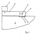
- the waveguide 3 is arranged between the magentron 1 generating the microwaves and the cooking chamber 2.
- the rotating body 5 In front of the rear wall 4 of the end of the waveguide 3 facing away from the magnetron, the rotating body 5 is arranged, which consists of a plate running parallel to the rear wall and rotatable about its central longitudinal axis.
- the wave resistance of the magnetron 1 through the waveguide 3 via the coupling opening 6 into the cooking space can be changed periodically by the rotating body 5.
- This change in the input resistance of the furnace affects the magnetron 1 by periodically changing its output frequency.
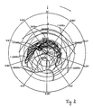
- the change at an output frequency of 2.450 GHz can be up to ⁇ 10 MHz, which results in a superposition of different resonance forms. This leads to an even heating of the food.
- the effect of the device according to the invention is not based on the deflection of the microwaves by a complicated "wave stirrer", but on the "change in length" of the waveguide, which couples the microwaves into the cooking space. This is done by a simple sheet metal part. While the waveguide is shortened in the position of the plate of the rotating body shown, this plate is practically ineffective in the dashed position. When the plate rotates in the direction of the arrow, the wave resistance changes constantly and periodically.
- the coupling opening 6 is covered in a known manner by a wall 7 which is permeable to microwaves and which prevents harmful influences from acting on the magnetron from the cooking space. High-temperature resistant dielectric materials such as ceramics or borosilicate glass are common for this.
- the rotating body 5 has a good effect if it is located at a distance between ⁇ / 4 and ⁇ / 2 from the rear wall 4 and above the coupling opening 6.
Landscapes
- Physics & Mathematics (AREA)
- Electromagnetism (AREA)
- Engineering & Computer Science (AREA)
- Power Engineering (AREA)
- Constitution Of High-Frequency Heating (AREA)
- Electric Ovens (AREA)
- General Preparation And Processing Of Foods (AREA)
Abstract
Description
Die Erfindung betrifft ein Verfahren zur Vergleichmäßigung der Erwärmung von Speisen in einem mit Mikrowellenenergie beheizten Gargerät und eine Vorrichtung zur Durchführung dieses Verfahrens.The invention relates to a method for equalizing the heating of food in a microwave oven heated cooking device and an apparatus for performing this method.
Bei einem Mikrowellenofen werden in einen als Resonanzkammer wirkenden Garraum, welcher von den metallischen Wänden der Garmuffel umschlossen wird, die von einem Magnetron erzeugten Mikrowellen eingespeist. Es ist dabei möglich die Ausgangssonde des Magnetrons unmittelbar in den Garraum zu führen. Zur Verbesserung der Gleichförmigkeit der Erwärmung des Gargutes ist es bereits bekannt sogenannte Drehantennen vorzusehen, welche das Mikrowellenfeld relativ zum ruhenden Gargut bewegen. Abgesehen davon, daß die direkte Einspeisung der Mikrowellen in den Garraum große Anpassungsschwierigkeiten des Magnetrons an unterschiedliche Beschickung des Garraumes mit sich bringt, ist eine solche Konstruktion sehr aufwendig. Auch verbleibt wegen der unterschiedlichen Resonanzstruktur des Garraumes eine Umgleichmäßigkeit der Erwärmung.In a microwave oven, the microwaves generated by a magnetron are fed into a cooking chamber which acts as a resonance chamber and which is enclosed by the metallic walls of the cooking muffle. It is possible to feed the magnetron output probe directly into the cooking space. In order to improve the uniformity of the heating of the food to be cooked, it is already known to provide so-called rotating antennas which move the microwave field relative to the food at rest. In addition to the fact that the direct feeding of the microwaves into the cooking space entails great difficulties in adapting the magnetron to different loads in the cooking space, such a construction is very complex. Because of the different resonance structure of the cooking chamber, the heating remains uneven.
Es ist heute allgemein üblich, die Antennensonde des Magnetrons in eine Wellenleitung einzusetzen, wobei die Antennensonde im Abstand von einem Viertel der Wellenlänge von einem kurzgeschlossenen Ende der Wellenleitung eingesetzt ist, so daß möglichst die gesamte Mikrowellenenergie in die andere Richtung ausgekoppelt wird. Das dem kurzgeschlossenen Ende der Wellenleitung gegenüberliegende Ende mündet im allgemeinen über eine Einkopplungsöffnung zwischen Wellenleiter und Garraum in der Garmuffel. Zur Vergleichmäßigung der Erwärmung ist es dabei üblich, in der Nähe der Einflopplungsöffnung einen sogenannten "Wellenrührer" anzuordnen. Die DE-PS 26 22 363 zeigt einen solchen Wellenrührer, dess Rührflügel unter dem Magnetron aber über dem Garraum angeordnet und vom Garraum durch eine Wand getrennt sind. Eine ähnliche Ausführung zeigt die DE-OS 29 21 266 in Fig. 2. Die Wellenrührer haben die Aufgabe mit ihren sich drehenden Flügeln die Mikrowellen unterschieldich zu reflektieren und so ein Streufeld in den Garraum einzuspeisen. Auch solche Konstruktionen sind aufwendig, ebenso wie die bekannten Drehteller, bei denen das Gargut in dem Garraum stetig bewegt wird, um eine gleichmäßige Erwärmung zu erzielen.It is common today to insert the antenna probe of the magnetron into a waveguide, the antenna probe being inserted at a distance of a quarter of the wavelength from a short-circuited end of the waveguide, so that as much of the microwave energy as possible is coupled out in the other direction. The end opposite the short-circuited end of the waveguide generally opens into the cooking muffle via a coupling opening between the waveguide and the cooking space. To make the heating more uniform, it is customary to arrange a so-called “wave stirrer” near the inflow opening. DE-PS 26 22 363 shows such a wave stirrer, the stirring blades of which are arranged under the magnetron but above the cooking space and are separated from the cooking space by a wall. A similar version is shown in DE-OS 29 21 266 in Fig. 2. The wave stirrers have the task of reflecting the microwaves with their rotating blades and thus feeding a stray field into the cooking space. Such constructions are also complex, as are the known turntables, in which the food to be cooked is constantly moved in the cooking space in order to achieve uniform heating.
Der Erfindung liegt die Aufgabe zugrunde, den Nachteil von Mikrowellenöfen, daß nämlich das Erwärmungsgut aufgrund einer ungleichmäßigen Feldverteilung inhomogen erwärmt wird, durch eine einfche Maßnahme zu beheben.The object of the invention is to remedy the disadvantage of microwave ovens, namely that the material to be heated is inhomogeneously heated due to an uneven field distribution, by a simple measure.
Zur Lösung dieser Aufgabe wird die an sich unerwünschte Änderung der Belastungsimpedanz des Magnetrons bei unterschiedlicher Beschicksbedingung dazu benutzt, eine Frequenzänderung des Magnetrons herbeizuführen und dadurch eine gleichmäßige Erwärmung des Gargutes zu erzielen.To solve this problem, the undesirable change in the load impedance of the magnetron under different loading conditions is used to bring about a change in frequency of the magnetron and thereby achieve a uniform heating of the food.
Im Patentanspruch 1 sind die zur Lösung der Aufgabe dienenden Merkmale angegeben.In
Durch die periodische Veränderung des Wellenwiderstandes ergibt sich eine periodische Veränderung der Ausgangsfrequenz des Magnetrons und diese Frequenzänderung bewirkt in dem als Resonator dienenden Garraum die Anregung unterschiedlicher Resonanzformen. Die Überlagerung verschiedener Resonanzformen führt zu einem in der Summe gleichmäßigen Erwärmungsergebnis.The periodic change in the wave resistance results in a periodic change in the output frequency of the magnetron and this change in frequency causes the excitation of different forms of resonance in the cooking chamber serving as a resonator. The superimposition of different resonance forms leads to an overall uniform heating result.
In der Zeichnung ist ein Ausführungsbeispiel der Erfindung dargestellt. Es zeigen:
- Fig. 1 schematisch die Vorrichtung zur Mikrowelleneinspeisung
- Fig. 2 den periodischen Verlauf der Eingangsimpedanz eines Mikrowellenofens im Smith-Diagramm.
- Fig. 1 shows schematically the device for microwave feeding
- Fig. 2 shows the periodic course of the input impedance of a microwave oven in the Smith chart.
Zwischen dem die Mikrowellen erzeugenden Magentron 1 und dem Garraum 2 ist der Hohlleiter 3 angeordnet. Vor der Ruckwand 4 des dem Magnetron abgewandten Ende des Hohlleiters 3 ist der Drehkörper 5 angeordnet, welcher aus einer parallel zur Rückwand verlaufenden und um seine Mittelängsachse drehbaren Platte besteht. Der Wellenwiderstand der vom Magnetron 1 durch den Hohlleiter 3 über die Einkopplungsöffnung 6 in den Garraum kann durch den Drehkörper 5 periodisch verändert werden. Diese Änderung des Eingangswiderstandes des Ofens wirkt auf des Magnetron 1 zurück indem dessen Ausgangsfrequenz periodisch verändert wird. Wie aus dem Diagramm nach Fig. 2 zu entnehmen ist, kann die Änderung bei einer Ausgangsfrequenz von 2,450 GHz bis zu ± 10 MHz betragen, wodurch sich eine Überlagerung verschiedener Resonanzformen ergibt. Dies führt zu einer gleichmäßigen Erwärmung des Gargutes. Die Wirkung der erfindungsgemäßen Vorrichtung beruht nicht auf der Umlenkung der Mikrowellen durch einen komplizierten "Wellenrührer", sondern durch die "Längenänderung" des Hohlleiters, der die Mikrowellen in den Garraum einkoppelt. Diese erfolgt durch ein einfaches Blechteil. Während in der gezeigten Stellung der Platte des Drehkörpers der Hohlleiter verkürzt ist, ist in der gestrichelten Stellung diese Platte praktisch nicht wirksam. Bei Drehung der Platte in Pfeilrichtung ändert sich somit ständig und periodisch der Wellenwiderstand. Die Einkopplungsöffnung 6 ist in bekannter Weise durch eine für Mikrowellen durchlässige Wand 7 abgedeckt, welche verhindert, daß aus dem Garraum schädliche Einflüsse auf das Magnetron einwirken können. Üblich sind hierfür hochtemperaturbeständige dielektrische Materialien wie Keramik oder Borsilikatglas.The
Eine gute Wirkung des Drehkörpers 5 ist gegeben, wenn er sich im Abstand zwischen λ/4 und λ/2 von der Rückwand 4 und oberhalb der Einkopplungsöffnung 6 befindet.The rotating
Claims (7)
dadurch gekennzeichnet, daß sich von der Rückwand (4) des Hohlleiters (3) eine die Rückwand veränderlich abschirmender Drehkörper (5) befindet.2. Apparatus for carrying out the method according to claim 1, in a microwave oven with an elongated waveguide leading from the micro energy source to the cooking space, which ends at its end facing away from the microwave generator with a rear wall arranged perpendicular to a coupling opening between the waveguide and the cooking space
characterized in that there is a rotating body (5) which shields the rear wall in a variable manner from the rear wall (4) of the waveguide (3).
dadurch gekennzeichnet, daß der Drehkörper (5) aus einer um seine Mittellängsachse drehbaren Platte besteht.3. Device according to claim 2
characterized in that the rotating body (5) consists of a plate rotatable about its central longitudinal axis.
dadurch gekennzeichnet, daß der Drehkörper (5) im Abstand λ/4 bis λ/2 vor der Rückwand (4) angeordnet ist.5. The device according to claim 2 and / or 3rd
characterized in that the rotating body (5) is arranged at a distance λ / 4 to λ / 2 in front of the rear wall (4).
dadurch gekennzeichnet, daß der Drehkörper etwa im Abstand 3λ/8 vor der Rückwand (4) angeordnet ist.Device according to one of claims 2 to 4
characterized in that the rotating body is arranged approximately at a distance of 3λ / 8 in front of the rear wall (4).
dadurch gekennzeichnet, daß sich die sich die Einkopplungsöffnung (6) unterhalb des Drehkörpers (5) befindet.6. Device according to one of claims 2 to 5
characterized in that the coupling opening (6) is located below the rotating body (5).
dadurch gekennzeichnet, daß eine Änderung der Ausgangsfrequenz von 2,450 GHz auf ± 10 MHz erfolgt.7. Device according to one of claims 2 to 6
characterized in that the output frequency changes from 2.450 GHz to ± 10 MHz.
Priority Applications (1)
| Application Number | Priority Date | Filing Date | Title |
|---|---|---|---|
| AT87118985T ATE91375T1 (en) | 1987-02-03 | 1987-12-21 | METHOD AND APPARATUS FOR EQUALIZING THE HEATING OF FOOD IN A MICROWAVE ENERGY HEATED COOKING APPLIANCE. |
Applications Claiming Priority (2)
| Application Number | Priority Date | Filing Date | Title |
|---|---|---|---|
| DE3703133 | 1987-02-03 | ||
| DE19873703133 DE3703133A1 (en) | 1987-02-03 | 1987-02-03 | METHOD AND DEVICE FOR COMPARISONING THE HEATING OF FOOD IN A COOKER HEATED WITH MICROWAVE ENERGY |
Publications (3)
| Publication Number | Publication Date |
|---|---|
| EP0277342A2 true EP0277342A2 (en) | 1988-08-10 |
| EP0277342A3 EP0277342A3 (en) | 1988-08-31 |
| EP0277342B1 EP0277342B1 (en) | 1993-07-07 |
Family
ID=6320098
Family Applications (1)
| Application Number | Title | Priority Date | Filing Date |
|---|---|---|---|
| EP87118985A Expired - Lifetime EP0277342B1 (en) | 1987-02-03 | 1987-12-21 | Method and device to homogenize the heating of food in a cooking oven heated by microwaves |
Country Status (3)
| Country | Link |
|---|---|
| EP (1) | EP0277342B1 (en) |
| AT (1) | ATE91375T1 (en) |
| DE (2) | DE3703133A1 (en) |
Cited By (3)
| Publication number | Priority date | Publication date | Assignee | Title |
|---|---|---|---|---|
| EP0344438A1 (en) * | 1988-05-31 | 1989-12-06 | Bosch-Siemens HausgerÀ¤te GmbH | Microwave household appliance |
| WO1997047161A3 (en) * | 1996-06-03 | 1998-02-05 | Matsushita Electric Industrial Co Ltd | Microwave heating apparatus |
| EP2187702A1 (en) * | 2008-11-17 | 2010-05-19 | Topinox Sarl | Cooking device with microwave heating |
Families Citing this family (1)
| Publication number | Priority date | Publication date | Assignee | Title |
|---|---|---|---|---|
| DE3843039A1 (en) * | 1988-12-21 | 1990-06-28 | Bosch Siemens Hausgeraete | HOUSEHOLD APPLIANCE |
Family Cites Families (8)
| Publication number | Priority date | Publication date | Assignee | Title |
|---|---|---|---|---|
| US2761942A (en) * | 1952-06-06 | 1956-09-04 | Raytheon Mfg Co | Heating apparatus |
| GB752206A (en) * | 1953-11-12 | 1956-07-04 | Raytheon Mfg Co | Improvements in or relating to high frequency dielectric heating apparatus |
| FR1208182A (en) * | 1957-12-10 | 1960-02-22 | Miwag Mikrowellen A G | Device for generating a defined primary field distribution in a cavity for heating organic substances by means of microwave frequencies |
| CH393577A (en) * | 1961-12-13 | 1965-06-15 | Patelhold Patentverwertung | Device for dielectric heating of materials |
| US3521019A (en) * | 1968-02-19 | 1970-07-21 | Varian Associates | Microwave heating cavity with a venetian blind mode stirrer |
| SE345903B (en) * | 1970-12-21 | 1972-06-12 | Philips Svenska Ab | |
| US4301347A (en) * | 1980-08-14 | 1981-11-17 | General Electric Company | Feed system for microwave oven |
| US4336434A (en) * | 1980-08-15 | 1982-06-22 | General Electric Company | Microwave oven cavity excitation system employing circularly polarized beam steering for uniformity of energy distribution and improved impedance matching |
-
1987
- 1987-02-03 DE DE19873703133 patent/DE3703133A1/en not_active Withdrawn
- 1987-12-21 AT AT87118985T patent/ATE91375T1/en active
- 1987-12-21 DE DE8787118985T patent/DE3786451D1/en not_active Expired - Fee Related
- 1987-12-21 EP EP87118985A patent/EP0277342B1/en not_active Expired - Lifetime
Cited By (4)
| Publication number | Priority date | Publication date | Assignee | Title |
|---|---|---|---|---|
| EP0344438A1 (en) * | 1988-05-31 | 1989-12-06 | Bosch-Siemens HausgerÀ¤te GmbH | Microwave household appliance |
| WO1997047161A3 (en) * | 1996-06-03 | 1998-02-05 | Matsushita Electric Industrial Co Ltd | Microwave heating apparatus |
| US6114677A (en) * | 1996-06-03 | 2000-09-05 | Matsushita Electric Industrial Co., Ltd. | Microwave heating apparatus having a metal plate rotatably disposed in a wave guide |
| EP2187702A1 (en) * | 2008-11-17 | 2010-05-19 | Topinox Sarl | Cooking device with microwave heating |
Also Published As
| Publication number | Publication date |
|---|---|
| DE3786451D1 (en) | 1993-08-12 |
| DE3703133A1 (en) | 1988-08-11 |
| ATE91375T1 (en) | 1993-07-15 |
| EP0277342A3 (en) | 1988-08-31 |
| EP0277342B1 (en) | 1993-07-07 |
Similar Documents
| Publication | Publication Date | Title |
|---|---|---|
| DE2622173C3 (en) | Device for heating an object placed in a heating chamber | |
| DE2504860C3 (en) | ||
| DE2650681C3 (en) | Microwave oven | |
| DE69106825T2 (en) | Microwave oven, a method for excitation of an oven cavity, and a waveguide arrangement for carrying out the method. | |
| DE2516622C3 (en) | Microwave oven | |
| DE2432488A1 (en) | DEVICE FOR SUPPORTING ARTICLES TO BE TREATED WITH MICROWAVE ENERGY, IN PARTICULAR FOOD TO BE HEATED IN A MICROWAVE OVEN | |
| DE3310703A1 (en) | MICROWAVE COOKER | |
| DE2058901C3 (en) | High frequency heater | |
| DE112015000981T5 (en) | Microwave treatment device | |
| DE2232065C3 (en) | Microwave heating device | |
| EP0277342B1 (en) | Method and device to homogenize the heating of food in a cooking oven heated by microwaves | |
| DE3308732A1 (en) | HIGH FREQUENCY HEATING UNIT WITH A ROTATING ANTENNA | |
| EP0285020A2 (en) | Arrangement for coupling microwave energy to a leaky microwave line | |
| DE1051337B (en) | Traveling field pipes with a helix as a delay line | |
| DE2417577C2 (en) | High-frequency heating device for heating a dielectric material of elongated shape and small cross-section | |
| DE3331432A1 (en) | HIGH FREQUENCY HEATER | |
| DE3818490C2 (en) | ||
| DE69408022T2 (en) | Device with a large aperture to monitor the thickness of a conductive coating on optical fibers | |
| DE102017100074B4 (en) | Process for treating food and cooking appliance for carrying out such a process | |
| DE1523101A1 (en) | Microwave cavity resonator | |
| DE3138027C2 (en) | ||
| DE2636633C3 (en) | Delay line for traveling wave tubes, especially for amplifying mm waves | |
| DE1615463C3 (en) | Oven with radiation of microwave energy and with a resistance heated metal element | |
| EP0049817A1 (en) | Microwave heating apparatus with door sealing for preventing leakage of microwaves | |
| DE1565259C3 (en) |
Legal Events
| Date | Code | Title | Description |
|---|---|---|---|
| PUAI | Public reference made under article 153(3) epc to a published international application that has entered the european phase |
Free format text: ORIGINAL CODE: 0009012 |
|
| PUAL | Search report despatched |
Free format text: ORIGINAL CODE: 0009013 |
|
| AK | Designated contracting states |
Kind code of ref document: A2 Designated state(s): AT BE CH DE FR GB IT LI NL |
|
| AK | Designated contracting states |
Kind code of ref document: A3 Designated state(s): AT BE CH DE FR GB IT LI NL |
|
| 17P | Request for examination filed |
Effective date: 19881010 |
|
| 17Q | First examination report despatched |
Effective date: 19910208 |
|
| RAP1 | Party data changed (applicant data changed or rights of an application transferred) |
Owner name: ELECTROLUX-JUNO KUECHENTECHNIK GMBH |
|
| GRAA | (expected) grant |
Free format text: ORIGINAL CODE: 0009210 |
|
| AK | Designated contracting states |
Kind code of ref document: B1 Designated state(s): AT BE CH DE FR GB IT LI NL |
|
| PG25 | Lapsed in a contracting state [announced via postgrant information from national office to epo] |
Ref country code: NL Effective date: 19930707 Ref country code: BE Effective date: 19930707 |
|
| REF | Corresponds to: |
Ref document number: 91375 Country of ref document: AT Date of ref document: 19930715 Kind code of ref document: T |
|
| REF | Corresponds to: |
Ref document number: 3786451 Country of ref document: DE Date of ref document: 19930812 |
|
| ET | Fr: translation filed | ||
| GBT | Gb: translation of ep patent filed (gb section 77(6)(a)/1977) |
Effective date: 19930728 |
|
| ITF | It: translation for a ep patent filed | ||
| PGFP | Annual fee paid to national office [announced via postgrant information from national office to epo] |
Ref country code: GB Payment date: 19931206 Year of fee payment: 7 |
|
| NLV1 | Nl: lapsed or annulled due to failure to fulfill the requirements of art. 29p and 29m of the patents act | ||
| PGFP | Annual fee paid to national office [announced via postgrant information from national office to epo] |
Ref country code: FR Payment date: 19931217 Year of fee payment: 7 |
|
| PG25 | Lapsed in a contracting state [announced via postgrant information from national office to epo] |
Ref country code: AT Effective date: 19931221 |
|
| PG25 | Lapsed in a contracting state [announced via postgrant information from national office to epo] |
Ref country code: LI Effective date: 19931231 Ref country code: CH Effective date: 19931231 |
|
| PGFP | Annual fee paid to national office [announced via postgrant information from national office to epo] |
Ref country code: DE Payment date: 19940225 Year of fee payment: 7 |
|
| PLBE | No opposition filed within time limit |
Free format text: ORIGINAL CODE: 0009261 |
|
| STAA | Information on the status of an ep patent application or granted ep patent |
Free format text: STATUS: NO OPPOSITION FILED WITHIN TIME LIMIT |
|
| 26N | No opposition filed | ||
| REG | Reference to a national code |
Ref country code: CH Ref legal event code: PL |
|
| PG25 | Lapsed in a contracting state [announced via postgrant information from national office to epo] |
Ref country code: GB Effective date: 19941221 |
|
| GBPC | Gb: european patent ceased through non-payment of renewal fee |
Effective date: 19941221 |
|
| PG25 | Lapsed in a contracting state [announced via postgrant information from national office to epo] |
Ref country code: FR Effective date: 19950831 |
|
| PG25 | Lapsed in a contracting state [announced via postgrant information from national office to epo] |
Ref country code: DE Effective date: 19950901 |
|
| REG | Reference to a national code |
Ref country code: FR Ref legal event code: ST |
|
| PG25 | Lapsed in a contracting state [announced via postgrant information from national office to epo] |
Ref country code: IT Free format text: LAPSE BECAUSE OF NON-PAYMENT OF DUE FEES;WARNING: LAPSES OF ITALIAN PATENTS WITH EFFECTIVE DATE BEFORE 2007 MAY HAVE OCCURRED AT ANY TIME BEFORE 2007. THE CORRECT EFFECTIVE DATE MAY BE DIFFERENT FROM THE ONE RECORDED. Effective date: 20051221 |