EP0276761A2 - Latch device for inclinable back rest cushion mounted in seatback - Google Patents
Latch device for inclinable back rest cushion mounted in seatback Download PDFInfo
- Publication number
- EP0276761A2 EP0276761A2 EP19880100872 EP88100872A EP0276761A2 EP 0276761 A2 EP0276761 A2 EP 0276761A2 EP 19880100872 EP19880100872 EP 19880100872 EP 88100872 A EP88100872 A EP 88100872A EP 0276761 A2 EP0276761 A2 EP 0276761A2
- Authority
- EP
- European Patent Office
- Prior art keywords
- latch device
- back rest
- latch
- rest cushion
- cushion
- Prior art date
- Legal status (The legal status is an assumption and is not a legal conclusion. Google has not performed a legal analysis and makes no representation as to the accuracy of the status listed.)
- Granted
Links
Images


Classifications
-
- B—PERFORMING OPERATIONS; TRANSPORTING
- B60—VEHICLES IN GENERAL
- B60N—SEATS SPECIALLY ADAPTED FOR VEHICLES; VEHICLE PASSENGER ACCOMMODATION NOT OTHERWISE PROVIDED FOR
- B60N2/00—Seats specially adapted for vehicles; Arrangement or mounting of seats in vehicles
- B60N2/24—Seats specially adapted for vehicles; Arrangement or mounting of seats in vehicles for particular purposes or particular vehicles
- B60N2/32—Seats specially adapted for vehicles; Arrangement or mounting of seats in vehicles for particular purposes or particular vehicles convertible for other use
- B60N2/36—Seats specially adapted for vehicles; Arrangement or mounting of seats in vehicles for particular purposes or particular vehicles convertible for other use into a loading platform
- B60N2/366—Seats specially adapted for vehicles; Arrangement or mounting of seats in vehicles for particular purposes or particular vehicles convertible for other use into a loading platform characterised by the locking device
-
- B—PERFORMING OPERATIONS; TRANSPORTING
- B60—VEHICLES IN GENERAL
- B60N—SEATS SPECIALLY ADAPTED FOR VEHICLES; VEHICLE PASSENGER ACCOMMODATION NOT OTHERWISE PROVIDED FOR
- B60N2205/00—General mechanical or structural details
- B60N2205/30—Seat or seat parts characterised by comprising plural parts or pieces
- B60N2205/35—Seat, bench or back-rests being split laterally in two or more parts
-
- Y—GENERAL TAGGING OF NEW TECHNOLOGICAL DEVELOPMENTS; GENERAL TAGGING OF CROSS-SECTIONAL TECHNOLOGIES SPANNING OVER SEVERAL SECTIONS OF THE IPC; TECHNICAL SUBJECTS COVERED BY FORMER USPC CROSS-REFERENCE ART COLLECTIONS [XRACs] AND DIGESTS
- Y10—TECHNICAL SUBJECTS COVERED BY FORMER USPC
- Y10T—TECHNICAL SUBJECTS COVERED BY FORMER US CLASSIFICATION
- Y10T292/00—Closure fasteners
- Y10T292/08—Bolts
- Y10T292/0911—Hooked end
- Y10T292/0926—Spring projected
- Y10T292/0928—Operating means
- Y10T292/0932—Lever
-
- Y—GENERAL TAGGING OF NEW TECHNOLOGICAL DEVELOPMENTS; GENERAL TAGGING OF CROSS-SECTIONAL TECHNOLOGIES SPANNING OVER SEVERAL SECTIONS OF THE IPC; TECHNICAL SUBJECTS COVERED BY FORMER USPC CROSS-REFERENCE ART COLLECTIONS [XRACs] AND DIGESTS
- Y10—TECHNICAL SUBJECTS COVERED BY FORMER USPC
- Y10T—TECHNICAL SUBJECTS COVERED BY FORMER US CLASSIFICATION
- Y10T292/00—Closure fasteners
- Y10T292/08—Bolts
- Y10T292/0911—Hooked end
- Y10T292/0926—Spring projected
- Y10T292/0928—Operating means
- Y10T292/0933—Push or pull rod
-
- Y—GENERAL TAGGING OF NEW TECHNOLOGICAL DEVELOPMENTS; GENERAL TAGGING OF CROSS-SECTIONAL TECHNOLOGIES SPANNING OVER SEVERAL SECTIONS OF THE IPC; TECHNICAL SUBJECTS COVERED BY FORMER USPC CROSS-REFERENCE ART COLLECTIONS [XRACs] AND DIGESTS
- Y10—TECHNICAL SUBJECTS COVERED BY FORMER USPC
- Y10T—TECHNICAL SUBJECTS COVERED BY FORMER US CLASSIFICATION
- Y10T292/00—Closure fasteners
- Y10T292/08—Bolts
- Y10T292/1043—Swinging
- Y10T292/1075—Operating means
Definitions
- the present invention relates in general to latch devices, and particularly to latch devices of a type which latches a pivotal member. More specifically, the present invention is concerned with a latch device for latching an inclinable back rest cushion which is pivotally mounted in a rear seat seatback of a passenger motor vehicle to provide, when folded, a tunnel between a passenger room and a trunk room.
- a striker is fixed to a vehicle body, and a hook engageable with the striker is mounted to the inclinable back rest.
- a push button is mounted on the back rest to actuate the hook.
- a pull strap extends from the push button and is exposed to the passenger room. When the pull strap is pulled from the passenger room, the push button is moved and thus the hook is actuated to release the engagement with the striker.
- a latch slider operable from the trunk room is incorporated with the push button to disable the same from moving. Once the latch slider assumes its operative position, the push button does not move even when the pull strap is pulled. Thus, under this, the latched engagement between the hook and the striker is not released.
- a striker is fixed to an inclinable back rest, and a hook is mounted to a vehicle body.
- a handle member is pivotally mounted on the vehicle body to actuate the hook.
- An operation lever operable from a trunk room is incorporated with the handle member.
- a connecting member is incorporated with the handle member and actuated by the operation lever.
- a latch device for latching the back rest cushion to the seatback when the cushion is snugly receieved in the tunnel.
- the latch device comprises a striker secured to the seatback; a latch member pivotally mounted in the back rest cushion in a manner to latchingly engage with the striker upon the cushion being received in the tunnel; first biasing means for biasing the latch member in a direction to achieve the latched engagement between the latch member and the striker; an actuation member pivotally mounted in the back rest cushion in a manner to push and pivot the latch member in a releasing direction to cancel the latched engagement between the latch member and the striker when pivoted in a given direction; second means having a pin portion which is projectable into a travelling way of the actuation member thereby to interrupt the actuation member from pivoting in the releasing direction; a base member secured to a rigid portion of the back rest cushion and having an opening through
- Figs. 1 to 8 show a first embodiment of the present invention.
- an automotive rear seat which comprises a seat cushion and a seatback 10.
- the seatback 10 is equipped with an inclinable back rest cushion 11.
- the cushion 11 is usually received in a tunnel "T" formed in the seatback 10.
- the tunnel "T” is exposed to connect a passenger room "B” with a trunk room "A".
- a known hinge device is arranged between a rear end of the seat cushion and a lower portion of the back rest cushion 11 to achieve a pivotal movement of the cushion 10 relative to the seatback 10.
- a latch device 20A of the first embodiment is mounted to the inclinable back rest cushion 11 to move therewith. As is seen from Fig. 2, the latch device 20A is substantially entirely installed in the back rest cushion 11. Designated by numeral 11a is a slot which is formed in the back side of the back rest cushion 11 for receiving therein a striker 15 upon raising of the cushion 11.
- the latch device 20A comprises a base member 21 which is secured to a rigid frame member (not shown) installed in a free upper portion 12 (see Fig. 2) of the back rest cushion 11.
- the base member 21 has a raised center portion 21b for housing therein a bumper rubber piece 21a. It is to be noted that the parts shown in Fig. 1 are so oriented that the left side of the drawing faces the passenger room "B" and the right side faces the trunk room "A”.
- the raised . center portion 21b is formed with a semicircular cut 21c through which the bumper rubber piece 21a is exposed.
- the striker 15 Upon raising of the back rest cushion 11, the striker 15 abuts against the rubber piece 21a to bump the movement of the cushion 11.
- a pivot shaft 22 is fixed to the raised center portion 21b of the base member 21, which extends upward therefrom.
- a latch member 30 is pivotally disposed about the pivot shaft 22. As will be described in detail hereinafter, the latch member 30 is latchingly engageable with the striker 15 which is secured to a wall of the tunnel "T" (see Fig. 2). For this, the latch member 30 is arranged to be exposed to the slot 11a of the back rest cushion 11.
- the latch member 30 is formed with a raised flange 31 having a bent end 31a.
- a coil spring 23 is disposed about the pivot shaft 22 having one end hooked to the raised flange 31 of the latch member 30 and the other end hooked to the pivot shaft 22. With this spring 23, the latch member 30 is biased to rotate in a clockwise direction in Fig. 3, that is, in a direction to achieve latched engagement with the striker 15.
- An actuation member 60 is also pivotally disposed about the pivot shaft 22 at a position between the base member 21 and the latch member 30.
- the actuation member 60 is formed with an upwardly extending portion 61 and a downwardly extending portion 62. As is seen from Fig. 1, upon assembly, the upwardly extending portion 61 is placed behind the raised flange 31 of the latch member 30. A top of the upwardly extending portion 61 is bent to form a flat portion 63 to which a pull strap 70 is connected through a screw 71.
- the pull strap 70 is so sized that upon the inclinable back rest cushion 11 assuming its raised latched position, at least a portion of the strap 70 is exposed to the passenger room "B" to be manipulated by a seat occupant.
- the interfering mechanism comprises a stopper pin 50 which slidably passes through an opening 24 formed in the base member 21.
- the opening 24 is so positioned that when the stopper pin 50 assumes its raised or upper position, it intersects the travelling way of the downwardly extending portion 62 of the actuation member 60 for the reason which will be clarified as the description proceeds.
- the stopper pin 50 has a reduced head portion 51 and a bent lower portion 52.
- an actuation mechanism is incorporated with the stopper pin 50.
- the actuation mechanism comprises a pivoting lever 42 which is pivotally connected through a pivot pin 42a to a guide bracket 41.
- the guide bracket 41 is secured to a rigid member (not shown) of the inclinable back rest cushion 11.
- the bracket 41 has an arm which has an opening 41b through which a major portion of the stopper pin 50 slidably passes.
- the pivoting lever 42 has one arm part 43 which has an opening (no numeral) into which the bent lower portion 52 of the stopper pin 50 is slidably inserted to achieve a pivotal connection therebetween and the other arm part 44 which has an opening (no numeral) to which a bent upper end 45 of an elongate rod 46 is pivotally connected through a known clip (no numeral).
- a turn over spring 41a is disposed between the pivoting lever 42 and the guide bracket 41 in order to make a turn over action of the pivoting lever 42. That is, when a pivoting movement of the poviting lever 42 in one direction goes beyond a predetermined angule, the movement is violently accelerated by the spring 41a in a snap action manner.
- the elongate rod 46 extends downward toward a base plate 48 which is secured to another rigid structure of the inclinable back rest cushion 11.
- the base plate 48 has an elongate slot 48a through which a bent lower end 47 of the rod 46 is projected into the outside of the back rest cushion 11.
- a control knob 40 is fixed to the outwardly projected part of the bent lower end 47.
- a rod holder 49 is fixed to the base plate 48 to slidably hold the rod 46.
- the control knob 40 assumes either one of the uppermost and lowermost positions defined by the elongate slot 48a of the base plate 48. As is understood from Fig.
- the pull strap 70 When, for the purpose of inclining the back rest cushion 11, the pull strap 70 is pulled from the passenger room "B", the actuation member 60 is pivoted in a given direction (viz., in a counterclockwise direction in Fig. 1) pushing at the upwardly extending portion 61 thereof the bent end 31a of the latch member 30 in the same direction against the biasing force of the coil spring 23. With this, the latch member 30 is disengaged from the striker 15. Thus, further pulling of the strap 70 induces a foward inclination of the back rest cushion 11 as shown in Fig. 2.
- the cushion 11 When, for receiving the cushion 11 into the tunnel “T”, the cushion 11 is raised and thrusted into the tunnel “T”, the striker 15 is inserted into the slot 11a of the cushion 11 (see Fig. 2) and brought into contact with a curved head 30a of the latch member 30 (see Fig. 1). Pushing the cushion 11 with a certain force causes the striker 15 to push the head 30a of the latch member 30 away against the biasing force of the spring 23 and thereafter become latched by the latch member 30 by the work of the spring 23. With this, the cushion 11 assumes the above-mentioned original latched position.
- Figs. 9 to 11 show a second embodiment of the present invention.
- a latch device 20B of the second embodiment there are no members which correspond to the stopper pin 50 and the pivoting lever 42 of the first embodiment.
- the latch device 20B comprises a base member 85 which is secured to a rigid frame member (not shown) installed in a free upper portion 12 (see Fig. 2) of the back rest cushion 11. It is to be noted that the parts shown in Fig. 9 are so oriented that the left side of the drawing faces the passenger room "B" and the right side faces the trunk room "A".
- the base member 85 has a raised center portion (no numeral) for housing therein a bumper rubber piece 21a.
- the raised center portion is formed with a semicircular cut through which the bumper rubber piece 21a is exposed.
- the base member 85 is formed with a generally U-shaped lower portion 85a, and aligned openings 86 and 87 are formed in opposed walls of the portion 85a.
- a guide plate 90 having an L-shaped cross section is bolted to the base member 85 in such a manner that an upper flat portion 90a thereof is attached to a lower side of the base member 85.
- the upper flat portion 90a is formed with an opening 91 which is mated with the opening 87 of the base member 85.
- the other flat portion 90b of the guide plate 90 is tightly bolted to the frame member of the back rest cushion 11.
- a pivot shaft 22 is fixed to the raised center portion of the base member 85, which extends upward therefrom.
- a latch member 30 is pivotally disposed about the pivot shaft 22.
- the latch member 30 is formed with a raised flange 31 having a bent end 31a.
- a coil spring 23 is disposed about the pivot shaft 22 having one end hooked to the raised flange 31 of the latch member 30 and the other end hooked to the pivot shaft 22.
- the latch member 30 is biased to rotate in a clockwise direction in Fig. 9, that is, in a direction to achieve latched engagement with the striker 15.
- An actuation member 97 is also pivotally disposed about the pivot shaft 22 at a position between the base member 85 and the latch member 30.
- the actuation member 97 is formed with an upwardly extending portion 99 and a downwardly extending portion 98.
- the upwardly extending portion 99 is placed behind the raised flange 31 of the latch member 30.
- a top of the upwardly extending portion 99 is bent to form a flat portion to which a pull strap 70 is connected through a screw 71.
- the bent end 31a of the latch member 30 abuts on the upwardly extending portion 99 of the actuation member 97 thereby to bias the same in a clockwise direction in Fig. 9.
- the interfering mechanism comprises a stopper rod 80 which slidably passes through the opening 86 of the base member 86, the opening 91 of the guide plate 90 and the opening 87 of the base member 85.
- the openings 86, 91 and 87 are so positioned that when the rod 80 assumes its raised or upper position, it intersects the travelling way of the downwardly extending portion 98 of the actuation member 97.
- the stopper rod 80 has a straight upper portion 82 and a bent lower portion 81.
- the stopper rod 80 is axially slidably connected through clips 49 and 49 to a plate member 95 which is secured to the back rest cushion 11.
- the plate member 95 is formed with an elongate slot 95a through which the bent lower portion 81 of the rod 80 is projected into the outside of the back rest cushion 11.
- a control knob 40 is fixed to the outwardly projected part of the bent lower portion 81.
- a turn over spring 41a is disposed between the rod 80 and the plate member 95 in order to make a turn over action of the stopper rod 80.
- the control knob 40 assumes either one of the uppermost and lowermost positions defined by the elongate slot 95a of the plate member 95. As is understood from Fig.
- the stopper rod 80 assumes its upper or operative position, that is, the position to interfere the pivotal movement of the actuation member 97, while, when the control knob 40 assumes the lowermost position as illustrated by a phantom line, the stopper rod 80 assumes its lower or inoperative position.
- Fig. 12 shows a part of a third embodiment 20C of the present invention.
- the latch device 20C of this third embodiment is substantially the same as that of the second embodiment 20B except for the part which brings about the turn over action of the stopper rod 80. That is, the part comprises an oval guide member 100 of plastics which is formed with a slot 106 the middle portion of which is narrowed.
- the guide member 100 is attached to an oval opening 102 formed in the plate member 95.
- the guide member 100 is formed at its one side with a collar 104 which is snugly received in the oval opening 102 and shaped to match with the aperture 106 of the guide member 100.
- the bent lower portion 81 of the rod 80 is passed through the aperture 106 to be projected into the outside of the back rest cushion 11 and fixed with the control knob 40. It is to be noted that the width of the narrowed portion of the aperture 106 of the guide member 100 is somewhat smaller than the diameter of the bent lower portion 81 of the rod 80. Thus, a so-called snap action movement is carried out by the rod 80 every time the bent lower portion 81 passes through the narrowed portion of the aperture 106.
- the latch devices 20A, 20B and 20C of the invention are simple and compact in construction. Thus, not only space saving but also cost saving is assured, which have not been expected from the afore-mentioned conventional latch devices.
Landscapes
- Engineering & Computer Science (AREA)
- Aviation & Aerospace Engineering (AREA)
- Transportation (AREA)
- Mechanical Engineering (AREA)
- Seats For Vehicles (AREA)
- Chairs For Special Purposes, Such As Reclining Chairs (AREA)
Abstract
Description
- The present invention relates in general to latch devices, and particularly to latch devices of a type which latches a pivotal member. More specifically, the present invention is concerned with a latch device for latching an inclinable back rest cushion which is pivotally mounted in a rear seat seatback of a passenger motor vehicle to provide, when folded, a tunnel between a passenger room and a trunk room.
- Hitherto, various latch devices of the above-mentioned type have been proposed and put into practical use particularly in the field of passenger cars.
- In order to clarify the task of the present invention, two conventional latch devices will be outlined, which are disclosed in Japanese Utility Model First Provisional Publication No. 59-190635 and Japanese Patent First Provisional Publication No. 59-149833.
- In the device of Publication No. 59-190635, a striker is fixed to a vehicle body, and a hook engageable with the striker is mounted to the inclinable back rest. A push button is mounted on the back rest to actuate the hook. A pull strap extends from the push button and is exposed to the passenger room. When the pull strap is pulled from the passenger room, the push button is moved and thus the hook is actuated to release the engagement with the striker. A latch slider operable from the trunk room is incorporated with the push button to disable the same from moving. Once the latch slider assumes its operative position, the push button does not move even when the pull strap is pulled. Thus, under this, the latched engagement between the hook and the striker is not released.
- In the device of Publication No. 59-149833, a striker is fixed to an inclinable back rest, and a hook is mounted to a vehicle body. A handle member is pivotally mounted on the vehicle body to actuate the hook. An operation lever operable from a trunk room is incorporated with the handle member. A connecting member is incorporated with the handle member and actuated by the operation lever. When, with manipulation of the operation lever, the connecting member is moved to a given position relative to the handle member, manipulation of the handle member actuates the hook in a direction to cancel the latched engagement between the hook and the striker. When, due to manipulation of the operation lever, the connecting member is moved to another given position, manipulation of the handle member does not actuate the hook. Thus, under this condition, the latched engagement between the hook and the striker is not released.
- However, due to their inherent constructions, the above-mentioned conventional latch devices have the following drawbacks:
- That is, in the device of Publication No. 59-190635, it is inevitably necessary to increase the mechanical strength of the push button and parts directly incorporated therewith and thus enlarge the size of them in order to stand against a big force applied thereto through the pull strap. In fact, when, for example, a child on a rear seat pulls the pull strap strongly just for fun, a big stress is applied to the push button and its incorporated parts. As is known, increase in size and strength of the parts induces a bulky and high cost construction of the lock device.
- In the device of Publication No. 59-149833, the problems encountered in the above-mentioned conventional device are solved because of usage of a so-called "air striking mechanism". However, due to numerous parts including the hook, the handle member, the connecting member and operation links which are installed in the device, the construction of the same is complicated and cost of the same is inceased.
- It is therefore an object of the present invention to provide an improved latch device for the afore-mentioned inclinable back rest, which is free of the drawbacks encountered in the above-mentioned conventional lock devices.
- According to he present invention, there is provided, in a seatback which is provided in a tunnel thereof with an inclinable back rest cushion, a latch device for latching the back rest cushion to the seatback when the cushion is snugly receieved in the tunnel. The latch device comprises a striker secured to the seatback; a latch member pivotally mounted in the back rest cushion in a manner to latchingly engage with the striker upon the cushion being received in the tunnel; first biasing means for biasing the latch member in a direction to achieve the latched engagement between the latch member and the striker; an actuation member pivotally mounted in the back rest cushion in a manner to push and pivot the latch member in a releasing direction to cancel the latched engagement between the latch member and the striker when pivoted in a given direction; second means having a pin portion which is projectable into a travelling way of the actuation member thereby to interrupt the actuation member from pivoting in the releasing direction; a base member secured to a rigid portion of the back rest cushion and having an opening through which the pin portion slidably passes; and third means for manually actuating the second means from a back side of the back rest cushion.
- Other objects and advantages of the present invention will become clarified from the following description when taken in conjunction with the accompanying drawings, in which:
- Figs. 1 to 8 are drawings showing a first embodiment of the present invention, in which:
- Fig. 1 is an exploded view of a latch device of the first embodiment of the invention;
- Fig. 2 is a perspective view of an automotive rear seat which is provided at a seatback thereof with an inclinable back rest cushion to which the latch device of the invention is practically applied;
- Fig. 3 is a sectional view of the inclinable back rest cushion in its raised latched condition, showing a top view of the latch device;
- Fig. 4 is a transparent view of the inclinable back rest cushion, showing a plan view of the latch device;
- Fig. 5 is an enlarged plan view of the latch device shown in Fig. 4;
- Fig. 6 is an enlarged top view of the latch device shown in Fig. 3; and
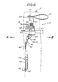
- Figs. 7 and 8 are enlarged side views of the latch device, showing different conditions of the same;
- Figs. 9 to 11 are drawings showing a second embodiment of the present invention, in which:
- Fig. 9 is an exploded view of a latch device of the second embodiment of the present invention;
- Fig. 10 is an enlarged side view of the latch device of the second embodiment;
- Fig. 11 is a back view of an essential part of the latch device of the second embodiment; and
- Fig. 12 is partial exploded view of a latch device of a third embodiment of the present invention.
- Figs. 1 to 8 show a first embodiment of the present invention.
- Referring to Fig. 2, there is shown an automotive rear seat which comprises a seat cushion and a
seatback 10. The seatback 10 is equipped with an inclinable back rest cushion 11. The cushion 11 is usually received in a tunnel "T" formed in theseatback 10. When the cushion 11 is folded as shown in the drawing, the tunnel "T" is exposed to connect a passenger room "B" with a trunk room "A". Although not well shown in the drawing, a known hinge device is arranged between a rear end of the seat cushion and a lower portion of the back rest cushion 11 to achieve a pivotal movement of thecushion 10 relative to theseatback 10. - A
latch device 20A of the first embodiment is mounted to the inclinable back rest cushion 11 to move therewith. As is seen from Fig. 2, thelatch device 20A is substantially entirely installed in the back rest cushion 11. Designated by numeral 11a is a slot which is formed in the back side of the back rest cushion 11 for receiving therein astriker 15 upon raising of the cushion 11. - As is understood from Figs. 3 and 4, and Fig. 1, the
latch device 20A comprises abase member 21 which is secured to a rigid frame member (not shown) installed in a free upper portion 12 (see Fig. 2) of the back rest cushion 11. - As is seen from Fig. 1, the
base member 21 has a raisedcenter portion 21b for housing therein abumper rubber piece 21a. It is to be noted that the parts shown in Fig. 1 are so oriented that the left side of the drawing faces the passenger room "B" and the right side faces the trunk room "A". The raised .center portion 21b is formed with asemicircular cut 21c through which thebumper rubber piece 21a is exposed. Upon raising of the back rest cushion 11, thestriker 15 abuts against therubber piece 21a to bump the movement of the cushion 11. Apivot shaft 22 is fixed to the raisedcenter portion 21b of thebase member 21, which extends upward therefrom. - A
latch member 30 is pivotally disposed about thepivot shaft 22. As will be described in detail hereinafter, thelatch member 30 is latchingly engageable with thestriker 15 which is secured to a wall of the tunnel "T" (see Fig. 2). For this, thelatch member 30 is arranged to be exposed to the slot 11a of the back rest cushion 11. Thelatch member 30 is formed with a raisedflange 31 having abent end 31a. Acoil spring 23 is disposed about thepivot shaft 22 having one end hooked to the raisedflange 31 of thelatch member 30 and the other end hooked to thepivot shaft 22. With thisspring 23, thelatch member 30 is biased to rotate in a clockwise direction in Fig. 3, that is, in a direction to achieve latched engagement with thestriker 15. - An
actuation member 60 is also pivotally disposed about thepivot shaft 22 at a position between thebase member 21 and thelatch member 30. Theactuation member 60 is formed with an upwardly extendingportion 61 and a downwardly extendingportion 62. As is seen from Fig. 1, upon assembly, the upwardly extendingportion 61 is placed behind the raisedflange 31 of thelatch member 30. A top of the upwardly extendingportion 61 is bent to form aflat portion 63 to which apull strap 70 is connected through ascrew 71. Thepull strap 70 is so sized that upon the inclinable back rest cushion 11 assuming its raised latched position, at least a portion of thestrap 70 is exposed to the passenger room "B" to be manipulated by a seat occupant. Usually, due to the biasing force of thespring 23, thebent end 31a of thelatch member 30 abuts on the upwardly extendingportion 61 of theactuation member 60 thereby to bias the same in a clockwise direction in Fig. 3. Thus, when thepull strap 70 is pulled against the biasing force of thespring 23, thelatch member 30 is pivoted in a counterclockwise direction in Fig. 3, that is, in a direction to release the latched engagement between thelatch member 30 and thestriker 15. This latch releasing operation is suppressed by an interfering mechanism which will be described in the following. - The interfering mechanism comprises a
stopper pin 50 which slidably passes through anopening 24 formed in thebase member 21. Theopening 24 is so positioned that when thestopper pin 50 assumes its raised or upper position, it intersects the travelling way of the downwardly extendingportion 62 of theactuation member 60 for the reason which will be clarified as the description proceeds. Thestopper pin 50 has a reducedhead portion 51 and a bentlower portion 52. - For actuation of the
stopper pin 50 from the trunk room "A", an actuation mechanism is incorporated with thestopper pin 50. The actuation mechanism comprises a pivotinglever 42 which is pivotally connected through a pivot pin 42a to aguide bracket 41. Theguide bracket 41 is secured to a rigid member (not shown) of the inclinable back rest cushion 11. Thebracket 41 has an arm which has an opening 41b through which a major portion of thestopper pin 50 slidably passes. The pivotinglever 42 has onearm part 43 which has an opening (no numeral) into which the bentlower portion 52 of thestopper pin 50 is slidably inserted to achieve a pivotal connection therebetween and theother arm part 44 which has an opening (no numeral) to which a bentupper end 45 of anelongate rod 46 is pivotally connected through a known clip (no numeral). A turn over spring 41a is disposed between the pivotinglever 42 and theguide bracket 41 in order to make a turn over action of the pivotinglever 42. That is, when a pivoting movement of thepoviting lever 42 in one direction goes beyond a predetermined angule, the movement is violently accelerated by the spring 41a in a snap action manner. - The
elongate rod 46 extends downward toward abase plate 48 which is secured to another rigid structure of the inclinable back rest cushion 11. Thebase plate 48 has an elongate slot 48a through which a bentlower end 47 of therod 46 is projected into the outside of the back rest cushion 11. Acontrol knob 40 is fixed to the outwardly projected part of the bentlower end 47. Arod holder 49 is fixed to thebase plate 48 to slidably hold therod 46. Usually, due to work of the turn over spring 41a, thecontrol knob 40 assumes either one of the uppermost and lowermost positions defined by the elongate slot 48a of thebase plate 48. As is understood from Fig. 5, when thecontrol knob 40 assumes the uppermost position as illustrated by a phantom line, thestopper pin 50 assumes its lower or inoperative position, while when thecontrol knob 40 assumes the lowermost position as illustrated by a broken line, thestopper pin 50 assumes its upper or operative position, that is, the position to interfere the pivotal movement of the afore-mentionedactuation member 60. - In the following, operation will be described with reference to the drawings, especially Figs. 1, 2 and 5.
- For ease of understanding, the description will be commenced with respect to a condition wherein the inclinable back rest cushion 11 is neatly received in the tunnel "T" with a part of the
pull strap 70 exposed to the passenger room "B" and thestopper pin 50 assumes its inoperative (viz., lower) position. Under this condition, thelatch member 30 is kept engaged with thestriker 15 by the aid of thecoil spring 23 and thecontrol knob 40 assumes its uppermost position. That is, in this condition, the latch device assumes a condition as shown in Fig. 7. - When, for the purpose of inclining the back rest cushion 11, the
pull strap 70 is pulled from the passenger room "B", theactuation member 60 is pivoted in a given direction (viz., in a counterclockwise direction in Fig. 1) pushing at the upwardly extendingportion 61 thereof thebent end 31a of thelatch member 30 in the same direction against the biasing force of thecoil spring 23. With this, thelatch member 30 is disengaged from thestriker 15. Thus, further pulling of thestrap 70 induces a foward inclination of the back rest cushion 11 as shown in Fig. 2. - When, for receiving the cushion 11 into the tunnel "T", the cushion 11 is raised and thrusted into the tunnel "T", the
striker 15 is inserted into the slot 11a of the cushion 11 (see Fig. 2) and brought into contact with acurved head 30a of the latch member 30 (see Fig. 1). Pushing the cushion 11 with a certain force causes thestriker 15 to push thehead 30a of thelatch member 30 away against the biasing force of thespring 23 and thereafter become latched by thelatch member 30 by the work of thespring 23. With this, the cushion 11 assumes the above-mentioned original latched position. - When now the
control knob 40 is pushed down to its lowermost position from the trunk room "A" as is shown in Fig. 8, thestopper pin 50 is projected upward in a snap action manner and assumes its upper or operative position. Under this condition, the upwardly projectedpart 51 of thestopper pin 50 is placed on the travelling way of the downwardly extendingportion 62 of theactuation member 60. Thus, pulling thepull strap 70 from the passenger room "B" can not bring about the pivotal movement of theactuation member 60. Thus, under this condition, the back rest cushion 11 can not be folded even when thepull strap 70 is pulled from the passenger room "B". During this invalid action, a considerable stress is applied to thestopper pin 50 from theactuation member 60. However, the stress is entirely received by thebase member 21 which is tightly secured to the rigid frame member of the back rest cushion 11. Thus, deformation and/or breakage of thestopper pin 50 does not occur. - Figs. 9 to 11 show a second embodiment of the present invention.
- As will be clarified as the description proceeds, in a
latch device 20B of the second embodiment, there are no members which correspond to thestopper pin 50 and the pivotinglever 42 of the first embodiment. - As is well seen from Fig. 9, the
latch device 20B comprises abase member 85 which is secured to a rigid frame member (not shown) installed in a free upper portion 12 (see Fig. 2) of the back rest cushion 11. It is to be noted that the parts shown in Fig. 9 are so oriented that the left side of the drawing faces the passenger room "B" and the right side faces the trunk room "A". Thebase member 85 has a raised center portion (no numeral) for housing therein abumper rubber piece 21a. The raised center portion is formed with a semicircular cut through which thebumper rubber piece 21a is exposed. For the purpose which will be clarified hereinafter, thebase member 85 is formed with a generally U-shapedlower portion 85a, and alignedopenings portion 85a. Aguide plate 90 having an L-shaped cross section is bolted to thebase member 85 in such a manner that an upper flat portion 90a thereof is attached to a lower side of thebase member 85. The upper flat portion 90a is formed with anopening 91 which is mated with theopening 87 of thebase member 85. Although not shown in the drawings, the otherflat portion 90b of theguide plate 90 is tightly bolted to the frame member of the back rest cushion 11. Apivot shaft 22 is fixed to the raised center portion of thebase member 85, which extends upward therefrom. - A
latch member 30 is pivotally disposed about thepivot shaft 22. Thelatch member 30 is formed with a raisedflange 31 having abent end 31a. Acoil spring 23 is disposed about thepivot shaft 22 having one end hooked to the raisedflange 31 of thelatch member 30 and the other end hooked to thepivot shaft 22. Thus, thelatch member 30 is biased to rotate in a clockwise direction in Fig. 9, that is, in a direction to achieve latched engagement with thestriker 15. - An
actuation member 97 is also pivotally disposed about thepivot shaft 22 at a position between thebase member 85 and thelatch member 30. Theactuation member 97 is formed with an upwardly extendingportion 99 and a downwardly extendingportion 98. As is seen from Figs. 10 and 11, the upwardly extendingportion 99 is placed behind the raisedflange 31 of thelatch member 30. A top of the upwardly extendingportion 99 is bent to form a flat portion to which apull strap 70 is connected through ascrew 71. Usually, due to the biasing force of thespring 23, thebent end 31a of thelatch member 30 abuts on the upwardly extendingportion 99 of theactuation member 97 thereby to bias the same in a clockwise direction in Fig. 9. Thus, when thepull strap 70 is pulled against the biasing force of thespring 23, thelatch member 30 is pivoted in a counterclockwise direction in Fig. 9, that is, in a direction to release the latched engagement between thelatch member 30 and thestriker 15. This latch releasing operation is suppressed by an interfering mechanism which will be described in the following. - The interfering mechanism comprises a
stopper rod 80 which slidably passes through theopening 86 of thebase member 86, theopening 91 of theguide plate 90 and theopening 87 of thebase member 85. Theopenings rod 80 assumes its raised or upper position, it intersects the travelling way of the downwardly extendingportion 98 of theactuation member 97. Thestopper rod 80 has a straightupper portion 82 and a bentlower portion 81. - The
stopper rod 80 is axially slidably connected throughclips plate member 95 which is secured to the back rest cushion 11. Theplate member 95 is formed with anelongate slot 95a through which the bentlower portion 81 of therod 80 is projected into the outside of the back rest cushion 11. Acontrol knob 40 is fixed to the outwardly projected part of the bentlower portion 81. A turn over spring 41a is disposed between therod 80 and theplate member 95 in order to make a turn over action of thestopper rod 80. Usually, due to work of the turn over spring 41a, thecontrol knob 40 assumes either one of the uppermost and lowermost positions defined by theelongate slot 95a of theplate member 95. As is understood from Fig. 10, when thecontrol knob 40 assumes the uppermost position as illustrated by a solid line, thestopper rod 80 assumes its upper or operative position, that is, the position to interfere the pivotal movement of theactuation member 97, while, when thecontrol knob 40 assumes the lowermost position as illustrated by a phantom line, thestopper rod 80 assumes its lower or inoperative position. - Fig. 12 shows a part of a third embodiment 20C of the present invention. The latch device 20C of this third embodiment is substantially the same as that of the
second embodiment 20B except for the part which brings about the turn over action of thestopper rod 80. That is, the part comprises anoval guide member 100 of plastics which is formed with a slot 106 the middle portion of which is narrowed. Theguide member 100 is attached to anoval opening 102 formed in theplate member 95. For this attachment, theguide member 100 is formed at its one side with acollar 104 which is snugly received in theoval opening 102 and shaped to match with the aperture 106 of theguide member 100. The bentlower portion 81 of therod 80 is passed through the aperture 106 to be projected into the outside of the back rest cushion 11 and fixed with thecontrol knob 40. It is to be noted that the width of the narrowed portion of the aperture 106 of theguide member 100 is somewhat smaller than the diameter of the bentlower portion 81 of therod 80. Thus, a so-called snap action movement is carried out by therod 80 every time the bentlower portion 81 passes through the narrowed portion of the aperture 106. - Since operation of the
latch devices 20B and 20C of the second and third embodiments will be easily understood from the operation of thefirst embodiment 20A, it will be omitted. Since, in the second and third embodiments, the number of parts used is less than that of the first embodiment, structural simplication of the latch device is much assured as compared with the device of the first embodiment. Furtheremore, because of the reduced number of parts employed therein, possibility of malfunction of the device is reduced. - As will be understood from the foregoing description, the
latch devices
Claims (21)
a latch device for latching said back rest cushion to said backrest when the same is snugly receieved in said tunnel, which comprises:
a striker secured to said seatback;
a latch member pivotally mounted in said back rest cushion in a manner to latchingly engage with said striker upon said cushion being received in said tunnel;
first biasing means for biasing said latch member in a direction to achieve the latched engagement between said latch member and said striker;
an actuation member pivotally mounted in said back rest cushion in a manner to push and pivot said latch member in a releasing direction to release the latched engagement between said latch member and said striker when pivoted in a given direction;
second means having a pin portion which is projectable into a travelling way of said actuation member thereby to interrupt said actuation member from pivoting in said releasing direction;
a base member secured to a rigid portion of said back rest cushion and having an opening through which said pin portion passes; and
third means for manually actuating said second means from a back side of said back rest cushion.
a stopper pin having one end which passes through the opening of said base member;
a pivoting lever pivotally mounted in said back rest cushion, said pivoting lever having one end pivotally connected to said stopper pin; and
an elongate rod having one end pivotally connected to the other end of said pivoting lever, said elongate rod having the other end which is exposed to the outside of said back rest cushion to be manipulated.
an elastic guide member fixed to said elongate opening of said plate member, said guide member having an aperture through which the other end of said elongate rod passes; and
means defining in the aperture of said guide member a narrowed portion the width of which is smaller than the diameter of the other end of said elongate rod.
Applications Claiming Priority (4)
| Application Number | Priority Date | Filing Date | Title |
|---|---|---|---|
| JP852287 | 1987-01-23 | ||
| JP8522/87U | 1987-01-23 | ||
| JP6588787U JPH0431147Y2 (en) | 1987-01-23 | 1987-04-30 | |
| JP65887/87U | 1987-04-30 |
Publications (3)
| Publication Number | Publication Date |
|---|---|
| EP0276761A2 true EP0276761A2 (en) | 1988-08-03 |
| EP0276761A3 EP0276761A3 (en) | 1989-03-01 |
| EP0276761B1 EP0276761B1 (en) | 1992-06-17 |
Family
ID=26343054
Family Applications (1)
| Application Number | Title | Priority Date | Filing Date |
|---|---|---|---|
| EP19880100872 Expired - Lifetime EP0276761B1 (en) | 1987-01-23 | 1988-01-21 | Latch device for inclinable back rest cushion mounted in seatback |
Country Status (4)
| Country | Link |
|---|---|
| US (1) | US4904003A (en) |
| EP (1) | EP0276761B1 (en) |
| JP (1) | JPH0431147Y2 (en) |
| DE (1) | DE3871964T2 (en) |
Cited By (7)
| Publication number | Priority date | Publication date | Assignee | Title |
|---|---|---|---|---|
| DE3841247A1 (en) * | 1988-01-26 | 1989-08-03 | Ikeda Bussan Co | DEVICE FOR LOCKING A REVERSIBLE BACKREST OF A VEHICLE SEAT |
| DE29502987U1 (en) * | 1995-02-22 | 1995-03-30 | ACG Deutschland GmbH, 65428 Rüsselsheim | Unlockable snap lock |
| FR2743589A1 (en) * | 1996-01-11 | 1997-07-18 | Faure Bertrand Equipements Sa | Locking of vehicle rear seat back hatch |
| FR2753419A1 (en) * | 1996-09-19 | 1998-03-20 | Faure Bertrand Equipements Sa | Device for visible locking of vehicle seat foldable back |
| FR2757114A1 (en) * | 1996-12-13 | 1998-06-19 | Ecia Equip Composants Ind Auto | Motor vehicle rear passenger seat locking with visible indication of lock closure |
| ES2124133A1 (en) * | 1994-06-08 | 1999-01-16 | Delphi Automotive Systems Gmbh | Preventing vibration in seat catch operating mechanism |
| CN103939431A (en) * | 2014-05-06 | 2014-07-23 | 广州广电运通金融电子股份有限公司 | Simple latching device |
Families Citing this family (29)
| Publication number | Priority date | Publication date | Assignee | Title |
|---|---|---|---|---|
| DE3907075C1 (en) * | 1989-03-04 | 1990-09-13 | Daimler-Benz Aktiengesellschaft, 7000 Stuttgart, De | |
| US4988134A (en) * | 1990-05-03 | 1991-01-29 | Hoover Universal, Inc. | Inertia latching mechanism with floating striker bar |
| US5476305A (en) * | 1994-12-02 | 1995-12-19 | Atoma International, Inc. | Integrated child seat with safety locking mechanism |
| FR2742389B1 (en) * | 1995-12-19 | 1998-02-20 | Faure Bertrand Equipements Sa | LOCKING DEVICE FOR A MOBILE ELEMENT OF A MOTOR VEHICLE SEAT, WITH LOCKING DISPLAY |
| FR2742390B1 (en) * | 1995-12-19 | 1998-02-20 | Faure Bertrand Equipements Sa | DEVICE FOR LOCKING A CONDOMINABLE MOBILE ELEMENT OF A MOTOR VEHICLE SEAT |
| US5879043A (en) * | 1997-08-26 | 1999-03-09 | Lear Corporation | Vehicle folding rear seat back with side pull interior latch release |
| WO2000013931A1 (en) * | 1998-09-03 | 2000-03-16 | Johnson Controls Technology Company | Vehicle seat with a seat back having a fixed outer structure and an inner pass-through |
| JP4296643B2 (en) * | 1999-07-30 | 2009-07-15 | アイシン精機株式会社 | Seat back lock device |
| US20030085605A1 (en) * | 2001-11-07 | 2003-05-08 | Hentges William J. | Seat and headrest system |
| US20040007909A1 (en) * | 2002-07-09 | 2004-01-15 | Bonk Jeffery T. | Remote-actuated release handle lockout |
| US7959230B2 (en) * | 2003-04-11 | 2011-06-14 | Johnson Controls Technology Company | Seating system for a vehicle |
| FR2856719B1 (en) * | 2003-06-24 | 2007-12-28 | Faurecia Sieges Automobile | LATCHING SYSTEM OF A FIRST ELEMENT WITH A SECOND ELEMENT AND SEAT EQUIPPED WITH SUCH A LATCHING SYSTEM |
| DE102004008828B3 (en) * | 2004-02-20 | 2005-08-04 | Bos Gmbh & Co. Kg | Transporting container device for vehicles has bearing point in region of edge going in first when insertion frame is inserted |
| EP1598270B1 (en) * | 2004-05-21 | 2009-04-29 | Airbus Deutschland GmbH | Aircraft passenger seat with integrated spring element |
| JP4597058B2 (en) * | 2006-01-23 | 2010-12-15 | 三井金属鉱業株式会社 | Vehicle seat lock device |
| DE102006032133A1 (en) * | 2006-07-12 | 2008-01-17 | Dr.Ing.H.C. F. Porsche Ag | Rear seat of a motor vehicle |
| US7997647B2 (en) * | 2007-03-23 | 2011-08-16 | Dan Sjoquist | Safety seat |
| DE102007051180B4 (en) * | 2007-10-25 | 2009-11-12 | Lear Corporation, Southfield | Rear seatback latch |
| DE102008023751A1 (en) * | 2008-05-15 | 2009-11-19 | Grammer Ag | Equipment for a vehicle interior, in particular armrest for vehicle seats |
| CN102171066A (en) * | 2008-10-28 | 2011-08-31 | 李尔公司 | Seat latch |
| IN2012DN03308A (en) * | 2009-10-05 | 2015-10-23 | Johnson Controls Tech Co | |
| US8506014B2 (en) * | 2010-01-21 | 2013-08-13 | Bae Industries, Inc. | Latch mechanism with engagement teeth for connecting a pivotal seatback to a side pillar location of a vehicle interior |
| US8308244B2 (en) * | 2010-09-01 | 2012-11-13 | Honda Motor Co., Ltd. | Apparatus for retaining seatbelt webbing away from a seatback split line |
| US9114740B2 (en) | 2011-01-27 | 2015-08-25 | Bae Industries, Inc. | Trunk located second row seatback dump latch assembly |
| US8777315B2 (en) | 2011-01-27 | 2014-07-15 | Bae Industries, Inc. | High back seat latch with integrated handle |
| US8985692B2 (en) | 2013-03-14 | 2015-03-24 | Bae Industries, Inc. | Fold up or drop down rear seat incorporating a seatback supported rear facing latch for slidably engaging an elongated striker |
| CN203592909U (en) * | 2013-11-18 | 2014-05-14 | 福特环球技术公司 | Fixing assembly of seat back of vehicle and vehicle |
| US9637032B2 (en) * | 2015-04-08 | 2017-05-02 | Ford Global Technologies, Llc | Center armrest lock |
| US10300810B1 (en) * | 2017-12-21 | 2019-05-28 | Ford Global Technologies, Llc | Seat flip up cushion latch |
Citations (8)
| Publication number | Priority date | Publication date | Assignee | Title |
|---|---|---|---|---|
| US2809064A (en) * | 1955-09-21 | 1957-10-08 | Dlugatch Meyer | Hood latch locking device |
| JPS6121837A (en) * | 1984-07-09 | 1986-01-30 | Nissan Motor Co Ltd | Rearseat back for car |
| JPS6121836A (en) * | 1984-07-09 | 1986-01-30 | Nissan Motor Co Ltd | Rearseat back for car |
| JPS6124638A (en) * | 1984-07-13 | 1986-02-03 | Nissan Motor Co Ltd | Device for stopping rear seat back for automobile |
| JPS61220944A (en) * | 1985-03-26 | 1986-10-01 | Nissan Motor Co Ltd | Rear seat back locking apparatus for car |
| JPS61229625A (en) * | 1985-04-03 | 1986-10-13 | Nissan Motor Co Ltd | Rear seat back locking device provided with trunk-through for automobile |
| US4637648A (en) * | 1984-08-07 | 1987-01-20 | Mazda Motor Corporation | Rear seat back locking arrangement for a motor vehicle and the like |
| GB2182620A (en) * | 1985-09-27 | 1987-05-20 | Nissan Motor | Vehicle rear seat providing access to rear space |
Family Cites Families (11)
| Publication number | Priority date | Publication date | Assignee | Title |
|---|---|---|---|---|
| JPS602210B2 (en) * | 1979-12-12 | 1985-01-19 | 日産自動車株式会社 | seat lock device |
| JPS59149833A (en) * | 1983-02-14 | 1984-08-27 | Shiraki Kinzoku Kogyo Kk | Locking device in rear seat for vehicle |
| JPS59190635U (en) * | 1983-06-06 | 1984-12-18 | 富士重工業株式会社 | Trunk-through type rear seat locking device |
| JPS6092633U (en) * | 1983-11-30 | 1985-06-25 | アイシン精機株式会社 | Automobile rear seat back locking device |
| DE3425669A1 (en) * | 1984-07-12 | 1986-01-23 | Adam Opel AG, 6090 Rüsselsheim | LOCKING DEVICE FOR A REAR SEAT BACKREST |
| JPS6157436A (en) * | 1984-08-29 | 1986-03-24 | Nissan Motor Co Ltd | Car rear seat back |
| JPS6147742U (en) * | 1984-09-03 | 1986-03-31 | 日本発条株式会社 | Trunk-through-seat trunk lid locking device |
| DE3433996A1 (en) * | 1984-09-15 | 1986-03-27 | Adam Opel AG, 6090 Rüsselsheim | REAR SEAT BACKREST DESIGNED FOR A MOTOR VEHICLE |
| DE3505047A1 (en) * | 1984-12-15 | 1986-06-26 | Kiekert GmbH & Co KG, 5628 Heiligenhaus | Rear motor vehicle seat with seat bench, back rest which can be simultaneously used as a loading face, and back rest joint fitting |
| JPH0625511B2 (en) * | 1986-07-31 | 1994-04-06 | 三井金属鉱業株式会社 | Lock device |
| DE8626167U1 (en) * | 1986-10-01 | 1986-12-18 | Adam Opel AG, 6090 Rüsselsheim | Locking device for a rear seat backrest |
-
1987
- 1987-04-30 JP JP6588787U patent/JPH0431147Y2/ja not_active Expired
-
1988
- 1988-01-20 US US07/146,066 patent/US4904003A/en not_active Expired - Lifetime
- 1988-01-21 EP EP19880100872 patent/EP0276761B1/en not_active Expired - Lifetime
- 1988-01-21 DE DE8888100872T patent/DE3871964T2/en not_active Expired - Lifetime
Patent Citations (8)
| Publication number | Priority date | Publication date | Assignee | Title |
|---|---|---|---|---|
| US2809064A (en) * | 1955-09-21 | 1957-10-08 | Dlugatch Meyer | Hood latch locking device |
| JPS6121837A (en) * | 1984-07-09 | 1986-01-30 | Nissan Motor Co Ltd | Rearseat back for car |
| JPS6121836A (en) * | 1984-07-09 | 1986-01-30 | Nissan Motor Co Ltd | Rearseat back for car |
| JPS6124638A (en) * | 1984-07-13 | 1986-02-03 | Nissan Motor Co Ltd | Device for stopping rear seat back for automobile |
| US4637648A (en) * | 1984-08-07 | 1987-01-20 | Mazda Motor Corporation | Rear seat back locking arrangement for a motor vehicle and the like |
| JPS61220944A (en) * | 1985-03-26 | 1986-10-01 | Nissan Motor Co Ltd | Rear seat back locking apparatus for car |
| JPS61229625A (en) * | 1985-04-03 | 1986-10-13 | Nissan Motor Co Ltd | Rear seat back locking device provided with trunk-through for automobile |
| GB2182620A (en) * | 1985-09-27 | 1987-05-20 | Nissan Motor | Vehicle rear seat providing access to rear space |
Non-Patent Citations (5)
| Title |
|---|
| PATENT ABSTRACTS OF JAPAN, vol. 10, no. 171 (M-489)[2227], 17th June 1986; & JP-A-61 021 836 (NISSAN JIDOSHA K.K.) 30-01-1986 * |
| PATENT ABSTRACTS OF JAPAN, vol. 10, no. 171 (M-489)[2227], 17th June 1986; & JP-A-61 021 837 (NISSAN JIDOSHA K.K.) 30-01-1986 * |
| PATENT ABSTRACTS OF JAPAN, vol. 10, no. 174 (M-490)[2230], 19th June 1986; & JP-A-61 024 638 (NISSAN JIDOSHA K.K.) 03-02-1986 * |
| PATENT ABSTRACTS OF JAPAN, vol. 11, no. 64 (M-565)[2511], 26th February 1987; & JP-A-61 220 944 (NISSAN MOTOR CO., LTD) 01-10-1986 * |
| PATENT ABSTRACTS OF JAPAN, vol. 11, no. 74 (M-568)[2521], 6th March 1987; & JP-A-61 229 625 (NISSAN MOTOR CO., LTD) 13-10-1986 * |
Cited By (9)
| Publication number | Priority date | Publication date | Assignee | Title |
|---|---|---|---|---|
| DE3841247A1 (en) * | 1988-01-26 | 1989-08-03 | Ikeda Bussan Co | DEVICE FOR LOCKING A REVERSIBLE BACKREST OF A VEHICLE SEAT |
| ES2124133A1 (en) * | 1994-06-08 | 1999-01-16 | Delphi Automotive Systems Gmbh | Preventing vibration in seat catch operating mechanism |
| DE29502987U1 (en) * | 1995-02-22 | 1995-03-30 | ACG Deutschland GmbH, 65428 Rüsselsheim | Unlockable snap lock |
| FR2743589A1 (en) * | 1996-01-11 | 1997-07-18 | Faure Bertrand Equipements Sa | Locking of vehicle rear seat back hatch |
| FR2753419A1 (en) * | 1996-09-19 | 1998-03-20 | Faure Bertrand Equipements Sa | Device for visible locking of vehicle seat foldable back |
| US5855414A (en) * | 1996-09-19 | 1999-01-05 | Bertrand Faure Equipements S.A. | Device for locking a movable element of an automobile vehicle seat onto a fixed element with unlocking indication |
| FR2757114A1 (en) * | 1996-12-13 | 1998-06-19 | Ecia Equip Composants Ind Auto | Motor vehicle rear passenger seat locking with visible indication of lock closure |
| CN103939431A (en) * | 2014-05-06 | 2014-07-23 | 广州广电运通金融电子股份有限公司 | Simple latching device |
| CN103939431B (en) * | 2014-05-06 | 2016-01-20 | 广州广电运通金融电子股份有限公司 | A kind of Simple lock |
Also Published As
| Publication number | Publication date |
|---|---|
| EP0276761A3 (en) | 1989-03-01 |
| JPH0431147Y2 (en) | 1992-07-27 |
| US4904003A (en) | 1990-02-27 |
| DE3871964T2 (en) | 1992-12-03 |
| EP0276761B1 (en) | 1992-06-17 |
| JPS63192142U (en) | 1988-12-12 |
| DE3871964D1 (en) | 1992-07-23 |
Similar Documents
| Publication | Publication Date | Title |
|---|---|---|
| US4904003A (en) | Latch device for inclinable back rest cushion mounted in seatback | |
| US4880264A (en) | Latch device for inclinable back rest cushion mounted in seatback | |
| US5662369A (en) | Device for collapsing a backrest of a backseat of a car | |
| EP0954457B1 (en) | Vehicle seat assembly | |
| US20080001415A1 (en) | Vehicular door handle including secondary latch | |
| US4626028A (en) | Seat for vehicles | |
| US7854461B2 (en) | Slide/flip-up type seat for automobile | |
| US5007680A (en) | Vehicular seat with seatback inclining mechanism | |
| JP4296643B2 (en) | Seat back lock device | |
| WO2008035804A1 (en) | Arrangement lever device for automobile seat | |
| EP0978414A2 (en) | Seat fold mechanism | |
| US5873633A (en) | Retardation lock member for motor vehicle seat component | |
| JPH04213675A (en) | Restraining device for shaking member of vehicle | |
| US4881767A (en) | Latch device for foldable backrest of automotive seat | |
| JPH0986244A (en) | Seat folding device for automobile | |
| US6253634B1 (en) | Vehicular opener device having a recessed operation lever | |
| US3817571A (en) | Automatic seat back latch release | |
| US4940266A (en) | Latch device for foldable backrest of automotive seat | |
| US20040051360A1 (en) | Two way cushion floor latch | |
| US20030075390A1 (en) | Hand brake assembly for a motor vehicle | |
| JP2951878B2 (en) | Car seat folding device | |
| JP2000004971A (en) | Walk-in device for car seat | |
| JP2000110425A (en) | Opener device | |
| US4109935A (en) | Flap buckle | |
| JPS6217311Y2 (en) |
Legal Events
| Date | Code | Title | Description |
|---|---|---|---|
| PUAI | Public reference made under article 153(3) epc to a published international application that has entered the european phase |
Free format text: ORIGINAL CODE: 0009012 |
|
| 17P | Request for examination filed |
Effective date: 19880121 |
|
| AK | Designated contracting states |
Kind code of ref document: A2 Designated state(s): DE FR GB |
|
| PUAL | Search report despatched |
Free format text: ORIGINAL CODE: 0009013 |
|
| AK | Designated contracting states |
Kind code of ref document: A3 Designated state(s): DE FR GB |
|
| 17Q | First examination report despatched |
Effective date: 19910102 |
|
| GRAA | (expected) grant |
Free format text: ORIGINAL CODE: 0009210 |
|
| AK | Designated contracting states |
Kind code of ref document: B1 Designated state(s): DE FR GB |
|
| REF | Corresponds to: |
Ref document number: 3871964 Country of ref document: DE Date of ref document: 19920723 |
|
| RIN2 | Information on inventor provided after grant (corrected) |
Free format text: YAMAZAKI, HIROSHI C/O OHI SEISAKUSHO CO. LTD. * HARA, TOSHIYUKI C/O OHI SEISAKUSHO CO. LTD. * TANAKA, YUJI C/O IKEDA BUSSAN CO., LTD. * MORI, TAKAYUKI |
|
| RIN2 | Information on inventor provided after grant (corrected) |
Free format text: YAMAZAKI, HIROSHI C/O OHI SEISAKUSHO CO. LTD. * HARA, TOSHIYUKI C/O OHI SEISAKUSHO CO. LTD. * TANAKA, YUJI,C/O IKEDA BUSSAN CO., LTD. * MORI, TAKAYUKI, C/O IKEDA BUSSAN CO., LTD. |
|
| ET | Fr: translation filed | ||
| PLBE | No opposition filed within time limit |
Free format text: ORIGINAL CODE: 0009261 |
|
| STAA | Information on the status of an ep patent application or granted ep patent |
Free format text: STATUS: NO OPPOSITION FILED WITHIN TIME LIMIT |
|
| 26N | No opposition filed | ||
| PGFP | Annual fee paid to national office [announced via postgrant information from national office to epo] |
Ref country code: FR Payment date: 19990111 Year of fee payment: 12 |
|
| PGFP | Annual fee paid to national office [announced via postgrant information from national office to epo] |
Ref country code: GB Payment date: 19990121 Year of fee payment: 12 |
|
| PGFP | Annual fee paid to national office [announced via postgrant information from national office to epo] |
Ref country code: DE Payment date: 19990201 Year of fee payment: 12 |
|
| PG25 | Lapsed in a contracting state [announced via postgrant information from national office to epo] |
Ref country code: GB Free format text: LAPSE BECAUSE OF NON-PAYMENT OF DUE FEES Effective date: 20000121 |
|
| GBPC | Gb: european patent ceased through non-payment of renewal fee |
Effective date: 20000121 |
|
| PG25 | Lapsed in a contracting state [announced via postgrant information from national office to epo] |
Ref country code: FR Free format text: LAPSE BECAUSE OF NON-PAYMENT OF DUE FEES Effective date: 20000929 |
|
| PG25 | Lapsed in a contracting state [announced via postgrant information from national office to epo] |
Ref country code: DE Free format text: LAPSE BECAUSE OF NON-PAYMENT OF DUE FEES Effective date: 20001101 |
|
| REG | Reference to a national code |
Ref country code: FR Ref legal event code: ST |