EP0276484A1 - Solarspiegelanordnung - Google Patents
Solarspiegelanordnung Download PDFInfo
- Publication number
- EP0276484A1 EP0276484A1 EP87119338A EP87119338A EP0276484A1 EP 0276484 A1 EP0276484 A1 EP 0276484A1 EP 87119338 A EP87119338 A EP 87119338A EP 87119338 A EP87119338 A EP 87119338A EP 0276484 A1 EP0276484 A1 EP 0276484A1
- Authority
- EP
- European Patent Office
- Prior art keywords
- parabolic
- mirror
- clamping profile
- solar
- axis
- Prior art date
- Legal status (The legal status is an assumption and is not a legal conclusion. Google has not performed a legal analysis and makes no representation as to the accuracy of the status listed.)
- Withdrawn
Links
- 230000006835 compression Effects 0.000 claims abstract description 14
- 238000007906 compression Methods 0.000 claims abstract description 14
- 230000005855 radiation Effects 0.000 claims abstract description 12
- 239000000969 carrier Substances 0.000 claims description 26
- 229910000831 Steel Inorganic materials 0.000 claims description 2
- 239000010959 steel Substances 0.000 claims description 2
- 238000005452 bending Methods 0.000 description 2
- 238000003780 insertion Methods 0.000 description 2
- 230000037431 insertion Effects 0.000 description 2
- 238000004519 manufacturing process Methods 0.000 description 2
- 230000003287 optical effect Effects 0.000 description 2
- 230000001154 acute effect Effects 0.000 description 1
- 230000005540 biological transmission Effects 0.000 description 1
- 230000006735 deficit Effects 0.000 description 1
- 238000006073 displacement reaction Methods 0.000 description 1
- 230000001771 impaired effect Effects 0.000 description 1
Images



Classifications
-
- F—MECHANICAL ENGINEERING; LIGHTING; HEATING; WEAPONS; BLASTING
- F24—HEATING; RANGES; VENTILATING
- F24S—SOLAR HEAT COLLECTORS; SOLAR HEAT SYSTEMS
- F24S30/00—Arrangements for moving or orienting solar heat collector modules
- F24S30/40—Arrangements for moving or orienting solar heat collector modules for rotary movement
- F24S30/42—Arrangements for moving or orienting solar heat collector modules for rotary movement with only one rotation axis
- F24S30/425—Horizontal axis
-
- F—MECHANICAL ENGINEERING; LIGHTING; HEATING; WEAPONS; BLASTING
- F24—HEATING; RANGES; VENTILATING
- F24S—SOLAR HEAT COLLECTORS; SOLAR HEAT SYSTEMS
- F24S23/00—Arrangements for concentrating solar-rays for solar heat collectors
- F24S23/70—Arrangements for concentrating solar-rays for solar heat collectors with reflectors
- F24S23/74—Arrangements for concentrating solar-rays for solar heat collectors with reflectors with trough-shaped or cylindro-parabolic reflective surfaces
- F24S23/745—Arrangements for concentrating solar-rays for solar heat collectors with reflectors with trough-shaped or cylindro-parabolic reflective surfaces flexible
-
- F—MECHANICAL ENGINEERING; LIGHTING; HEATING; WEAPONS; BLASTING
- F24—HEATING; RANGES; VENTILATING
- F24S—SOLAR HEAT COLLECTORS; SOLAR HEAT SYSTEMS
- F24S30/00—Arrangements for moving or orienting solar heat collector modules
- F24S2030/10—Special components
- F24S2030/13—Transmissions
- F24S2030/134—Transmissions in the form of gearings or rack-and-pinion transmissions
-
- F—MECHANICAL ENGINEERING; LIGHTING; HEATING; WEAPONS; BLASTING
- F24—HEATING; RANGES; VENTILATING
- F24S—SOLAR HEAT COLLECTORS; SOLAR HEAT SYSTEMS
- F24S30/00—Arrangements for moving or orienting solar heat collector modules
- F24S2030/10—Special components
- F24S2030/14—Movement guiding means
-
- Y—GENERAL TAGGING OF NEW TECHNOLOGICAL DEVELOPMENTS; GENERAL TAGGING OF CROSS-SECTIONAL TECHNOLOGIES SPANNING OVER SEVERAL SECTIONS OF THE IPC; TECHNICAL SUBJECTS COVERED BY FORMER USPC CROSS-REFERENCE ART COLLECTIONS [XRACs] AND DIGESTS
- Y02—TECHNOLOGIES OR APPLICATIONS FOR MITIGATION OR ADAPTATION AGAINST CLIMATE CHANGE
- Y02E—REDUCTION OF GREENHOUSE GAS [GHG] EMISSIONS, RELATED TO ENERGY GENERATION, TRANSMISSION OR DISTRIBUTION
- Y02E10/00—Energy generation through renewable energy sources
- Y02E10/40—Solar thermal energy, e.g. solar towers
- Y02E10/47—Mountings or tracking
Definitions
- the invention relates to a solar mirror arrangement with an elongated support frame, on which resiliently flexible mirror plates, in particular mirror sheets, are attached in a parabolic curve and in the focal line of the mirror plates an elongated solar radiation receiver and which can be pivoted about an axis running parallel to the cylinder axis.
- Such solar mirror arrangements are used in particular in sun-rich countries for solar energy generation.
- large-area mirror arrangements are required.
- their production is associated with considerable effort.
- the aim of the invention is therefore to provide a solar mirror arrangement of the type mentioned at the outset, with which large-area sunlight receiving surfaces can be realized in the best possible optical quality and low weight without the expenditure for the production of the solar mirror arrangement becoming excessively high.
- inexpensive components that are on the market should be used as far as possible without in particular the optical quality of the mirror arrangement, i.e. the exactness of the concentration of sunlight on the radiation receiver is impaired.
- the solar mirror arrangement should be stable and reliable even over long operating times and even with significant temperature differences between day and night.
- the invention provides that the support frame has two spaced-apart and parallel clamping profile carriers, the ends of the cylinder webs extending between them on their mutually facing sides, on the concave parabolic edge of which the mirror plates are positively arranged to parallel to their pivot axis extending pivotally and pivotably on the side of the pivot axis facing the parabolic edge in an offset from this has an elongated compression stop extending parallel to the pivot axis, against which the end edges of the mirror plate rest, whereby the mirror plate is held taut against the parabola edge, and that can be removed from the end edge by loosening and pivoting the or the clamping profile carrier about the pivot axis.
- the parabolic surface is realized according to the invention by the parabolic edges of the very narrow parabolic webs, which are arranged next to one another on the supporting frame at suitable intervals and the mirror plates are pressed against their parabola edge in the sense of compression in such a way that the mirror plates abut the parabola edges of the parabolic webs in a form-fitting manner.
- this form-fitting concern in a simple manner, i.e.
- the clamping profile carriers are used, which allow easy insertion of the mirror plates, which are initially only roughly parabolic, whereby the compression of the mirror plates and the form-fitting contact with the mirror plates during the subsequent pivoting Parabolic edges of the parabolic webs take place, which in turn have previously been pivotally connected to the clamping profile supports.
- the non-pre-bent mirror plates are inserted, they are bent into a preliminary parabolic shape due to their own weight.
- the clamping profile carrier has essentially a hollow cylindrical basic shape and has a groove-like cutout on the side supporting the mirror plate, the corner edge of which forms the compression stop.
- the clamping profile carrier ins special provision should be made for the clamping profile carrier to have a longitudinal slot on the side supporting the mirror surface, in which a slide bearing bearing defining the pivot axis is held in a longitudinally displaceable manner.
- the longitudinal slot is preferably located in the middle of the groove-like cutout at the bottom thereof.
- the slides can be locked in any position along the clamping profile carrier. In this way, the slides can be moved to those points after the mounting of the clamping profile carrier and can be determined where the parabolic bars are to be arranged to support the mirror plates.
- a practical embodiment is characterized in that a pivot pin connected to the ends of a parabolic bar engages in the pivot bearing. It is particularly expedient here if the pivot bearing and the pivot pin can be clamped against one another essentially in the direction of the tangent of the parabolic surface at that point in the direction in which the end edge of the mirror plate can be pressed more or less against the compression stop. In this way it is still possible to fine-tune the arrangement of the ends of the parabolic webs relative to the clamping profile carriers, this relative tensioning being most conveniently carried out by an adjusting screw screwed into the pivot bearing.
- each individual parabolic bar is still a relatively unstable structure, especially against bending in the plane, a further development of the invention provides that two spaced adjacent parabolic bars are connected to a structural unit by connecting bars.
- box-like profile structures are created which have a very high internal stability, which is then increased by the attachment to the clamping profile carriers.
- the parabolic bars and the mirror plates are stabilized by the mutual bracing via the clamping profile supports.
- a particularly expedient structural embodiment is characterized in that the two clamping profile carriers are supplemented at their two ends by connecting carriers to form a frame, the connection between the clamping profile carrier and the connecting carriers being detachable and designed in such a way that the clamping profile carriers about the pivot axis are optionally in the release - or clamping position are pivotable.
- a further advantageous embodiment is characterized in that the ends of the clamping profile carriers are optionally attached diametrically to rigid circular rings via the connecting carriers, the axes of which run parallel to the parabolic axis and the diameter of which essentially corresponds to the distance between the two clamping profile carriers.
- the circular rings are mounted on rollers and can be rotated in a controlled manner about their common axis.
- the rigid circular rings are thus used at the same time for holding the solar mirror arrangement and for its controlled rotation.
- the controlled rotation ensures that the solar radiation falls on the solar mirror arrangement from the front in the optimal direction at all times, so that the solar energy is largely concentrated on the radiation receiver located in the focal line.
- the latter is expediently attached to the circular rings opposite the mirror plates.
- the parabolic edge of the parabolic webs is parabolic.
- the sunlight can be realized particularly precisely concentrating parabolic mirrors on the radiation receiver.
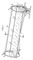
- base frames 29 are provided on the front ends of a solar mirror arrangement according to the invention, of which only that provided on the right front side is shown in FIG. 1. These base frames 29 are arranged on the ground. Plastic rollers 30 with a horizontal axis of rotation are rotatably mounted on the base frames 29 at a circumferential distance, on which a circular ring 26 made of steel is rotatably but axially guided about its horizontally running central axis 31.
- the rotary drive of one of the circular rings 26 can in a manner not shown by means of a Ge Drive strongly reduced electric motor take place, or acts on the circumference of the ring 26 via a transmission.
- connection carriers 25 which extend diametrically through the circular rings 26 and, with their ends projecting somewhat beyond the circular rings 26, bear elongated clamping profile carriers 11, which extend from the connection carrier 25 of the one circular ring 26 to the connection carrier 25 extend at a considerable axial distance from it arranged parallel circular ring 26.
- clamping profile carriers 11 Between the two parallel clamping profile carriers 11, thin and elastically flexible mirror plates 15 are arranged in the manner described in more detail below in a parabolically curved shape.
- the two circular rings 26 shown in FIG. 1 there are a total of seven mirror plates 15 in direct contact next to one another or on the connecting supports 25, which have a rectangular shape in the non-curved state, the longer side of the rectangle running in the later circumferential direction.
- Stiffening struts 32 extend from the lower regions of the circular rings 26 to the central regions of the two clamping profile carriers 11 in order to create an overall arrangement which is as rigid as possible in terms of bending and connection.
- parabolic webs 12 are arranged behind the mirror sheets 15, each of which has a parabolic edge 17 facing the mirror sheets 15.
- the parabolic webs 12 and their parabolic edges 17 extend in the circumferential direction of the mirror plates 15.
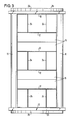
- FIG. 3 in contrast to FIG. 1, for the sake of simplicity only three mirror plates 15 arranged side by side are shown.
- the same reference numbers denote corresponding components in all exemplary embodiments.
- two parabolic webs 12 which are arranged next to one another at a distance, are connected to one another by a connecting web 24 running in the longitudinal direction of the arrangement to form a larger structural unit. 3, three such units are provided next to each other at a distance.
- the flat surfaces of the parabolic webs 12 and the connecting webs 24 are perpendicular to the parabolic-cylindrical curved mirror surfaces 15.
- a pivot pin 23 extending parallel to the parabolic axis is arranged at the very end, which protrudes on both sides over each parabolic web 12 according to FIG 21 engages, which are provided on slides 22, which are arranged in the clamping profile carriers 11 so as to be displaceable in the longitudinal direction.
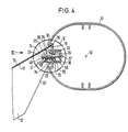
- 4 has a groove-like cutout 19, in the base of which a longitudinal slot 20 is provided. The edge webs 33 of this longitudinal slot 20 are encompassed by guide grooves 34 of the slide 22 in a sliding fit, such that the slide 22 is securely held on all sides on the clamping profile carrier 11, but can be displaced in the longitudinal direction.
- This slide 21 has a threaded bore 35 into which a clamping screw 36 is screwed, the end of which can be pressed against the bottom 37 of a clamping web 38 provided on the clamping profile carrier 11.
- the screw has a screwdriver slot 39 in its head, by means of which the screw can be actuated by a screwdriver and clamped against the bottom 37 of the clamping web 38 when the slide 22 is at a certain point along the length expansion of the clamping profile carrier 11 is to be determined.
- each slide 22 which extends to somewhat over the outer circumference of the clamping profile carrier 11 in the direction of the mirror plates 15 and there engages around the pivot pin 23 which is inserted through the parabolic webs 12.
- threaded bore 40 On the inside of each pivot bearing there is an approximately tangential to the parabolic surface at this point threaded bore 40 through which an adjusting bolt 41 is screwed, which is supported with its end on the outer circumference of the pivot pin 23.
- the best option would be a tapped hole that is normal to the imaginary connecting line of the two opposite bores of a parabolic bridge in order not to subsequently cause any tension (forces) on the parabolic bridge.
- the tapped hole is to be made due to the geometric shape of the clamping profile.
- the arrangement of the parabolic webs 17 by means of the pivot pin 23 on the pivot bearing 21 of the slide 22 is such that the tangent of the parabolic edge 17 in the end region of each parabolic web 12 essentially opens into the upper corner edge of the groove-like cutout 19. In this way, it is possible that the end edges 18 of the mirror plates 15, which are placed on the parabolic edges 17 of the parabolic webs 12 in a curved manner, lie in this corner edge, which thus forms a compression stop 16 for the end edges 18.
- each parabolic bar 12 is surrounded by two slides 21 which are mirror-symmetrical to one another and which clamp the parabolic bar 12 between them and at the same time fix its position perpendicular to the mirror surfaces 15.
- the clamping profile supports 11 are mounted with their ends on the connecting supports 25 so as to be pivotable about the pivot axis 14 of the pivot pin 23.
- the clamping profile carrier 11 can only be shown schematically at the ends indicated mounting pins 42 may be provided which engage in elongated holes 43, shown in dashed lines, in the connecting supports 25 around the pivot axis 14 and can be fixed in a certain pivoting position relative to the connecting supports 25 by bolts, not shown.
- the clamping profile carriers 11 can be pivoted about the pivot axis 14.
- an elongated radiation receiver 28 is arranged opposite the connecting supports 25 and the mirror plates 15, which is fastened via fastening webs 27 to the two stiff circular rings 26 arranged at a distance.
- the sunlight 44 which strikes the mirror plates 25 in parallel and from the front is concentrated in the focal line of the mirror plates 25, where the radiation receiver 28 is arranged.
- each clamping profile carrier 11 extends parallel to its longitudinal axis 13.
- the assembly of the solar mirror arrangement according to the invention proceeds as follows:
- the mirror plates 15 are placed on the parabolic edges 17 of the parabolic segments 12, taking approximately the dashed position shown in FIG. 5, in which the end edges 15 still have a certain small distance from the upsetting stops 16, so that the insertion can be carried out without problems.
- the clamping profile carriers 11 are pivoted in the direction of the dashed arrow in FIG. 5, with the compression stops 16 in contact with the end edges 18 of the mirror plates 15 come so that when pivoting further into the tensioned position shown in FIG. 5, the mirror plates 15 are pressed firmly and positively onto the parabolic edge 17 of the cylinder webs 12.
- the clamping position of the clamping profile supports 11 are fixed in the clamping position by tightening the nuts at the connection point to the connecting supports 25, so that there is now an exactly aligned and optically perfect parabolic mirror arrangement .
- the disassembly is done in reverse.
- the assembly of the parabolic bars 12 is correspondingly simple.
- the parabolic webs 12 assembled into larger structural units according to FIG. 3 are hooked into the pivot bearings 21, which are preferably open at the top, by means of the pivot pins 23, the overall arrangements being brought into the correct position by lateral displacement of the slides 21 can.
- the slides 21 are then pressed onto the associated parabolic webs 12 from both sides and fixed in this position by the screws 36.
- the fine adjustment can then be carried out by turning the adjusting screws 41.
- FIG. 7 several solar mirror arrangements according to FIG. 1 can be arranged one behind the other and rotatably coupled to one another in a suitable manner. In this way, a single motor 45 is sufficient to drive all coupled solar mirror arrangements.
- the webs 12 could also deviate somewhat from the parabolic shape and e.g. be approximately circular if only the predominant part of the solar radiation falls on the radiation receiver 28.
Landscapes
- Engineering & Computer Science (AREA)
- Physics & Mathematics (AREA)
- Life Sciences & Earth Sciences (AREA)
- Sustainable Development (AREA)
- Sustainable Energy (AREA)
- Thermal Sciences (AREA)
- Chemical & Material Sciences (AREA)
- Combustion & Propulsion (AREA)
- Mechanical Engineering (AREA)
- General Engineering & Computer Science (AREA)
- Optical Elements Other Than Lenses (AREA)
- Aerials With Secondary Devices (AREA)
Applications Claiming Priority (2)
| Application Number | Priority Date | Filing Date | Title |
|---|---|---|---|
| DE3644759 | 1986-12-30 | ||
| DE19863644759 DE3644759A1 (de) | 1986-12-30 | 1986-12-30 | Solarspiegelanordnung |
Publications (1)
| Publication Number | Publication Date |
|---|---|
| EP0276484A1 true EP0276484A1 (de) | 1988-08-03 |
Family
ID=6317401
Family Applications (1)
| Application Number | Title | Priority Date | Filing Date |
|---|---|---|---|
| EP87119338A Withdrawn EP0276484A1 (de) | 1986-12-30 | 1987-12-29 | Solarspiegelanordnung |
Country Status (4)
| Country | Link |
|---|---|
| US (1) | US4820033A (https=) |
| EP (1) | EP0276484A1 (https=) |
| DE (1) | DE3644759A1 (https=) |
| IL (1) | IL84909A0 (https=) |
Cited By (2)
| Publication number | Priority date | Publication date | Assignee | Title |
|---|---|---|---|---|
| WO2007051928A3 (fr) * | 2005-11-07 | 2007-07-05 | Frederic Conchy | Module solaire elementaire destine a un dispositif de recuperation du rayonnement solaire |
| EP2250526A4 (en) * | 2008-01-14 | 2013-08-21 | Focal Point Energy Inc | SOLAR SENSITIVE MEMBRANE SENSOR WITH SUPPORTING EDGE |
Families Citing this family (33)
| Publication number | Priority date | Publication date | Assignee | Title |
|---|---|---|---|---|
| US5325844A (en) * | 1992-02-11 | 1994-07-05 | Power Kinetics, Inc. | Lightweight, distributed force, two-axis tracking, solar radiation collector structures |
| US6994082B2 (en) * | 2002-09-20 | 2006-02-07 | Hochberg Eric B | Lightweight, low-cost solar energy collector |
| US20060150967A1 (en) * | 2003-01-24 | 2006-07-13 | Erwin Hoelle | Solar collector |
| AU2004254282B2 (en) * | 2003-07-01 | 2009-10-01 | Areva Solar Pty Ltd | Carrier and drive arrangement for a solar energy reflector system |
| AU2003903335A0 (en) * | 2003-07-01 | 2003-07-17 | Solar Heat And Power Pty. Ltd. | Carrier and Drive Arrangement for a Solar Energy reflector System |
| AU2003903341A0 (en) * | 2003-07-01 | 2003-07-17 | Solar Heat And Power Pty. Ltd. | Carrier for solar energy reflector element |
| WO2007087680A1 (en) * | 2006-02-03 | 2007-08-09 | Miralite Pty Ltd | Improved trough reflectors for solar energy collectors |
| AU2006341135B2 (en) * | 2006-03-28 | 2011-09-01 | Rahmi Oguz Capan | Parabolic solar trough systems with rotary tracking means |
| WO2007129146A1 (en) * | 2006-05-05 | 2007-11-15 | Capan Rahmi Oguz | Hyperbolic solar trough field system |
| US7950387B2 (en) * | 2006-06-08 | 2011-05-31 | Sopogy, Inc. | Use of identical components in solar energy collectors |
| EP2061716A2 (en) * | 2006-07-28 | 2009-05-27 | Megawatt Solar LLC | Reflector assemblies, systems, and methods for collecting solar radiation for photovoltaic electricity generation |
| WO2008147560A1 (en) * | 2007-05-24 | 2008-12-04 | Megawatt Solar, Inc. | Photovoltaic collection systems, friction drives, and method for tracking the sun and avoiding wind damage |
| AU2008262309A1 (en) | 2007-06-06 | 2008-12-18 | Areva Solar, Inc. | Combined cycle power plant |
| US20090126364A1 (en) * | 2007-06-06 | 2009-05-21 | Ausra, Inc. | Convective/radiative cooling of condenser coolant |
| US8378280B2 (en) * | 2007-06-06 | 2013-02-19 | Areva Solar, Inc. | Integrated solar energy receiver-storage unit |
| EP2174072A1 (en) * | 2007-06-08 | 2010-04-14 | Sopogy, Inc. | Parking solar energy collectors |
| US8641861B2 (en) * | 2007-06-15 | 2014-02-04 | The Boeing Company | Solar collector devices and methods of assembly |
| PE20090843A1 (es) * | 2007-07-10 | 2009-07-24 | Trevijano Jose Javier Alejo | Concentrador de energia solar y proceso de montaje |
| ES2352990B1 (es) * | 2007-07-10 | 2012-01-25 | Jose Javier Alejo Trevijano | Concentrador de energía solar y proceso de montaje. |
| AU2008274136A1 (en) * | 2007-07-10 | 2009-01-15 | Jose Javier Alejo Trevijano | Solar energy concentrator and assembly method |
| US20090056703A1 (en) | 2007-08-27 | 2009-03-05 | Ausra, Inc. | Linear fresnel solar arrays and components therefor |
| US9022020B2 (en) | 2007-08-27 | 2015-05-05 | Areva Solar, Inc. | Linear Fresnel solar arrays and drives therefor |
| WO2009048879A2 (en) * | 2007-10-12 | 2009-04-16 | Megawatt Solar, Inc. | Methods, systems, and computer readable media for controlling orientation of a photovoltaic collection system to track apparent movement of the sun |
| US7887188B2 (en) * | 2008-01-18 | 2011-02-15 | Laird Knight | Spherical heliostat |
| US8274030B2 (en) | 2008-09-16 | 2012-09-25 | D-Rev Design for the Other Ninety Percent | Solar concentrator and portable tracking device |
| US8490620B1 (en) * | 2008-10-23 | 2013-07-23 | Lockheed Martin Corporation | In-ground solar trough |
| ES2378730B1 (es) * | 2009-03-04 | 2013-03-19 | Mecanizados Solares, S.L. | Perfeccionamientos en la sustentación de un seguidor solar. |
| US9268069B2 (en) * | 2010-01-29 | 2016-02-23 | Thomas Boeman | Parabolic reflector |
| CA2843780C (en) | 2011-08-04 | 2015-02-03 | 6637418 Canada Inc. Carrying On Business As Rackam | Heat exchanger and method of manufacturing thereof |
| US10145365B2 (en) | 2013-03-20 | 2018-12-04 | Brenmiller Energy Ltd. | Integrated thermal storage, heat exchange, and steam generation |
| IL225456A (en) * | 2013-03-24 | 2017-01-31 | Brenmiller Energy Ltd | Modular solar field |
| IT202300007152A1 (it) * | 2023-04-13 | 2024-10-13 | Mauro Dandrea | Dispositivo concentratore solare e impianto dotato di tale dispositivo |
| DE102024131838A1 (de) * | 2024-10-31 | 2026-04-30 | Deutsches Zentrum für Luft- und Raumfahrt e.V. | Parabolrinnenkollektormodul sowie Parabolrinnenkollektoreinheit |
Citations (6)
| Publication number | Priority date | Publication date | Assignee | Title |
|---|---|---|---|---|
| US4106484A (en) * | 1977-03-31 | 1978-08-15 | Mega Analytical Research Services, Inc. | Adjustable solar concentrator |
| US4106480A (en) * | 1975-12-15 | 1978-08-15 | Halm Instrument Co., Inc. | Reflective solar heat collector |
| US4136671A (en) * | 1977-03-24 | 1979-01-30 | Whiteford Carl L | Electromagnetic radiation reflector |
| EP0015487A1 (de) * | 1979-02-27 | 1980-09-17 | Nihon Chemical Plant Consultant Co., Ltd. | Einrichtung zur Nutzbarmachung von Solarwärme |
| US4359041A (en) * | 1979-10-31 | 1982-11-16 | Snodgrass Erlin E | Light energy concentrating device |
| US4390241A (en) * | 1975-07-11 | 1983-06-28 | Vulcan Australia Limited | Reflective trough structure |
Family Cites Families (8)
| Publication number | Priority date | Publication date | Assignee | Title |
|---|---|---|---|---|
| US4103672A (en) * | 1976-05-21 | 1978-08-01 | Meyer Warren A | Solar collector |
| US4071017A (en) * | 1976-07-01 | 1978-01-31 | General Atomic Company | Tensioned reflector support system |
| US4135493A (en) * | 1977-01-17 | 1979-01-23 | Acurex Corporation | Parabolic trough solar energy collector assembly |
| US4127926A (en) * | 1977-06-16 | 1978-12-05 | Whiteline, Inc. | Method of making solar reflectors |
| US4139270A (en) * | 1977-09-06 | 1979-02-13 | Dotson James T | Panel mounting apparatus |
| US4268332A (en) * | 1978-05-08 | 1981-05-19 | Sun Trac Industries, Inc. | Method of making precision parabolic reflector apparatus |
| US4293192A (en) * | 1980-05-27 | 1981-10-06 | Bronstein Allen I | Solar reflector with flexible sheet tightly secured around form surfaces |
| FR2516220B1 (fr) * | 1981-11-12 | 1986-01-17 | Rossignol Sa | Collecteur cylindro-parabolique d'energie solaire |
-
1986
- 1986-12-30 DE DE19863644759 patent/DE3644759A1/de active Granted
-
1987
- 1987-12-22 IL IL84909A patent/IL84909A0/xx unknown
- 1987-12-23 US US07/137,209 patent/US4820033A/en not_active Expired - Fee Related
- 1987-12-29 EP EP87119338A patent/EP0276484A1/de not_active Withdrawn
Patent Citations (6)
| Publication number | Priority date | Publication date | Assignee | Title |
|---|---|---|---|---|
| US4390241A (en) * | 1975-07-11 | 1983-06-28 | Vulcan Australia Limited | Reflective trough structure |
| US4106480A (en) * | 1975-12-15 | 1978-08-15 | Halm Instrument Co., Inc. | Reflective solar heat collector |
| US4136671A (en) * | 1977-03-24 | 1979-01-30 | Whiteford Carl L | Electromagnetic radiation reflector |
| US4106484A (en) * | 1977-03-31 | 1978-08-15 | Mega Analytical Research Services, Inc. | Adjustable solar concentrator |
| EP0015487A1 (de) * | 1979-02-27 | 1980-09-17 | Nihon Chemical Plant Consultant Co., Ltd. | Einrichtung zur Nutzbarmachung von Solarwärme |
| US4359041A (en) * | 1979-10-31 | 1982-11-16 | Snodgrass Erlin E | Light energy concentrating device |
Cited By (3)
| Publication number | Priority date | Publication date | Assignee | Title |
|---|---|---|---|---|
| WO2007051928A3 (fr) * | 2005-11-07 | 2007-07-05 | Frederic Conchy | Module solaire elementaire destine a un dispositif de recuperation du rayonnement solaire |
| US8704080B2 (en) | 2005-11-07 | 2014-04-22 | Exosun | Basic solar module for a device collecting solar radiation |
| EP2250526A4 (en) * | 2008-01-14 | 2013-08-21 | Focal Point Energy Inc | SOLAR SENSITIVE MEMBRANE SENSOR WITH SUPPORTING EDGE |
Also Published As
| Publication number | Publication date |
|---|---|
| IL84909A0 (en) | 1988-06-30 |
| DE3644759A1 (de) | 1988-07-14 |
| US4820033A (en) | 1989-04-11 |
| DE3644759C2 (https=) | 1989-11-09 |
Similar Documents
| Publication | Publication Date | Title |
|---|---|---|
| EP0276484A1 (de) | Solarspiegelanordnung | |
| EP0654377A2 (de) | Rückblickspiegel für Kraftfahrzeuge | |
| DE2233639A1 (de) | Halterung fuer optische bauelemente, insbesondere in einem lasersystem | |
| DE3923932A1 (de) | Bausatz fuer einen fahrzeugaussenspiegel | |
| DE2800868C2 (de) | Befestigungsanordnung für Förderband-Reinigungsvorrichtungen | |
| DE4306802C1 (de) | Deckenstativ | |
| DE3127872C2 (de) | Wendestangenwagen | |
| DE3112214A1 (de) | "dachtraeger fuer kraftfahrzeuge" | |
| EP0713801A2 (de) | Scheinwerfer für Fahrzeuge | |
| EP4005834B1 (de) | Fahrwerksaufhängung mit exzentrischem justierelement | |
| EP0425935A2 (de) | Vorrichtung zum parallelen Spannen von Druckplatten | |
| DE4444162C2 (de) | Umfassungszarge | |
| DE69109555T2 (de) | Scharnier für eine Fahrzeugtür. | |
| DE3425388C2 (de) | Schlauchboot | |
| EP0547438A1 (de) | Einachsscharnier | |
| EP0890435A1 (de) | Vorrichtung zum Befestigen einer biegsamen Platte auf dem Umfang des Zylinders einer Lackiermaschine | |
| EP1352146A1 (de) | Lamelle für beschattungs- und/oder lichtleiteinrichtungen für gebäude | |
| DE2458942C3 (de) | Vorrichtung zur verstellbaren Befestigung eines feststehenden Scheinwerfers auf einer Tragplatte | |
| EP4515111B1 (de) | Haltevorrichtung und halterungsset für werbeträgersysteme | |
| DE2738859A1 (de) | Traeger fuer parabolsonnenkollektoren | |
| DE2207138C3 (de) | Vorrichtung zum Aufspannen einer biegsamen Druckplatte auf eine Sattelplatte | |
| DE2031711A1 (de) | Druckplatten Festspannvornchtung | |
| EP0585741A2 (de) | Halteeinrichtung zum Befestigen und Spannen grossflächiger Bauteile | |
| DE2315982A1 (de) | Befestigungsvorrichtung fuer motoren, getriebegehaeuse, variatoren oder dgl., insbesondere fuer einen elektromotor, der bei einem maschinenwerkzeug oder dgl. eine riemenscheibe treibt | |
| EP0291899A1 (de) | Spannvorrichtung |
Legal Events
| Date | Code | Title | Description |
|---|---|---|---|
| PUAI | Public reference made under article 153(3) epc to a published international application that has entered the european phase |
Free format text: ORIGINAL CODE: 0009012 |
|
| 17P | Request for examination filed |
Effective date: 19880229 |
|
| AK | Designated contracting states |
Kind code of ref document: A1 Designated state(s): AT BE CH DE ES FR GB GR IT LI LU NL SE |
|
| RBV | Designated contracting states (corrected) |
Designated state(s): DE ES FR GR IT |
|
| 17Q | First examination report despatched |
Effective date: 19900205 |
|
| STAA | Information on the status of an ep patent application or granted ep patent |
Free format text: STATUS: THE APPLICATION IS DEEMED TO BE WITHDRAWN |
|
| 18D | Application deemed to be withdrawn |
Effective date: 19910730 |
|
| 18R | Application refused |
Effective date: 19910510 |