EP0276440B1 - Elektrisches Gerät - Google Patents
Elektrisches Gerät Download PDFInfo
- Publication number
- EP0276440B1 EP0276440B1 EP87118406A EP87118406A EP0276440B1 EP 0276440 B1 EP0276440 B1 EP 0276440B1 EP 87118406 A EP87118406 A EP 87118406A EP 87118406 A EP87118406 A EP 87118406A EP 0276440 B1 EP0276440 B1 EP 0276440B1
- Authority
- EP
- European Patent Office
- Prior art keywords
- groove
- parts
- electromagnetic switching
- contact bridge
- spiral compression
- Prior art date
- Legal status (The legal status is an assumption and is not a legal conclusion. Google has not performed a legal analysis and makes no representation as to the accuracy of the status listed.)
- Expired - Lifetime
Links
- 230000037431 insertion Effects 0.000 claims abstract description 7
- 238000003780 insertion Methods 0.000 claims abstract description 7
- 239000000969 carrier Substances 0.000 claims 1
- 230000006835 compression Effects 0.000 abstract description 10
- 238000007906 compression Methods 0.000 abstract description 10
- 238000004804 winding Methods 0.000 abstract description 3
Images
Classifications
-
- H—ELECTRICITY
- H01—ELECTRIC ELEMENTS
- H01H—ELECTRIC SWITCHES; RELAYS; SELECTORS; EMERGENCY PROTECTIVE DEVICES
- H01H51/00—Electromagnetic relays
- H01H51/02—Non-polarised relays
- H01H51/04—Non-polarised relays with single armature; with single set of ganged armatures
- H01H51/06—Armature is movable between two limit positions of rest and is moved in one direction due to energisation of an electromagnet and after the electromagnet is de-energised is returned by energy stored during the movement in the first direction, e.g. by using a spring, by using a permanent magnet, by gravity
Definitions
- the invention relates to an electrical device, in particular an electromagnetic switching device, with an arrangement for holding spiral compression springs in cylindrical cavities of device parts, in particular contact bridge supports of electromagnetic switching devices, in which parts of the last winding project beyond the cylinder contour of the spiral compression spring into those adjacent to the cavities Insertion slots are insertable and held on the device part.
- the parts that protrude beyond the cylinder contour of the spiral compression spring are held by a block that can be connected to the housing part, for example the switching magnetic part.
- the innovation is intended to improve an arrangement of the type mentioned above in such a way that the back pressure springs are secured in their position even without the additional magnetic part and without the need for complex additional devices. This is achieved in a simple manner in that the part of the last turn adjacent to the cylinder contour can be screwed into a groove running transversely to the insertion slot and the free end can be guided over an inclined surface when it is screwed in and can be latched into an adjacent groove.
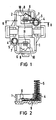
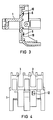
- the contact bridge support 1 has a rectangular recess 2, in which the switching magnetic part (not shown in more detail) can be fastened, as well as the towers 3 for receiving contact bridges (also not shown), and cylindrical cavities 4 diagonally opposite one another on the side of the recess 2, into the parts of spiral compression springs 5, which serve as back pressure springs for the contact bridge support in the electromagnetic switching device, are insertable.
- the coil compression springs 5 project with a part 6 of the last turn beyond the cylinder contour of the coil compression spring. These parts 6 are inserted when the springs are inserted into slots 7 which adjoin the cylindrical cavities 4, as is indicated by dashed lines in FIG. 1. You come into contact with the bottom surface 8.
- Transversely to the insertion slots 7 run parallel to the bottom surface 8 in the direction of the central part of the recess 2 grooves 9, into which the part 6 can be inserted when the spiral compression spring 7 is rotated.
- the part 6 comes into contact with an inclined surface 10 formed on the base surface 8, to which a groove or an undercut 11 connects.
- the part 6 thus latches in the groove 11 behind the inclined surface 10 after it has been raised by the inclined surface 10 when it is screwed in - shown in broken lines in FIG. 2.
- the groove 9 holds the part 6 practically on the bottom surface 8, so that the tension for the locking occurs when swiveling.
- the groove 9 and also the insertion slot 7 can be produced in a simple manner when the contact bridge carrier is pressed through an opening 12 into which a slide engages.
- the opening 12 can also be used for mechanically locking the part 6 after inserting the spiral compression spring into the cavities.
- the groove 9 is preferred executed in a width that corresponds to the spring wire diameter, so that good guidance of the spring is
Landscapes
- Physics & Mathematics (AREA)
- Electromagnetism (AREA)
- X-Ray Techniques (AREA)
- Switch Cases, Indication, And Locking (AREA)
- Mechanisms For Operating Contacts (AREA)
- Springs (AREA)
Description
- Die Erfindung bezieht sich auf ein elektrisches Gerät, insbesondere elektromagnetisches Schaltgerät, mit einer Anordnung zur Halterung von Spiraldruckfedern in zylinderförmigen Hohlräumen von Geräteteilen, insbesondere von Kontaktbrückenträgern von elektromagnetischen Schaltgeräten, bei der Teile der letzten Windung über die Zylinderkontur der Spiraldruckfeder hinausragend in an die Hohlräume angrenzende Einführschlitze einführbar und am Geräteteil gehalten sind.
- Bei einem bekannten elektrischen Gerät der obengenannten Art (DE-AS 23 31 870) werden die über die Zylinderkontur der Spiraldruckfeder hinausragenden Teile durch einen mit dem Gehäuseteil verbindbaren Block, beispielsweise den schaltenden Magnetteil, gehalten. Durch die Neuerung soll eine Anordnung der obengenannten Art dahingehend verbessert werden, daß die Rückdruckfedern auch ohne das zusätzliche Magnetteil in ihrer Lage gesichert sind und ohne daß hierzu aufwendige Zusatzeinrichtungen erforderlich sind. Dies wird auf einfache Weise dadurch erreicht, daß das der Zylinderkontur benachbarte Teil der letzten Windung in eine quer zum Einführschlitz verlaufende Nut eindrehbar und das freie Ende beim Eindrehen über eine Schrägfläche führbar und in eine angrenzende Nut einrastbar ist.
- Anhand der Zeichnung wird ein Ausführungsbeispiel gemäß der Erfindung beschrieben. Es zeigen:
- FIG 1
- eine Unteransicht auf einen Kontaktbrückenträger ohne eingesetzten schaltenden Magnetteil mit eingesetzten Rückdruckfedern,
- FIG 2
- eine Schnittdarstellung durch den Kontaktbrückenträger nach Fig. 1 gemäß der Linie II-II,
- FIG 3
- eine Seitenansicht im Schnitt durch den Kontaktbrückenträger und
- FIG 4
- eine Vorderansicht.
- Der Kontaktbrückenträger 1 besitzt eine quaderförmige Ausnehmung 2, in der der nicht näher dargestellte schaltende Magnetteil befestigt werden kann, sowie die Türme 3 zum Aufnehmen ebenfalls nicht dargestellter Kontaktbrücken, und seitlich der Ausnehmung 2 diagonal gegenüberliegende, zylinderförmige Hohlräume 4, in die Teile Spiraldruckfedern 5, die als Rückdruckfedern für den Kontaktbrückenträger im elektromagnetischen Schaltgerät dienen, einführbar sind. Die Spiraldruckfedern 5 ragen mit einem Teil 6 der letzten Windung über die Zylinderkontur der Spiraldruckfeder hinaus. Diese Teile 6 werden beim Einführen der Federn in Schlitze 7, die an die zylinderförmigen Hohlräume 4 angrenzen, eingeführt, wie dies gestrichelt in Fig. 1 angedeutet ist. Sie kommen hierbei mit der Bodenfläche 8 in Berührung. Quer zu den Einführschlitzen 7 verlaufen parallel zur Bodenfläche 8 in Richtung auf den Mittelteil der Ausnehmung 2 Nuten 9, in die das Teil 6 bei Verdrehen der Spiraldruckfeder 7 einführbar ist. Hierbei kommt das Teil 6 mit einer an der Bodenfläche 8 angeformten Schrägfläche 10 in Berührung, an die eine Nut oder ein Hinterschnitt 11 anschließt. Hinter der Schrägfläche 10 verrastet somit das Teil 6 in der Nut 11, nachdem es beim Eindrehen durch die Schrägfläche 10 angehoben wurde - in Fig. 2 gestrichelt dargestellt. Die Nut 9 hält das Teil 6 praktisch auf der Bodenfläche 8, so daß die Spannung für die Verrastung beim Einschwenken entsteht. Die Nut 9 und auch der Einführschlitz 7 kann beim Pressen des Kontaktbrückenträgers durch eine Öffnung 12, in die ein Schieber eingreift, auf einfache Weise hergestellt werden. Die Öffnung 12 kann auch zum maschinellen Verrasten des Teiles 6 nach Einführen der Spiraldruckfeder in die Hohlräume benutzt werden. Die Nut 9 wird vorzugsweise in einer Breite ausgeführt, die dem Federdrahtdurchmesser entspricht, so daß eine gute Führung der Feder auch nach dem Einrasten noch gewährleistet ist.
Claims (1)
- Elektrisches Gerät, insbesondere elektromagnetisches Schaltgerät, mit einer Anordnung zur Halterung von Spiraldruckfedern (5) in zylinderförmigen Hohlräumen (4) von Geräteteilen, insbesondere von Kontaktbrückenträgern von elektromagnetischen Schaltgeräten, bei der Teile (6) der letzten Windung über die Zylinderkontur der Spiraldruckfeder (5) hinausragend in an die Hohlräume (4) angrenzende Einführschlitze (7) einführbar und am Geräteteil gehalten sind, dadurch gekennzeichnet, daß das der Zylinderkontur benachbarte Teil (6) der letzten Windung in eine quer zum Einführschlitz (7) verlaufende Nut (9) eindrehbar und das freie Ende beim Eindrehen über eine Schrägfläche (10) führbar und in eine angrenzende Nut (11) einrastbar ist.
Priority Applications (1)
| Application Number | Priority Date | Filing Date | Title |
|---|---|---|---|
| AT87118406T ATE78361T1 (de) | 1986-12-24 | 1987-12-11 | Elektrisches geraet. |
Applications Claiming Priority (2)
| Application Number | Priority Date | Filing Date | Title |
|---|---|---|---|
| DE8634710U | 1986-12-24 | ||
| DE8634710U DE8634710U1 (de) | 1986-12-24 | 1986-12-24 | Elektrisches Gerät |
Publications (2)
| Publication Number | Publication Date |
|---|---|
| EP0276440A1 EP0276440A1 (de) | 1988-08-03 |
| EP0276440B1 true EP0276440B1 (de) | 1992-07-15 |
Family
ID=6801459
Family Applications (1)
| Application Number | Title | Priority Date | Filing Date |
|---|---|---|---|
| EP87118406A Expired - Lifetime EP0276440B1 (de) | 1986-12-24 | 1987-12-11 | Elektrisches Gerät |
Country Status (3)
| Country | Link |
|---|---|
| EP (1) | EP0276440B1 (de) |
| AT (1) | ATE78361T1 (de) |
| DE (2) | DE8634710U1 (de) |
Family Cites Families (3)
| Publication number | Priority date | Publication date | Assignee | Title |
|---|---|---|---|---|
| FR1311631A (fr) * | 1962-01-11 | 1962-12-07 | Ericsson Telefon Ab L M | Ressort de contact pour dispositif électrique de connexion |
| DE6751388U (de) * | 1968-08-01 | 1969-02-06 | Stotz Kontakt Gmbh | Schraubendruckfederhalterung. |
| JPS4942057Y1 (de) * | 1973-06-22 | 1974-11-18 |
-
1986
- 1986-12-24 DE DE8634710U patent/DE8634710U1/de not_active Expired
-
1987
- 1987-12-11 EP EP87118406A patent/EP0276440B1/de not_active Expired - Lifetime
- 1987-12-11 AT AT87118406T patent/ATE78361T1/de not_active IP Right Cessation
- 1987-12-11 DE DE8787118406T patent/DE3780439D1/de not_active Expired - Lifetime
Also Published As
| Publication number | Publication date |
|---|---|
| ATE78361T1 (de) | 1992-08-15 |
| DE8634710U1 (de) | 1987-02-19 |
| EP0276440A1 (de) | 1988-08-03 |
| DE3780439D1 (de) | 1992-08-20 |
Similar Documents
| Publication | Publication Date | Title |
|---|---|---|
| DE68912389T2 (de) | Biegsame Schaltung und Verbinder. | |
| DE2732519A1 (de) | Federleiste | |
| EP0024579B1 (de) | Fahrzeugleuchte mit einem aus einer Blechplatine hergestellten Lampenträger | |
| DE2005923C2 (de) | Anschluß- oder Verbindungsklemme | |
| EP0736929A1 (de) | Elektrisches Kontaktelement und Kunststoffgehäuse zur Aufnahme des Kontaktelementes | |
| DE3146739C2 (de) | Elektromagnetisches Schaltgerät | |
| EP0276440B1 (de) | Elektrisches Gerät | |
| EP0153591A2 (de) | Schraubenverbindung eines Steckerstiftes mit einem Leiterdraht | |
| DE29508610U1 (de) | Hilfsschalterbaustein schmaler Bauweise | |
| DE9212999U1 (de) | Vorrichtung zur Distanzüberbrückung des Lichtes einer Leuchtanzeige, insbesondere für Leuchtdioden... | |
| EP0106227A1 (de) | Schraubenlose Anschluss- oder Verbindungsklemme | |
| DE2622054C3 (de) | Elektromagnetisches Schaltgerät | |
| EP0043421A1 (de) | Koppelvorrichtung für in Stecker gefasste Lichtwellenleiter und Verfahren zur Herstellung der Vorrichtung | |
| DE2107464C3 (de) | Elektrischer Wippenschalter | |
| DE29917825U1 (de) | Verbindungselement mit Querverbindung | |
| EP0529146B1 (de) | Spule für den elektromagnetischen Antrieb eines Schaltgerätes | |
| DE19744754C1 (de) | Steckverbinder, insbesondere für Flachbandkabel | |
| EP0243647A1 (de) | Schutzschalter mit thermischer Ueberstromauslösung | |
| DE8134378U1 (de) | Elektromagnetisches Schaltgerät | |
| DE19720196A1 (de) | Messwerk | |
| DE3619372C2 (de) | ||
| EP0565998B1 (de) | Vorrichtung zur Klemmkontaktierung von elektrischen Bauelementen | |
| DE1185662B (de) | Loetoesenleiste | |
| DE1954766C (de) | Kassettensystem für eine Magnet anordnung fur elektrische Steuervorrich tungen | |
| DE29914020U1 (de) | Montageclip für einen Querverbindungskamm und Querverbindungseinheit |
Legal Events
| Date | Code | Title | Description |
|---|---|---|---|
| PUAI | Public reference made under article 153(3) epc to a published international application that has entered the european phase |
Free format text: ORIGINAL CODE: 0009012 |
|
| AK | Designated contracting states |
Kind code of ref document: A1 Designated state(s): AT CH DE FR GB IT LI SE |
|
| 17P | Request for examination filed |
Effective date: 19890126 |
|
| 17Q | First examination report despatched |
Effective date: 19911206 |
|
| GRAA | (expected) grant |
Free format text: ORIGINAL CODE: 0009210 |
|
| AK | Designated contracting states |
Kind code of ref document: B1 Designated state(s): AT CH DE FR GB IT LI SE |
|
| REF | Corresponds to: |
Ref document number: 78361 Country of ref document: AT Date of ref document: 19920815 Kind code of ref document: T |
|
| REF | Corresponds to: |
Ref document number: 3780439 Country of ref document: DE Date of ref document: 19920820 |
|
| ET | Fr: translation filed | ||
| ITF | It: translation for a ep patent filed | ||
| GBT | Gb: translation of ep patent filed (gb section 77(6)(a)/1977) | ||
| PLBE | No opposition filed within time limit |
Free format text: ORIGINAL CODE: 0009261 |
|
| STAA | Information on the status of an ep patent application or granted ep patent |
Free format text: STATUS: NO OPPOSITION FILED WITHIN TIME LIMIT |
|
| 26N | No opposition filed | ||
| PGFP | Annual fee paid to national office [announced via postgrant information from national office to epo] |
Ref country code: AT Payment date: 19931124 Year of fee payment: 7 |
|
| PGFP | Annual fee paid to national office [announced via postgrant information from national office to epo] |
Ref country code: SE Payment date: 19931222 Year of fee payment: 7 |
|
| PGFP | Annual fee paid to national office [announced via postgrant information from national office to epo] |
Ref country code: CH Payment date: 19940321 Year of fee payment: 7 |
|
| PGFP | Annual fee paid to national office [announced via postgrant information from national office to epo] |
Ref country code: GB Payment date: 19941114 Year of fee payment: 8 |
|
| PG25 | Lapsed in a contracting state [announced via postgrant information from national office to epo] |
Ref country code: AT Effective date: 19941211 |
|
| PG25 | Lapsed in a contracting state [announced via postgrant information from national office to epo] |
Ref country code: SE Effective date: 19941212 |
|
| PG25 | Lapsed in a contracting state [announced via postgrant information from national office to epo] |
Ref country code: LI Effective date: 19941231 Ref country code: CH Effective date: 19941231 |
|
| EAL | Se: european patent in force in sweden |
Ref document number: 87118406.5 |
|
| REG | Reference to a national code |
Ref country code: CH Ref legal event code: PL |
|
| EUG | Se: european patent has lapsed |
Ref document number: 87118406.5 |
|
| PG25 | Lapsed in a contracting state [announced via postgrant information from national office to epo] |
Ref country code: GB Effective date: 19951211 |
|
| GBPC | Gb: european patent ceased through non-payment of renewal fee |
Effective date: 19951211 |
|
| PGFP | Annual fee paid to national office [announced via postgrant information from national office to epo] |
Ref country code: FR Payment date: 20001222 Year of fee payment: 14 |
|
| PGFP | Annual fee paid to national office [announced via postgrant information from national office to epo] |
Ref country code: DE Payment date: 20010219 Year of fee payment: 14 |
|
| PG25 | Lapsed in a contracting state [announced via postgrant information from national office to epo] |
Ref country code: DE Free format text: LAPSE BECAUSE OF NON-PAYMENT OF DUE FEES Effective date: 20020702 |
|
| PG25 | Lapsed in a contracting state [announced via postgrant information from national office to epo] |
Ref country code: FR Free format text: LAPSE BECAUSE OF NON-PAYMENT OF DUE FEES Effective date: 20020830 |
|
| REG | Reference to a national code |
Ref country code: FR Ref legal event code: ST |
|
| PG25 | Lapsed in a contracting state [announced via postgrant information from national office to epo] |
Ref country code: IT Free format text: LAPSE BECAUSE OF NON-PAYMENT OF DUE FEES;WARNING: LAPSES OF ITALIAN PATENTS WITH EFFECTIVE DATE BEFORE 2007 MAY HAVE OCCURRED AT ANY TIME BEFORE 2007. THE CORRECT EFFECTIVE DATE MAY BE DIFFERENT FROM THE ONE RECORDED. Effective date: 20051211 |