EP0275552B1 - Künstlicher gelenkloser Fuss - Google Patents
Künstlicher gelenkloser Fuss Download PDFInfo
- Publication number
- EP0275552B1 EP0275552B1 EP87119299A EP87119299A EP0275552B1 EP 0275552 B1 EP0275552 B1 EP 0275552B1 EP 87119299 A EP87119299 A EP 87119299A EP 87119299 A EP87119299 A EP 87119299A EP 0275552 B1 EP0275552 B1 EP 0275552B1
- Authority
- EP
- European Patent Office
- Prior art keywords
- wooden core
- foot
- core
- forming
- connection surface
- Prior art date
- Legal status (The legal status is an assumption and is not a legal conclusion. Google has not performed a legal analysis and makes no representation as to the accuracy of the status listed.)
- Expired - Lifetime
Links
Images
Classifications
-
- A—HUMAN NECESSITIES
- A61—MEDICAL OR VETERINARY SCIENCE; HYGIENE
- A61F—FILTERS IMPLANTABLE INTO BLOOD VESSELS; PROSTHESES; DEVICES PROVIDING PATENCY TO, OR PREVENTING COLLAPSING OF, TUBULAR STRUCTURES OF THE BODY, e.g. STENTS; ORTHOPAEDIC, NURSING OR CONTRACEPTIVE DEVICES; FOMENTATION; TREATMENT OR PROTECTION OF EYES OR EARS; BANDAGES, DRESSINGS OR ABSORBENT PADS; FIRST-AID KITS
- A61F2/00—Filters implantable into blood vessels; Prostheses, i.e. artificial substitutes or replacements for parts of the body; Appliances for connecting them with the body; Devices providing patency to, or preventing collapsing of, tubular structures of the body, e.g. stents
- A61F2/50—Prostheses not implantable in the body
- A61F2/60—Artificial legs or feet or parts thereof
- A61F2/66—Feet; Ankle joints
-
- A—HUMAN NECESSITIES
- A21—BAKING; EDIBLE DOUGHS
- A21B—BAKERS' OVENS; MACHINES OR EQUIPMENT FOR BAKING
- A21B3/00—Parts or accessories of ovens
- A21B3/04—Air-treatment devices for ovens, e.g. regulating humidity
-
- A—HUMAN NECESSITIES
- A23—FOODS OR FOODSTUFFS; TREATMENT THEREOF, NOT COVERED BY OTHER CLASSES
- A23L—FOODS, FOODSTUFFS OR NON-ALCOHOLIC BEVERAGES, NOT OTHERWISE PROVIDED FOR; PREPARATION OR TREATMENT THEREOF
- A23L5/00—Preparation or treatment of foods or foodstuffs, in general; Food or foodstuffs obtained thereby; Materials therefor
- A23L5/10—General methods of cooking foods, e.g. by roasting or frying
- A23L5/13—General methods of cooking foods, e.g. by roasting or frying using water or steam
-
- A—HUMAN NECESSITIES
- A47—FURNITURE; DOMESTIC ARTICLES OR APPLIANCES; COFFEE MILLS; SPICE MILLS; SUCTION CLEANERS IN GENERAL
- A47J—KITCHEN EQUIPMENT; COFFEE MILLS; SPICE MILLS; APPARATUS FOR MAKING BEVERAGES
- A47J27/00—Cooking-vessels
- A47J27/14—Cooking-vessels for use in hotels, restaurants, or canteens
- A47J27/16—Cooking-vessels for use in hotels, restaurants, or canteens heated by steam
Definitions
- the invention relates to an artificial jointless foot with an incompressible wooden core forming an upper connection surface and with elastic plastic materials connected to the core for forming the foot shape and ensuring a flexible rolling process, the wooden core forming a dorsal stop on its connection surface for an adapter which can be connected to it .
- Such articulated feet have been known for a long time (see e.g. EP-A 0 122 372) and are frequently used. Thanks to a clever arrangement of flexible materials on the wooden core, the jointless feet can be designed in such a way that they cannot be inferior to an articulated foot in terms of walking comfort and can even surpass it.
- the wood core of such articulated feet should be made from the lightest possible wood.
- the light and, moreover, inexpensive wood can perform all the functions of the core of such an articulated foot, but has the disadvantage that due to its softness a strong wear sets in on its connecting surface in the region of the dorsal stop, which occurs due to the occurrence of each rolling process
- the surface is stressed by a metal adapter connected to the foot. When unrolling, the adapter resting on the connection surface presses with its front edge onto the connection surface of the wood core.
- the connection surface at this point ie at the point of the dorsal stop, is deformed very quickly, as a result of which the strength of the connection with the adapter is no longer guaranteed and undesirable play movements of the foot can occur.
- the screw connection of the adapter can break, making the entire prosthetic foot unusable and prone to accidents.
- the invention has for its object to design an articulated foot of the type mentioned so that wear of the wood core in the area of the dorsal stop - even when using a relatively soft and light wood for the wood core - is effectively avoided.
- the wood core in the region of the dorsal stop has an upwardly open recess which is filled with a thermosetting casting resin, the surface of which is flush with the connecting surface.
- thermosetting cast resin is provided with a filler.
- thermosetting resin creates a secure, firm connection with the wooden core and can be filled in in a simple manner so that its surface is exactly aligned with the connection surface. If necessary, a subsequent joint processing of the connection surface can be carried out for this purpose.
- the artificial jointless foot according to the invention can therefore be constructed with an inexpensive, lightweight wooden core due to the simple and inexpensive measure described.
- a filled casting resin is preferably used as the thermosetting casting resin, slate powder, glass, sand or the like being suitable as the filler.
- the filler not only reduces the price of the casting resin used, it also reduces the exothermic reaction that regularly occurs when the casting resin hardens and increases the compressive strength.
- a two-component casting resin of which one component acts as a hardener, is regularly used as the curing casting resin.
- a casting resin that hardens under the action of ultraviolet radiation is also possible.
- the foot shown in the drawing consists essentially of a wooden core 1, a heel wedge 2 arranged in the heel area of the foot, an inner foot 3 connected to the front of the wooden core 1 and the heel wedge 2, and a skin-forming covering layer 4.
- the core 1 forms an upper connection surface 5, on which an adapter for connection to an artificial leg is placed.
- a hole 6 is used to fasten the adapter, which extends perpendicularly to the connecting surface 5 in the wooden core 1 and at the lower edge of the wooden core 1 it is step-shaped continues.
- the bore 6 serves to receive the shaft and the head of a fastening screw.
- the adapter (not shown) lies with its front edge at a point on the connection surface 5 which forms a dorsal stop 7.
- the wooden core 1 is hollowed out on the surface and forms an elongated hole 8 which is open at the top.
- thermosetting resin 9 is filled, which is mixed with a slate flour, with glass dust or sand as a filler.
- the surface of the resin 9 is aligned with the pad 5, so that a common flat surface is formed.
- the casting resin penetrates into the wooden pores of the recess 8 and firmly connects to the wooden core 1.
- the surface of the casting resin 9 is not damaged by the load on the adapter.
- the strength of the connection of the casting resin 9 with the wooden core 1 is not affected by the load.
- the dorsal stop 7 is therefore suitable for any load caused by the adapter.
Landscapes
- Health & Medical Sciences (AREA)
- Engineering & Computer Science (AREA)
- Food Science & Technology (AREA)
- Life Sciences & Earth Sciences (AREA)
- Transplantation (AREA)
- Public Health (AREA)
- Orthopedic Medicine & Surgery (AREA)
- Heart & Thoracic Surgery (AREA)
- Vascular Medicine (AREA)
- Oral & Maxillofacial Surgery (AREA)
- Animal Behavior & Ethology (AREA)
- General Health & Medical Sciences (AREA)
- Cardiology (AREA)
- Veterinary Medicine (AREA)
- Biomedical Technology (AREA)
- Nutrition Science (AREA)
- Chemical & Material Sciences (AREA)
- Polymers & Plastics (AREA)
- Prostheses (AREA)
- Floor Finish (AREA)
- Golf Clubs (AREA)
- Casting Or Compression Moulding Of Plastics Or The Like (AREA)
- Materials For Medical Uses (AREA)
- Casings For Electric Apparatus (AREA)
Description
- Die Erfindung betrifft einen künstlichen gelenklosen Fuß mit einem eine obere Anschlußfläche bildenden inkompressiblen Holzkem und mit elastischen, mit dem Kem verbundenen Kunststoffmaterialien zur Ausbildung der Fußform und Gewährleistung eines flexiblen Abrollvorgangs, wobei der Holzkem auf seiner Anschlußfläche einen dorsalen Anschlag für einen mit ihm verbindbaren Adapter bildet.
- Derartige gelenklose Füße sind seit langer Zeit bekannt (s. z.B. EP-A 0 122 372) und werden häufig verwendet. Die gelenklosen Füße lassen sich aufgrund einer geschickten Anordnung von flexiblen Materialien an dem Holzkem so ausbilden, daß sie einem Gelenkfuß im Gehkomfort nicht nachstehen und ihn sogar übertreffen können.
- Die Holzkeme derartiger gelenkloser Füße sollten aus möglichst leichtem Holz hergestellt werden. Das leichte und darüber hinaus preiswerte Holz kann an sich alle Funktionen des Kems eines derartigen gelenklosen Fußes erfüllen, weist jedoch den Nachteil auf, daß an seiner Anschlußfläche im Bereich des dorsalen Anschlages aufgrund seiner Weichheit eine starke Abnutzung einsetzt, die aufgrund der bei jedem Abrollvorgang auftretenden Belastung der Oberfläche durch einen mit dem Fuß verbundenen Metall-Adapter entsteht. Beim Abrollen drückt der auf der Anschlußfläche aufliegende Adapter mit seiner Vorderkante auf die Anschlußfläche des Holzkems. Bei der Verwendung von leichtem Holz wird die Anschlußfläche an dieser Stelle, also an der Stelle des dorsalen Anschlags, sehr bald deformiert, wodurch die Festigkeit der Verbindung mit dem Adapter nicht mehr gewähdeistet ist und unerwünschte Spielbewegungen des Fußes auftreten können. Darüber hinaus kann sogar die Verschraubung des Adapters brechen, so daß die gesamte Fußprothese unbrauchbar und unfallträchtig wird.
- Diese Beschädigungsmöglichkeit hat den Einsatz von teurem, harten Holz notwendig gemacht, das allerdings das Gewicht der Fußprothese wesentlich erhöht hat.
- Es ist bereits bei internen Versuchen der Anmelderin versucht worden, den Einsatz von teurem und schwerem Holz dadurch zu vermeiden, daß der leichte Holzkem an seiner Anschlußfläche im Bereich des dorsalen Anschlags verstärkt worden ist. Eine aufgesetzte Metallplatte führt jedoch zu einer unerwünschten gleitenden Bewegung des Adapters auf der Anschlußfläche. Es ist femer versucht worden, die Oberfläche des Holzkems an der Stelle des dorsalen Anschlags durch einen Hartholzeinsatz zu ersetzen. Es hat sich jedoch gezeigt, daß eine stabile Verbindung des Hartholzeinsatzes mit dem Holzkem durch Verklebung o. ä. aufgrund der starken Belastung nicht möglich ist.
- Der Erfindung liegt die Aufgabe zugrunde, einen künstlichen gelenklosen Fuß der eingangs erwähnten Art so auszubilden, daß eine Abnutzung des Holzkems im Bereich des dorsalen Anschlags - auch bei der Verwendung von einem relativ weichen und leichten Holz für den Holzkem- wirksam vermieden wird.
- Diese Aufgabe wird erfindungsgemäß dadurch gelöst, daß der Holzkern im Bereich des dorsalen Anschlags eine nach oben offene Ausnehmung aufweist, die mit einem duroplastischen Gießharz gefüllt ist, dessen Oberfläche mit der Anschlußfläche fluchtet.
- In einer bevorzugten Ausführungsform ist das duroplastische Gießharz mit einem Füllstoff versehen.
- In überraschend einfacher Weise läßt sich die Abnutzung des Holzkerns im Bereich des dorsalen Anschlags dadurch vermeiden, daß in die Ausnehmung des Holzkerns duroplastisches Gießharz eingefüllt wird. Das duroplastische Gießharz stellt eine sichere feste Verbindung mit dem Holzkern her und läßt sich in einfacher Weise so einfüllen, daß seine Oberfläche mit der Anschlußfläche exakt fluchtet. Gegebenenfalls kann hierzu eine anschließende gemeinsame Bearbeitung der Anschlußfläche vorgenommen werden.
- Versuche haben gezeigt, daß trotz extremer Belastung der Oberfläche des Gießharzes dieses fest in dem Holzkem verankert ist und keine Abnutzungserscheinungen zeigt.
- Der erfindungsgemäße künstliche gelenklose Fuß kann daher aufgrund der geschilderten einfachen und preiswerten Maßnahme mit einem preiswerten, leichten Holzkern aufgebaut werden.
- Als duroplastisches Gießharz wird vorzugsweise ein gefülltes Gießharz verwendet, wobei als Füllstoff Schiefermehl, Glas, Sand o. dgl. in Frage kommt. Durch den Füllstoff wird nicht nur der Preis für das verwendete Gießharz gesenkt, sondern auch die beim Aushärten des Gießharzes regelmä- ßig auftretende exotherme Reaktion gemindert und die Druckfestigkeit erhöht.
- Als aushärtendes Gießharz wird regelmäßig ein Zwei-Komponenten-Gießharz, wovon eine Komponente als Härter wirkt, verwendet werden. Es ist aber auch möglich, ein Gießharz zu verwenden, daß unter Einwirkung von ultravioletter Strahlung aushärtet.
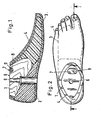
- Die Erfindung soll im folgenden anhand eines in der Zeichnung dargestellten Ausführungsbeispiels näher erläutert werden. Es zeigen:
- Figur 1 - einen Längsschnitt durch einen künstlichen gelenklosen Fuß
- Figur 2 - eine Draufsicht auf den Fuß gemäß Figur 1.
- Der in der Zeichnung dargestellte Fuß besteht im wesentlichen aus einem Holzkern 1, einem im Fersenbereich des Fußes angeordneten Fersenkeil 2, einem an die Vorderseite des Holzkems 1 und des Fersenkeils 2 angeschlossenen Innenfuß 3 sowie einer hautbildenden Umhüllungsschicht 4. Der Kem 1 bildet eine obere Anschlußfläche 5, auf die ein Adapter zur Verbindung mit einem künstlichen Bein aufgesetzt wird. Zur Befestigung des Adapters dient eine Bohrung 6, die sich senkrecht zur Anschlußfläche 5 in den Holzkem 1 erstreckt und sich am unteren Rand des Holzkems 1 stufenförmig erweitert. Die Bohrung 6 dient zur Aufnahme des Schaftes und des Kopfes einer Befestigungsschraube.
- Der (nicht dargestellte) Adapter liegt mit seiner vorderen Kante an einer Stelle der Anschlußfläche 5 auf, die einen dorsalen Anschlag 7 bildet. Im Bereich des dorsalen Anschlags 7 ist der Holzkern 1 an der Oberfläche ausgehöhlt und bildet eine nach oben offene, langlochförmige Ausnehmung 8.
- In die Ausnehmung 8 ist ein duroplastisches Gießharz 9 eingefüllt, das mit einem Schiefermehl, mit Glasstaub oder Sand als Füllstoff versetzt ist. Die Oberfläche des Gießharzes 9 fluchtet mit der Anschlußfläche 5, so daß eine gemeinsame ebene Oberfläche entsteht.
- Das Gießharz dringt in die Holzporen der Ausnehmung 8 ein und verbindet sich fest mit dem Holzkern 1. Die Oberfläche des Gießharzes 9 wird durch die Belastung des Adapters nicht beschädigt. Die Festigkeit der Verbindung des Gießharzes 9 mit dem Holzkern 1 wird durch die Belastung nicht beeinträchtigt.
- Unabhängig von den Eigenschaften des Holzkems 1 ist der dorsale Anschlag 7 daher für jede Belastung durch den Adapter geeignet.
Claims (2)
Priority Applications (1)
| Application Number | Priority Date | Filing Date | Title |
|---|---|---|---|
| AT87119299T ATE58053T1 (de) | 1986-12-29 | 1987-12-29 | Kuenstlicher gelenkloser fuss. |
Applications Claiming Priority (2)
| Application Number | Priority Date | Filing Date | Title |
|---|---|---|---|
| DE3644612A DE3644612C1 (de) | 1986-12-29 | 1986-12-29 | Kuenstlicher gelenkloser Fuss |
| DE3644612 | 1986-12-29 |
Publications (2)
| Publication Number | Publication Date |
|---|---|
| EP0275552A1 EP0275552A1 (de) | 1988-07-27 |
| EP0275552B1 true EP0275552B1 (de) | 1990-11-07 |
Family
ID=6317324
Family Applications (1)
| Application Number | Title | Priority Date | Filing Date |
|---|---|---|---|
| EP87119299A Expired - Lifetime EP0275552B1 (de) | 1986-12-29 | 1987-12-29 | Künstlicher gelenkloser Fuss |
Country Status (11)
| Country | Link |
|---|---|
| US (1) | US5037443A (de) |
| EP (1) | EP0275552B1 (de) |
| JP (1) | JPS63260550A (de) |
| CN (1) | CN1011856B (de) |
| AT (1) | ATE58053T1 (de) |
| BR (1) | BR8707112A (de) |
| CA (1) | CA1290101C (de) |
| DD (1) | DD273196A5 (de) |
| DE (2) | DE3644612C1 (de) |
| ES (1) | ES2018673B3 (de) |
| TR (1) | TR23106A (de) |
Families Citing this family (5)
| Publication number | Priority date | Publication date | Assignee | Title |
|---|---|---|---|---|
| RU2124334C1 (ru) * | 1997-10-29 | 1999-01-10 | Реутовский экспериментальный завод резинотехнических изделий | Способ изготовления протеза стопы |
| US6086601A (en) * | 1998-04-29 | 2000-07-11 | Yoon; Inbae | Instrument and method for suturing anatomical tissue and tying suture material |
| RU2162674C2 (ru) * | 1999-05-17 | 2001-02-10 | Открытое акционерное общество "Ракетно-космическая корпорация "Энергия" им. С.П. Королева" | Пневмостопа протеза нижней конечности |
| DE10213466A1 (de) | 2002-03-26 | 2003-10-09 | Rheinmetall W & M Gmbh | Geschoßkörper |
| US8747485B1 (en) | 2011-10-04 | 2014-06-10 | Rene Nunez | Artificial ankle joint |
Family Cites Families (7)
| Publication number | Priority date | Publication date | Assignee | Title |
|---|---|---|---|---|
| US757287A (en) * | 1903-11-20 | 1904-04-12 | Lee Duggan | Artificial leg. |
| US817340A (en) * | 1905-03-01 | 1906-04-10 | Rudolf Rosenkranz | Artificial limb. |
| DE326131C (de) * | 1919-07-05 | 1920-09-24 | Bernhard Conrad | Kuenstlicher Fuss |
| US3098239A (en) * | 1961-01-18 | 1963-07-23 | Nader Hugo Otto Max | Prosthetic foot |
| DE2442441C3 (de) * | 1974-09-05 | 1978-07-06 | Otto Bock Orthopaedische Industrie Kg, 3428 Duderstadt | Kunstfuß mit Knöchelgelenk |
| DE8307982U1 (de) * | 1983-03-18 | 1987-01-02 | Otto Bock, Orthopaedische Industrie Kg, 3428 Duderstadt | Künstlicher Fuß |
| US4652266A (en) * | 1986-03-07 | 1987-03-24 | Kingsley Mfg. Co. | Molded elastomeric prosthetic foot having energy-storing articulated keel |
-
1986
- 1986-12-29 DE DE3644612A patent/DE3644612C1/de not_active Expired
-
1987
- 1987-05-27 US US07/054,446 patent/US5037443A/en not_active Expired - Fee Related
- 1987-12-23 TR TR17/88A patent/TR23106A/xx unknown
- 1987-12-28 JP JP62336728A patent/JPS63260550A/ja active Pending
- 1987-12-29 EP EP87119299A patent/EP0275552B1/de not_active Expired - Lifetime
- 1987-12-29 CN CN87105981A patent/CN1011856B/zh not_active Expired
- 1987-12-29 AT AT87119299T patent/ATE58053T1/de not_active IP Right Cessation
- 1987-12-29 ES ES87119299T patent/ES2018673B3/es not_active Expired - Lifetime
- 1987-12-29 DD DD87311668A patent/DD273196A5/de unknown
- 1987-12-29 BR BR8707112A patent/BR8707112A/pt unknown
- 1987-12-29 CA CA000555507A patent/CA1290101C/en not_active Expired - Lifetime
- 1987-12-29 DE DE8787119299T patent/DE3766094D1/de not_active Expired - Lifetime
Also Published As
| Publication number | Publication date |
|---|---|
| DD273196A5 (de) | 1989-11-08 |
| DE3644612C1 (de) | 1988-07-14 |
| CN1011856B (zh) | 1991-03-06 |
| ATE58053T1 (de) | 1990-11-15 |
| ES2018673B3 (es) | 1991-05-01 |
| DE3766094D1 (de) | 1990-12-13 |
| EP0275552A1 (de) | 1988-07-27 |
| JPS63260550A (ja) | 1988-10-27 |
| TR23106A (tr) | 1989-03-30 |
| US5037443A (en) | 1991-08-06 |
| CA1290101C (en) | 1991-10-08 |
| BR8707112A (pt) | 1988-08-02 |
| CN87105981A (zh) | 1988-08-31 |
Similar Documents
| Publication | Publication Date | Title |
|---|---|---|
| EP0562241A1 (de) | Künstlicher Fuss | |
| EP0407650B1 (de) | Kunstfuss für eine Beinprothese | |
| DE2306552B2 (de) | Gelenkendoprothese | |
| EP0401864A1 (de) | Gelenkloser Prothesenfuss | |
| DE2344569B2 (de) | Schultergelenk-endoprothese | |
| EP0955021A1 (de) | Satz von Bandscheiben-Endoprothesen | |
| DE8307982U1 (de) | Künstlicher Fuß | |
| AT398906B (de) | Stossdämpfer zur befestigung von skibindungen | |
| DE3935129A1 (de) | Prothese fuer beinamputation und verfahren zu ihrer herstellung | |
| WO2001044613A1 (de) | Leichtbauplatte | |
| DE3644612C1 (de) | Kuenstlicher gelenkloser Fuss | |
| DE2241971A1 (de) | Kuenstlicher fuss | |
| EP0061707A1 (de) | Vorgefertigte Abdeckung für eine Treppenstufe | |
| DE8632856U1 (de) | Elastische Platte, insbesondere Bodenplatte | |
| WO2000079074A1 (de) | Holzfussboden | |
| DE69604323T2 (de) | Schuh mit Vorlageeinstellung des Schaftes | |
| DE8318360U1 (de) | Zementfrei implantierbare Prothese mit Rasterprofilierung | |
| DE8634786U1 (de) | Künstlicher gelenkloser Fuß | |
| DE19746549C2 (de) | Belagelement | |
| EP0080456B1 (de) | Schuhsohle, sowie Form und Verfahren zur Herstellung derselben | |
| DE7437814U (de) | Leichtplatte, insbesondere baustoffplatte | |
| DE7920601U1 (de) | Keramische einbau-kuechenspuele | |
| AT392214B (de) | Anordnung zur befestigung einer skibindung | |
| DE955776C (de) | Eisenbahnschwelle | |
| DE7534175U (de) | Vorgefertigte elastische bodenbelagbahn oder -platte fuer sportstaetten o.dgl. |
Legal Events
| Date | Code | Title | Description |
|---|---|---|---|
| PUAI | Public reference made under article 153(3) epc to a published international application that has entered the european phase |
Free format text: ORIGINAL CODE: 0009012 |
|
| AK | Designated contracting states |
Kind code of ref document: A1 Designated state(s): AT BE CH DE ES FR GB GR IT LI LU NL SE |
|
| 17P | Request for examination filed |
Effective date: 19880723 |
|
| 17Q | First examination report despatched |
Effective date: 19900201 |
|
| GRAA | (expected) grant |
Free format text: ORIGINAL CODE: 0009210 |
|
| AK | Designated contracting states |
Kind code of ref document: B1 Designated state(s): AT BE CH DE ES FR GB GR IT LI LU NL SE |
|
| PG25 | Lapsed in a contracting state [announced via postgrant information from national office to epo] |
Ref country code: GR Free format text: LAPSE BECAUSE OF FAILURE TO SUBMIT A TRANSLATION OF THE DESCRIPTION OR TO PAY THE FEE WITHIN THE PRESCRIBED TIME-LIMIT Effective date: 19901107 |
|
| REF | Corresponds to: |
Ref document number: 58053 Country of ref document: AT Date of ref document: 19901115 Kind code of ref document: T |
|
| GBT | Gb: translation of ep patent filed (gb section 77(6)(a)/1977) | ||
| REF | Corresponds to: |
Ref document number: 3766094 Country of ref document: DE Date of ref document: 19901213 |
|
| ET | Fr: translation filed | ||
| PG25 | Lapsed in a contracting state [announced via postgrant information from national office to epo] |
Ref country code: LU Free format text: LAPSE BECAUSE OF NON-PAYMENT OF DUE FEES Effective date: 19901231 |
|
| ITF | It: translation for a ep patent filed | ||
| PLBE | No opposition filed within time limit |
Free format text: ORIGINAL CODE: 0009261 |
|
| STAA | Information on the status of an ep patent application or granted ep patent |
Free format text: STATUS: NO OPPOSITION FILED WITHIN TIME LIMIT |
|
| 26N | No opposition filed | ||
| PGFP | Annual fee paid to national office [announced via postgrant information from national office to epo] |
Ref country code: SE Payment date: 19911031 Year of fee payment: 5 |
|
| PGFP | Annual fee paid to national office [announced via postgrant information from national office to epo] |
Ref country code: FR Payment date: 19911122 Year of fee payment: 5 |
|
| PGFP | Annual fee paid to national office [announced via postgrant information from national office to epo] |
Ref country code: BE Payment date: 19911129 Year of fee payment: 5 |
|
| PGFP | Annual fee paid to national office [announced via postgrant information from national office to epo] |
Ref country code: GB Payment date: 19911217 Year of fee payment: 5 |
|
| PGFP | Annual fee paid to national office [announced via postgrant information from national office to epo] |
Ref country code: CH Payment date: 19911219 Year of fee payment: 5 |
|
| PGFP | Annual fee paid to national office [announced via postgrant information from national office to epo] |
Ref country code: AT Payment date: 19911230 Year of fee payment: 5 |
|
| ITTA | It: last paid annual fee | ||
| PGFP | Annual fee paid to national office [announced via postgrant information from national office to epo] |
Ref country code: NL Payment date: 19911231 Year of fee payment: 5 |
|
| PGFP | Annual fee paid to national office [announced via postgrant information from national office to epo] |
Ref country code: DE Payment date: 19920115 Year of fee payment: 5 |
|
| PGFP | Annual fee paid to national office [announced via postgrant information from national office to epo] |
Ref country code: ES Payment date: 19921211 Year of fee payment: 6 |
|
| PG25 | Lapsed in a contracting state [announced via postgrant information from national office to epo] |
Ref country code: GB Effective date: 19921229 Ref country code: AT Effective date: 19921229 |
|
| PG25 | Lapsed in a contracting state [announced via postgrant information from national office to epo] |
Ref country code: SE Effective date: 19921230 |
|
| PG25 | Lapsed in a contracting state [announced via postgrant information from national office to epo] |
Ref country code: LI Effective date: 19921231 Ref country code: CH Effective date: 19921231 Ref country code: BE Effective date: 19921231 |
|
| BERE | Be: lapsed |
Owner name: OTTO BOCK ORTHOPADISCHE INDUSTRIE BESITZ- UND VER Effective date: 19921231 |
|
| PG25 | Lapsed in a contracting state [announced via postgrant information from national office to epo] |
Ref country code: NL Effective date: 19930701 |
|
| NLV4 | Nl: lapsed or anulled due to non-payment of the annual fee | ||
| GBPC | Gb: european patent ceased through non-payment of renewal fee |
Effective date: 19921229 |
|
| PG25 | Lapsed in a contracting state [announced via postgrant information from national office to epo] |
Ref country code: FR Effective date: 19930831 |
|
| REG | Reference to a national code |
Ref country code: CH Ref legal event code: PL |
|
| PG25 | Lapsed in a contracting state [announced via postgrant information from national office to epo] |
Ref country code: DE Effective date: 19930901 |
|
| REG | Reference to a national code |
Ref country code: FR Ref legal event code: ST |
|
| PG25 | Lapsed in a contracting state [announced via postgrant information from national office to epo] |
Ref country code: ES Free format text: LAPSE BECAUSE OF NON-PAYMENT OF DUE FEES Effective date: 19941230 |
|
| EUG | Se: european patent has lapsed |
Ref document number: 87119299.3 Effective date: 19930709 |
|
| REG | Reference to a national code |
Ref country code: ES Ref legal event code: FD2A Effective date: 19950112 |
|
| PG25 | Lapsed in a contracting state [announced via postgrant information from national office to epo] |
Ref country code: IT Free format text: LAPSE BECAUSE OF NON-PAYMENT OF DUE FEES;WARNING: LAPSES OF ITALIAN PATENTS WITH EFFECTIVE DATE BEFORE 2007 MAY HAVE OCCURRED AT ANY TIME BEFORE 2007. THE CORRECT EFFECTIVE DATE MAY BE DIFFERENT FROM THE ONE RECORDED. Effective date: 20051229 |