EP0270935A2 - Motorhaube und Gehäuse für Nass-/Trockensauger - Google Patents
Motorhaube und Gehäuse für Nass-/Trockensauger Download PDFInfo
- Publication number
- EP0270935A2 EP0270935A2 EP87117458A EP87117458A EP0270935A2 EP 0270935 A2 EP0270935 A2 EP 0270935A2 EP 87117458 A EP87117458 A EP 87117458A EP 87117458 A EP87117458 A EP 87117458A EP 0270935 A2 EP0270935 A2 EP 0270935A2
- Authority
- EP
- European Patent Office
- Prior art keywords
- motor
- cover
- cap
- box
- assembly
- Prior art date
- Legal status (The legal status is an assumption and is not a legal conclusion. Google has not performed a legal analysis and makes no representation as to the accuracy of the status listed.)
- Withdrawn
Links
- 238000001816 cooling Methods 0.000 claims abstract description 15
- 230000015572 biosynthetic process Effects 0.000 claims description 5
- 238000005755 formation reaction Methods 0.000 claims description 5
- 230000001105 regulatory effect Effects 0.000 claims description 2
- 239000002991 molded plastic Substances 0.000 abstract 2
- 238000007689 inspection Methods 0.000 abstract 1
- 238000010276 construction Methods 0.000 description 7
- 238000005192 partition Methods 0.000 description 6
- 239000004020 conductor Substances 0.000 description 5
- 239000000463 material Substances 0.000 description 4
- RNFJDJUURJAICM-UHFFFAOYSA-N 2,2,4,4,6,6-hexaphenoxy-1,3,5-triaza-2$l^{5},4$l^{5},6$l^{5}-triphosphacyclohexa-1,3,5-triene Chemical compound N=1P(OC=2C=CC=CC=2)(OC=2C=CC=CC=2)=NP(OC=2C=CC=CC=2)(OC=2C=CC=CC=2)=NP=1(OC=1C=CC=CC=1)OC1=CC=CC=C1 RNFJDJUURJAICM-UHFFFAOYSA-N 0.000 description 3
- 230000000994 depressogenic effect Effects 0.000 description 3
- 239000003063 flame retardant Substances 0.000 description 3
- 235000012771 pancakes Nutrition 0.000 description 2
- OKTJSMMVPCPJKN-UHFFFAOYSA-N Carbon Chemical compound [C] OKTJSMMVPCPJKN-UHFFFAOYSA-N 0.000 description 1
- 230000000903 blocking effect Effects 0.000 description 1
- 229910052799 carbon Inorganic materials 0.000 description 1
- 230000006835 compression Effects 0.000 description 1
- 238000007906 compression Methods 0.000 description 1
- 230000009970 fire resistant effect Effects 0.000 description 1
- 239000011810 insulating material Substances 0.000 description 1
- 230000002452 interceptive effect Effects 0.000 description 1
- 239000002184 metal Substances 0.000 description 1
- 238000000034 method Methods 0.000 description 1
- 238000012986 modification Methods 0.000 description 1
- 230000004048 modification Effects 0.000 description 1
- 238000007789 sealing Methods 0.000 description 1
- 238000010408 sweeping Methods 0.000 description 1
Images



Classifications
-
- A—HUMAN NECESSITIES
- A47—FURNITURE; DOMESTIC ARTICLES OR APPLIANCES; COFFEE MILLS; SPICE MILLS; SUCTION CLEANERS IN GENERAL
- A47L—DOMESTIC WASHING OR CLEANING; SUCTION CLEANERS IN GENERAL
- A47L7/00—Suction cleaners adapted for additional purposes; Tables with suction openings for cleaning purposes; Containers for cleaning articles by suction; Suction cleaners adapted to cleaning of brushes; Suction cleaners adapted to taking-up liquids
- A47L7/0004—Suction cleaners adapted to take up liquids, e.g. wet or dry vacuum cleaners
- A47L7/0023—Recovery tanks
- A47L7/0028—Security means, e.g. float valves or level switches for preventing overflow
-
- A—HUMAN NECESSITIES
- A47—FURNITURE; DOMESTIC ARTICLES OR APPLIANCES; COFFEE MILLS; SPICE MILLS; SUCTION CLEANERS IN GENERAL
- A47L—DOMESTIC WASHING OR CLEANING; SUCTION CLEANERS IN GENERAL
- A47L7/00—Suction cleaners adapted for additional purposes; Tables with suction openings for cleaning purposes; Containers for cleaning articles by suction; Suction cleaners adapted to cleaning of brushes; Suction cleaners adapted to taking-up liquids
- A47L7/0004—Suction cleaners adapted to take up liquids, e.g. wet or dry vacuum cleaners
- A47L7/0023—Recovery tanks
- A47L7/0038—Recovery tanks with means for emptying the tanks
-
- A—HUMAN NECESSITIES
- A47—FURNITURE; DOMESTIC ARTICLES OR APPLIANCES; COFFEE MILLS; SPICE MILLS; SUCTION CLEANERS IN GENERAL
- A47L—DOMESTIC WASHING OR CLEANING; SUCTION CLEANERS IN GENERAL
- A47L7/00—Suction cleaners adapted for additional purposes; Tables with suction openings for cleaning purposes; Containers for cleaning articles by suction; Suction cleaners adapted to cleaning of brushes; Suction cleaners adapted to taking-up liquids
- A47L7/0004—Suction cleaners adapted to take up liquids, e.g. wet or dry vacuum cleaners
- A47L7/0042—Gaskets; Sealing means
-
- A—HUMAN NECESSITIES
- A47—FURNITURE; DOMESTIC ARTICLES OR APPLIANCES; COFFEE MILLS; SPICE MILLS; SUCTION CLEANERS IN GENERAL
- A47L—DOMESTIC WASHING OR CLEANING; SUCTION CLEANERS IN GENERAL
- A47L9/00—Details or accessories of suction cleaners, e.g. mechanical means for controlling the suction or for effecting pulsating action; Storing devices specially adapted to suction cleaners or parts thereof; Carrying-vehicles specially adapted for suction cleaners
- A47L9/22—Mountings for motor fan assemblies
Definitions
- This invention relates to so-called bypass type electric motor operated vacuum cleaners, and more particularly relates to a construction that is an improvement of that disclosed in U.S. Patent No. 4,538,971 issued September 3, 1985 to J. Miller et al. and entitled "Assembly of Tank Lid and Fan Means for a Wet/Dry Vacuum.”
- bypass type vacuum cleaners include a tank having a lid forming a removable closure for the top opening of the tank wherein sweepings are collected.
- This lid also mounts a housing for a fan impeller, an electric motor for rotating the impeller and a molded insulating housing for the motor.
- the motor housing is also provided with internal partitions that separate motor cooling air generated by an auxiliary fan from the working air generated by the vacuum producing main fan.
- housing partitions are provided to define plenums wherein the velocity of working airflow is reduced before the working air is discharged from the motor housing.
- the instant invention overcomes the aforesaid problem by providing a construction in which the motor cover of the aforesaid U.S. Patent No. 4,538,971 is replaced by a motor cover having a separate motor cap disposed therein and molded of flame retardant electrical insulating material.
- the motor cap is snap fitted to the upper end of the motor field stack and the motor cover is placed over the motor cap and secured to the blower housing by screws that are accessible from outside the motor cover. This enables the motor cover and motor cap to be removed without disturbing motor mounting or other elements that are connected to the motor.
- a junction box for mounting an ON-OFF control switch and enclosing electrical connections is molded integrally with the motor cap and is provided with a snap fitted removable perforated cover and a perforated horizontal wall opposite the cover. The cover of the junction box will not open accidentally and will not open merely because the motor cover and/or cap are dismounted.
- Partitions in the motor cover and motor cap cooperate to direct motor cooling air, from inlet openings in the motor cap, downward through the inside of the field stack, upward along the outside of the field stack and out through exhaust openings in the motor cover. Some of the air moving upward toward the exhaust openings passes through the junction box to cool the elements therein.
- the primary object of the instant invention is to provide a novel construction for a bypass type vacuum cleaner.
- Another object is to provide a novel vacuum cleaner of this type constructed to facilitate servicing and improve safety during servicing.
- Still another object is to provide a novel vacuum cleaner of this type constructed to facilitate assembly.
- a further object is to provide a novel vacuum cleaner of this type in which the motor cover encloses a motor cap that is molded of flame retardant material and has a junction box formed integrally therewith.
- a still further object is to provide a novel vacuum cleaner of this type in which the junction box formed integrally with the motor cap is provided with a snap fitted cap that will not open incidental to performance of another disassembly procedure.
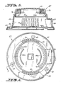
- FIG. 1 illustrates the upper portion of so-called bypass type vacuum cleaner 20 including vertically upright tank 21, circular in horizontal cross-section, having lid assembly 25 removably secured to its upper end by a plurality of pivoted latches 24.
- Inlet fitting 22 for the attachment of a vacuum hose is secured to tank 21 at a side opening near the top thereof.
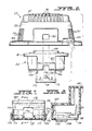
- the main elements of assembly 25 are electric motor 26, inverted cup-like motor cover 27, cap 23, blower housing 28, pancake type fan impeller 29, fan cover 31 and tank lid 32 having float cage 33 depending therefrom and formed integrally therewith.
- the upper end of motor 26 is disposed within cap 23 and the lower end of motor 26 is disposed within depression 34 in the upper surface of blower housing 28.
- Impeller 29 is secured to the lower end of motor shaft 35 and is disposed within chamber 36 formed between formations of housing 28 and cover 31.
- ball type float 37 is disposed within cage 33 and positioned below cover 31.
- motor 26 in addition to vertically positioned shaft 35, motor 26 includes wound rotor 38 mounted to shaft 35 and disposed within the central passage through laminated pole piece means 40.
- An upper bearing (not shown) for shaft 35 is secured to the web portion of inverted U-shaped metal bracket 42 and a lower bearing 43 (Fig. 2) for shaft 35 is disposed within annular extension 44 at the lower end of molded insulated lower housing 45.
- Screws (not shown) extend through outwardly turned feet of bracket 42 and through clearance apertures in pole piece 40, and are threadably received in apertures of lower housing 45 to sandwich pole means or field stack 40 in operative position between bracket 42 and lower housing 45.
- Cooling fan blade 47 is mounted to the upper end of motor shaft 35 and rotates between the spaced arms of bracket 42.
- Rotor 38 is electrically energized through a pair of carbon brushes 48 disposed within radially extending housings 49 formed integrally with housing 45.
- a coiled compression spring (not shown) disposed within brush housing 49 biases the radially inner end of each brush 48 against the commutator 51 mounted on shaft 35.
- the upper portion 53 of housing 45 is generally cylindrical and is connected to annular extension 44 by perforated conical section 54.
- Lower housing 45 is also provided with apertures that threadably receive screws 55 (Fig. 1) which secure lower housing 28 directly to motor 26.
- the upper end of field piece 40 extends into cap 23 which is disposed within cover 27. For a reason to be seen hereinafter, cap 23 is molded of plastic flame retardant material.
- motor cover 27 is an inverted cup-shaped member including sloping annular side wall 59 that extends downward from slightly convex horizontal top wall 61. Extending outwardly from the bottom of wall 59 is annular shoulder 60 having three clearance apertures 62 which receive individual screws 63 (Fig. 1) that secure motor housing 27 directly to lower housing 28.
- the slightly inwardly stepped upper portion of sidewall 59 is provided with diametrically opposed sets of motor cooling air inlet apertures 76, and the lower portion of sidewall 59 is provided with diametrically opposed sets of cooling air exhaust apertures 77.
- the sets of intake apertures 76 are offset from exhaust apertures 77 by approximately 90°.
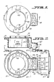
- motor cap 23 includes generally annular skirt 67 that extends downward from flat horizontal top wall 68 having short generally annular interrupted partition 69 extending upward therefrom. Skirt 67 and partition 69 are essentially coaxial.
- the periphery of top wall 68 is provided with downwardly extending lip 81 which, when cap 23 and cover 27 are assembled (Fig. 3), lies adjacent to the inner surface of annular lip 82 in the interior of motor cover 27.
- Diametrically opposite portions of wall 67 are flattened to conform with the sidewall of field stack 40, the upper portion of which extends into the area surrounded by wall 67.
- Notch 67a extending upwardly from the bottom of wall 67 provides clearance for horizontally projecting grounding terminal 83 of motor bracket 42.
- notch 67a Diametrically opposed to notch 67a is rectangular aperture 67b which receives a slight projection (not shown) that extends horizontally outward from the side of bracket 42 opposite terminal 83, there being a snap fit between this projection and aperture 67 so that there will not be accidental disengagement of motor cap 23 from motor 26.
- Junction box 167 formed integrally with motor cap 23, projects outwardly from sidewall 67 thereof.
- Box 167 is generally rectangular, having perforated top wall 168 and an open bottom that is normally closed by perforated cover 170 having elongated slots 171 at opposite ends thereof. Slots 171 receive retainer projections 172 that extend downward from opposite endwalls of junction box 167. The free end portions of projections 172 are provided with short clips 199 that project outwardly so as to be in blocking relationship with cover 170 when the latter is mounted to box 167. There is sufficient resiliency in projections 172 to permit inward deflection thereof for dismounting cover 170 from box 167.
- Exterior sidewall 174 of box 167 is provided with notch 176 that is partially closed by cover 170 to define rectangular aperture 177 through which horizontally slidable manual operating handle 88 of ON-OFF control switch 87 extends. Opposite edges of mounting plate 89 for switch 87 are captured within interior slots 181 (Fig. 13) of box 167. Strain relief 136 surrounding three conductor line cord 79 is received by formation 137 in shoulder 60 of motor housing 27.
- Grounding lead 84 of line cord 75 is connected directly to bracket terminal 83, line cord conductor 82 and motor lead 78 are connected to one another by wire nut 79, disposed within box 167, the other motor lead 168 is connected to one terminal of switch 87, and conductor 83 of line cord 75 is connected to the other terminal of switch 87.
- Motor conductors 78 and 168 extend into box 167 through clearance 183 (Fig. 8) which also provides a space for the entry of line cord conductor 83.
- Rectangular aperture 185 in motor cover 27 is in alignment with junction box aperture 177 so that ON-OFF control 88 is accessible from outside of cover 27.
- junction box 167 is disposed within cover recess 66 and internal lip 82 of cover 27 surrounds cap lip 81 in snug engagement therewith.
- motor cooling fan 47 rotates and draws air into housing 27 through inlet slots 76. This air moves along the upper surface of wall 68 and downward through aperture 189, then downward through motor 26 to cool the elements thereof. After performing its cooling function the air moved by rotation of fan 47 flows upward along the outside of field stack 40 and cap sidewall 67, leaving housing 27 through exhaust slots 77. A portion of this upwardly moving cooling air circulates through junction box 167 by means of the apertures in its top wall and bottom cover 170.
- blower housing 28 is a member molded of plastic material and includes two clearance apertures for screws 55 that mechanically secure housing 28 directly to lower motor cover 45.
- housing 28 is provided with depressed portion 131 having centrally located short upwardly extending sleeve 92 that is closely fitted around the outside of downward extension 44 of lower motor cover 45 to form a water-tight seal.
- Inclined upper edge surfaces of webs 93 engage the conical exterior surface 54 of blower motor housing 45 to fix the position of motor 26 at its lower end.
- Housing 28 is provided with exhaust port 94 which is laterally offset from depressed portion 131 and communicates with an expansion plenum that receives the main stream of air produced by rotation of impeller 29 after such air passes through vanes 96, formed integrally with blower housing 28 at the bottom thereof, and along the outer side surface of depressed portion 131. Vanes 96 are disposed in a circular array above and slightly outboard of the periphery of impeller 29.
- Fan cover 31 is in the form of a shallow dish 99 that provides chamber 36 wherein impeller 29 is disposed. Outwardly extending lip 101 at the upper end of dish 99 is provided with three clearance apertures 102 through which screws 103 (Fig. 1) extend to mechanically secure fan cover 31 directly to the bottom of blower housing 28. Air intake aperture 106 disposed at the center of dish 99 is covered by grillwork 107. Surrounding intake aperture 106 and extending downward from dish 99 is annular flange 108 which is of the diameter and length that will permit ball 37 to be floated into sealing engagement therewith. Ribs 109 extend radially outward from flange 108 to rigidify cover 31.
- Annular flange 133 extending upward from lid 32 closely surrounds lip 101 of fan cover 31 while downwardly extending annular flange 138 of lid 32 lies adjacent the inner side surface of tank 21. Seven screws 112 extend upward through clearance apertures in lid 32 and are threadably received in bores 114 of blower housing 28 to mechanically secure the latter to lid 32. Lip 101 is also sandwiched between lid 32 and portions of blower housing 28 so that cover 31 cannot be removed while lid 32 is secured to housing 28.
- a strap may be used to loosely hold cover 170 to box 167 so that the former will not be misplaced when box 167 is open.
- This strap may be formed as a separate element or may be molded integrally with one or both of the components 167, 170.
- Junction box cover 170 is also molded of plastic material that is fire resistant so that if the remaining portions of vacuum 20 are destroyed by fire, the electrical connections within junction box 167 will not be exposed.
Landscapes
- Engineering & Computer Science (AREA)
- Mechanical Engineering (AREA)
- Motor Or Generator Frames (AREA)
- Electric Suction Cleaners (AREA)
- Structures Of Non-Positive Displacement Pumps (AREA)
- Filters For Electric Vacuum Cleaners (AREA)
- Addition Polymer Or Copolymer, Post-Treatments, Or Chemical Modifications (AREA)
Applications Claiming Priority (2)
| Application Number | Priority Date | Filing Date | Title |
|---|---|---|---|
| US94057686A | 1986-12-12 | 1986-12-12 | |
| US940576 | 1986-12-12 |
Publications (2)
| Publication Number | Publication Date |
|---|---|
| EP0270935A2 true EP0270935A2 (de) | 1988-06-15 |
| EP0270935A3 EP0270935A3 (de) | 1988-10-05 |
Family
ID=25475080
Family Applications (1)
| Application Number | Title | Priority Date | Filing Date |
|---|---|---|---|
| EP87117458A Withdrawn EP0270935A3 (de) | 1986-12-12 | 1987-11-26 | Motorhaube und Gehäuse für Nass-/Trockensauger |
Country Status (7)
| Country | Link |
|---|---|
| EP (1) | EP0270935A3 (de) |
| JP (1) | JPS63171533A (de) |
| AU (1) | AU589822B2 (de) |
| CA (1) | CA1300829C (de) |
| DK (1) | DK650987A (de) |
| IE (1) | IE61187B1 (de) |
| NZ (1) | NZ222871A (de) |
Cited By (6)
| Publication number | Priority date | Publication date | Assignee | Title |
|---|---|---|---|---|
| WO2000025656A1 (de) * | 1998-10-31 | 2000-05-11 | Miele & Cie. Gmbh & Co. | Staubsaugergebläse |
| WO2000072740A1 (en) * | 1999-05-31 | 2000-12-07 | Türk Elektrik Endüstrisi A.Ş. | Wet and dry electrical vacuum cleaner motor with reduced balance problems arising from assembly |
| KR100456174B1 (ko) * | 2002-09-24 | 2004-11-09 | 삼성광주전자 주식회사 | 습건식 진공청소기 |
| WO2006053764A1 (de) * | 2004-11-19 | 2006-05-26 | Andreas Weinberg | Staubsauger |
| EP3115742A1 (de) | 2015-07-10 | 2017-01-11 | Hexagon Technology Center GmbH | 3d-messmaschine |
| US11670977B2 (en) | 2019-04-24 | 2023-06-06 | Black & Decker Inc. | Outer rotor brushless motor stator mount |
Families Citing this family (1)
| Publication number | Priority date | Publication date | Assignee | Title |
|---|---|---|---|---|
| JP5951314B2 (ja) * | 2012-03-27 | 2016-07-13 | 株式会社東芝 | 電気掃除機 |
Family Cites Families (5)
| Publication number | Priority date | Publication date | Assignee | Title |
|---|---|---|---|---|
| US3780397A (en) * | 1973-01-03 | 1973-12-25 | Singer Co | Wet/dry suction cleaner |
| US3815172A (en) * | 1973-01-03 | 1974-06-11 | Singer Co | Wet/dry suction cleaner |
| US4114231A (en) * | 1977-03-04 | 1978-09-19 | Nauta Jelle G | Motor ventilation system for wet/dry vacuum cleaner |
| US4330899A (en) * | 1980-04-18 | 1982-05-25 | Shop-Vac Corporation | Noise reducing blower motor housing means for vacuum cleaner, or the like |
| US4538971A (en) * | 1983-07-18 | 1985-09-03 | Shop-Vac Corporation | Assembly of tank lid and fan means of a wet/dry vacuum |
-
1987
- 1987-11-19 AU AU81384/87A patent/AU589822B2/en not_active Ceased
- 1987-11-26 EP EP87117458A patent/EP0270935A3/de not_active Withdrawn
- 1987-11-27 IE IE322787A patent/IE61187B1/en not_active IP Right Cessation
- 1987-12-10 NZ NZ22287187A patent/NZ222871A/xx unknown
- 1987-12-11 CA CA000554083A patent/CA1300829C/en not_active Expired - Fee Related
- 1987-12-11 DK DK650987A patent/DK650987A/da not_active Application Discontinuation
- 1987-12-12 JP JP31505787A patent/JPS63171533A/ja active Pending
Cited By (9)
| Publication number | Priority date | Publication date | Assignee | Title |
|---|---|---|---|---|
| WO2000025656A1 (de) * | 1998-10-31 | 2000-05-11 | Miele & Cie. Gmbh & Co. | Staubsaugergebläse |
| US7651325B1 (en) | 1998-10-31 | 2010-01-26 | Miele & Cie. Kg | Vacuum cleaner fan |
| WO2000072740A1 (en) * | 1999-05-31 | 2000-12-07 | Türk Elektrik Endüstrisi A.Ş. | Wet and dry electrical vacuum cleaner motor with reduced balance problems arising from assembly |
| KR100456174B1 (ko) * | 2002-09-24 | 2004-11-09 | 삼성광주전자 주식회사 | 습건식 진공청소기 |
| WO2006053764A1 (de) * | 2004-11-19 | 2006-05-26 | Andreas Weinberg | Staubsauger |
| EP3115742A1 (de) | 2015-07-10 | 2017-01-11 | Hexagon Technology Center GmbH | 3d-messmaschine |
| US10254404B2 (en) | 2015-07-10 | 2019-04-09 | Hexagon Technology Center Gmbh | 3D measuring machine |
| US11670977B2 (en) | 2019-04-24 | 2023-06-06 | Black & Decker Inc. | Outer rotor brushless motor stator mount |
| US11973374B2 (en) | 2019-04-24 | 2024-04-30 | Black & Decker Inc. | Outer rotor brushless motor having an axial fan |
Also Published As
| Publication number | Publication date |
|---|---|
| CA1300829C (en) | 1992-05-19 |
| NZ222871A (en) | 1989-07-27 |
| IE61187B1 (en) | 1994-10-19 |
| JPS63171533A (ja) | 1988-07-15 |
| EP0270935A3 (de) | 1988-10-05 |
| DK650987D0 (da) | 1987-12-11 |
| IE873227L (en) | 1988-06-12 |
| DK650987A (da) | 1988-06-13 |
| AU589822B2 (en) | 1989-10-19 |
| AU8138487A (en) | 1988-06-16 |
Similar Documents
| Publication | Publication Date | Title |
|---|---|---|
| EP0134963B1 (de) | Behälterdeckel- und Ventilatormontage eines nassen/trockenen Saugers | |
| EP0493654B1 (de) | Tragbares elektrisches Gebläse | |
| US4880364A (en) | Portable electric blower | |
| US4836753A (en) | Portable electric blower | |
| KR100238512B1 (ko) | 천정카셋트형 공기조화기 | |
| CA1203354A (en) | Noise reducing means for vacuum cleaner | |
| US4213224A (en) | By-pass type portable vacuum cleaner | |
| US4655694A (en) | Housing assembly for motor/fan means of a wet/dry vacuum cleaner | |
| US4693734A (en) | Vacuum cleaner construction | |
| US4547927A (en) | Compact vacuum cleaner | |
| EP0270935A2 (de) | Motorhaube und Gehäuse für Nass-/Trockensauger | |
| US2027158A (en) | Vacuum cleaner | |
| US2136268A (en) | Vacuum cleaner | |
| US6729859B2 (en) | Airflow generating device air intake | |
| CN114668333B (zh) | 一种吸尘器 | |
| JPH09243109A (ja) | 天井設置型空気調和装置 | |
| CA1331871C (en) | Portable electric blower | |
| JPH06108994A (ja) | 電動送風機 | |
| HK1006942B (en) | Portable electric blower | |
| JPH0628984Y2 (ja) | 電動芝刈機の電動機冷却構造 | |
| JPS6034023B2 (ja) | 縦形ル−ムエアコンデイシヨナ | |
| JPH06108995A (ja) | 電動送風機 | |
| CA1264212A (en) | Compact vacuum cleaner | |
| JPH0415999Y2 (de) | ||
| JPS6222375B2 (de) |
Legal Events
| Date | Code | Title | Description |
|---|---|---|---|
| PUAI | Public reference made under article 153(3) epc to a published international application that has entered the european phase |
Free format text: ORIGINAL CODE: 0009012 |
|
| AK | Designated contracting states |
Kind code of ref document: A2 Designated state(s): AT BE CH DE ES FR GB GR IT LI LU NL SE |
|
| PUAL | Search report despatched |
Free format text: ORIGINAL CODE: 0009013 |
|
| AK | Designated contracting states |
Kind code of ref document: A3 Designated state(s): AT BE CH DE ES FR GB GR IT LI LU NL SE |
|
| STAA | Information on the status of an ep patent application or granted ep patent |
Free format text: STATUS: THE APPLICATION IS DEEMED TO BE WITHDRAWN |
|
| 18D | Application deemed to be withdrawn |
Effective date: 19890406 |
|
| RIN1 | Information on inventor provided before grant (corrected) |
Inventor name: BERFIELD, ROBERT C. Inventor name: MELAND, RONALD |