EP0270901A2 - Centrifuge de filage - Google Patents
Centrifuge de filage Download PDFInfo
- Publication number
- EP0270901A2 EP0270901A2 EP87117262A EP87117262A EP0270901A2 EP 0270901 A2 EP0270901 A2 EP 0270901A2 EP 87117262 A EP87117262 A EP 87117262A EP 87117262 A EP87117262 A EP 87117262A EP 0270901 A2 EP0270901 A2 EP 0270901A2
- Authority
- EP
- European Patent Office
- Prior art keywords
- spinning
- extruder
- spinning centrifuge
- centrifuge
- pump
- Prior art date
- Legal status (The legal status is an assumption and is not a legal conclusion. Google has not performed a legal analysis and makes no representation as to the accuracy of the status listed.)
- Granted
Links
Images

Classifications
-
- D—TEXTILES; PAPER
- D01—NATURAL OR MAN-MADE THREADS OR FIBRES; SPINNING
- D01D—MECHANICAL METHODS OR APPARATUS IN THE MANUFACTURE OF ARTIFICIAL FILAMENTS, THREADS, FIBRES, BRISTLES OR RIBBONS
- D01D5/00—Formation of filaments, threads, or the like
- D01D5/18—Formation of filaments, threads, or the like by means of rotating spinnerets
Definitions
- the invention relates to a spinning centrifuge according to the preamble of claim 1.
- Such a spinning centrifuge is known from European patent application 168 817.
- the spinning mass is pumped as a spinnable liquid through an extruder, which is arranged outside the spinning pump, into the central inlet of the spinning pump.
- the purpose of this measure is to increase the spinning pressure beyond what can be achieved by centrifugal acceleration.
- the disadvantage of the known spinning centrifuge is that dynamic seals between the feed line and the rotating inlet channel of the spinning centrifuge are required, which in addition to the dynamic loads must also withstand considerable thermal loads and are therefore not permanently sealed. Sealing with a gas supply is not appropriate, since this would require regulation of the liquid level in the sealing space occupied by the gas supply.
- the invention creates a spinning centrifuge in which the spinning liquid is supplied under pressure and which does not require a seal.
- the invention results from the characterizing part of claim 1.
- the advantage of the spinning centrifuge according to the invention is in particular that the inlet pressure of the spinning centrifuge can be chosen to be very high due to the lack of a seal.
- An extruder is used in particular as a pump according to this invention.
- the advantage of the extruder is that it consists of the coaxial pairing of screw and cylinder and can therefore be integrated into the central inlet of the spinning centrifuge in a simple construction.
- the advantage of the extruder is that it does not require any pressure-loaded seals on the inlet side.
- the casing rotates according to the invention in the pump and in particular in the extruder, it is further suggested as preferred to convey the spinning mass either in liquid form or in a still solid form of a powder or granulate into the stationary screw, the screw then having an axial filling channel with radial Has outlet channels that open into the worm gear.
- the extruder is designed as a liquid pump or as a conveying device for powder or granules.
- the dope is fed in a metered amount.
- the minimum amount must at least correspond to the amount that would be spun if the liquid spin mass in the spinning centrifuge was only affected by the spin pressure caused by centrifugal acceleration.
- the spinning mass can be supplied as a powder or granulate.
- the extruder is advantageously equipped so that the spinning mass is melted in it. It should be in the extruder internal heat generated due to the high speed of the cylinder relative to the screw is generally sufficient for melting. If this is not the case, contactless heating, for example by radiation or induction, is proposed by the invention.
- the spinning mass is supplied in liquid form, this can be done by means of a metering pump after the spinning mass e.g. has been melted in an extruder.
- the melting extruder immediately before the extruder assigned to the spinning centrifuge.
- degassing takes place in the inlet of the extruder assigned to the spinning centrifuge.
- a degassing hole can be provided in the stationary screw. If the screw has a central inlet channel through which melt is fed, the degassing and vacuum connection is parallel to the central inlet channel and opens into the region of the screw channel in which the radial outlet channels of the central channel also open.
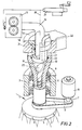
- Fig. 1 the section through a spinning centrifuge 1 is shown.
- the centrifuge consists of the centrifuge wheel 2 and the central centrifuge inlet 3 firmly connected to it.
- the centrifuge wheel 2 has a disk-shaped radial space 4 or more radial channels.
- the radial space 4 starts from the central inlet 3 and opens into spinning bores 5 on the circumference of the centrifuge wheel 2.
- the central inlet 3 is designed as an extruder jacket.
- the extruder jacket is rotatably supported in bearings 6.
- the extruder jacket 3 is driven by the drive wheel 7 and drive belt 9 of the drive motor 8 at high speed, e.g. 500 rpm. driven.
- the extruder jacket 3 is heated on a section by heating jacket 15.
- the heating jacket 15 is populated with a large number of electric heating elements or heating tubes.
- the heat transfer is preferably carried out without contact and by radiation, the heating jacket 15 being arranged in a stationary manner and forming a narrow gap
- the extruder jacket 3 At its free end, the extruder jacket 3 is conical in the inlet area, so that it forms a filling end 10.
- the taper is only weak, since otherwise there is a risk that the filled granules will be thrown outwards by the centrifugal force.
- the extruder jacket is provided with axial grooves on the inlet side following the filler neck 10.
- the extruder screw 11 is mounted in the extruder jacket 3 in the holder 12 in a stationary and stationary manner. In this exemplary embodiment, it extends almost to the level of the radial space 4. Otherwise, it is a conventional extruder design, the design of which depends on the material to be spun (spinning mass) and the other operating conditions, in particular the speed of the centrifuge wheel. If the speed of the centrifuge wheel 2 too unto casual shear rates and shear forces in the material to be spun, the screw can be rotatably supported and driven by an additional drive motor in the direction of rotation of the extruder jacket 3, so that the relative speed between the screw 11 and extruder jacket 3 is reduced.
- the spinning mass is fed in the form of granules through metering device 13, which consists of a hopper and a conveyor belt. It is ensured that the quantity supplied per unit of time does not exceed or exceed certain limit values which depend on the speed of the centrifuge wheel 2. falls below. Exceeding the limit value is in itself harmless and only leads to overflow of the filler neck 10. The lower limit value must not be undercut.
- the lower limit is the amount of the spinnable mass per unit of time (spinning amount) that would be spun out under the given operating conditions (in particular temperature, viscosity) at a pressure which is only generated by centrifugal acceleration at the given speed. If the amount of spinning mass added fell below this limit, the spinning centrifuge would run empty. Otherwise, there is a self-regulation between the two limit values, since a balance is established between the quantity supplied, the pressure generated by the extruder and the centrifugal acceleration on the spinning mass and the quantity spun out.
- the extruder 2 also consists of the centrifuge wheel 2 and the central inlet 3, which is designed as an extruder jacket.
- the extruder jacket 3 is rotatably supported in bearings 6 and is driven in rotation by drive belt 9 and drive wheel 7 and drive motor 9 ben.
- the spinnerets are labeled 5.
- the emerging threads can be seen.
- radial channels are located in the interior of the centrifuge wheel, which connect the central inlet 3 to the spinning bores 5.
- the extruder screw 11 in the exemplary embodiment according to FIG. 2 consists of the lower cylindrical part 11, which extends approximately into the centrifuge wheel 2, as well as a filling area 16 and a holder part 17.
- a precisely metered amount is fed into the filler channel 18 and the worm gear-like recess 20 to the extruder.
- the metering pump 13 is fed through the melt extruder 24.
- the dope is fed to the melting extruder 24 as a powder or granulate in a metered amount.
- the spinning mass melted by melting extruder 24 can also be fed directly into the filler pipe 19 of the extruder screw 11 and the spinning centrifuge 1.
- the holding part 17 of the extruder screw 11 has a vacuum connection 22, which serves as a degassing channel.
- the degassing duct is parallel to the filler duct 18 and opens into the worm gear-like recess 20, in which the introduced liquid spinning mass enters the worm thread radially outward from the central filler duct 18.
- a vacuum pump can be connected to the degassing duct 22. This favors the degassing.
- a seal is designated, through which the filler tube 19 is sealed in the filler channel 18 of the screw. It should be noted that this seal only has to withstand the very low melt pressures in the filling area of the extruder. The same applies to the seal 23, which seals the holding part 17 of the screw from the filler neck 10 of the extruder casing 3. Between the seals 21 and 23 is the area of the melt path in which the melt is exposed to the vacuum.
- an extruder located in the central inlet of the spinning centrifuge has the advantage that such an extruder does not require a seal that is under high pressure.
- the extruder can therefore generate pressures which correspond to the pressures customary in spinning.
- the pressure generated by the centrifugal acceleration is added to this pressure. It is therefore possible to spin even highly viscous melts with fine titers without increasing the thread pulling speed from the nozzles to an unacceptable degree.
- spinnerets with very small cross sections can be used.
- the speed of the spinning centrifuge can be set and optimized independently of the pressure required for spinning.
Landscapes
- Engineering & Computer Science (AREA)
- Mechanical Engineering (AREA)
- Textile Engineering (AREA)
- Spinning Methods And Devices For Manufacturing Artificial Fibers (AREA)
Applications Claiming Priority (2)
| Application Number | Priority Date | Filing Date | Title |
|---|---|---|---|
| DE3640962 | 1986-11-29 | ||
| DE19863640962 DE3640962A1 (de) | 1986-11-29 | 1986-11-29 | Spinnzentrifuge |
Publications (3)
| Publication Number | Publication Date |
|---|---|
| EP0270901A2 true EP0270901A2 (fr) | 1988-06-15 |
| EP0270901A3 EP0270901A3 (en) | 1988-08-31 |
| EP0270901B1 EP0270901B1 (fr) | 1990-12-27 |
Family
ID=6315179
Family Applications (1)
| Application Number | Title | Priority Date | Filing Date |
|---|---|---|---|
| EP87117262A Expired - Lifetime EP0270901B1 (fr) | 1986-11-29 | 1987-11-24 | Centrifuge de filage |
Country Status (5)
| Country | Link |
|---|---|
| US (1) | US5075063A (fr) |
| EP (1) | EP0270901B1 (fr) |
| JP (1) | JPS63145405A (fr) |
| DE (2) | DE3640962A1 (fr) |
| ES (1) | ES2020996B3 (fr) |
Families Citing this family (7)
| Publication number | Priority date | Publication date | Assignee | Title |
|---|---|---|---|---|
| US9731466B2 (en) * | 2012-08-06 | 2017-08-15 | Clarcor Inc. | Systems and methods of supplying materials to a rotating fiber producing device |
| JP5656297B2 (ja) * | 2012-12-25 | 2015-01-21 | 株式会社日本製鋼所 | 遠心紡糸装置及び遠心紡糸方法 |
| CN105473296A (zh) * | 2013-07-05 | 2016-04-06 | 北面服饰公司 | 纤维和长丝的力纺丝 |
| KR101884696B1 (ko) * | 2016-01-15 | 2018-08-03 | 나필찬 | 나노섬유 방사 장치 |
| KR101823995B1 (ko) | 2016-01-18 | 2018-02-01 | 경북대학교 산학협력단 | 나노섬유 방사장치 |
| CN110257934A (zh) * | 2019-06-26 | 2019-09-20 | 广东工业大学 | 一种熔融离心纺丝生产设备 |
| CN114086318B (zh) * | 2020-08-25 | 2023-02-10 | 华中科技大学 | 一种高速旋风协同的超重力熔喷纺丝装置及其使用方法 |
Family Cites Families (15)
| Publication number | Priority date | Publication date | Assignee | Title |
|---|---|---|---|---|
| NL119272B (fr) * | 1943-05-14 | 1900-01-01 | ||
| DE889566C (de) * | 1950-09-27 | 1953-09-10 | Unda Anstalt | Vorrichtung zur Auffaserung und Homogenisierung, insbesondere von tierischem Hautmaterial, zur Herstellung kuenstlicher Hautgebilde mittels Formduesen |
| US2715753A (en) * | 1954-05-10 | 1955-08-23 | Ind Rayon Corp | Multiple end spinning and twisting apparatus |
| US3488416A (en) * | 1967-09-27 | 1970-01-06 | Owens Illinois Inc | Elastic melt extruder and method of operation |
| FR1588880A (fr) * | 1968-09-06 | 1970-03-16 | ||
| DE1927067A1 (de) * | 1969-05-28 | 1970-12-10 | Barmag Barmer Maschf | Schneckenpresse fuer thermoplastische Werkstoffe |
| US3748074A (en) * | 1969-10-17 | 1973-07-24 | H Nitta | Apparatus for plasticizing thermoplastic synthetic resin |
| US3596312A (en) * | 1970-02-10 | 1971-08-03 | Koei Ohmatsu | Apparatus for producing synthetic resin fibers utilizing centrifugal force |
| DE2013997A1 (de) * | 1970-03-24 | 1971-10-21 | Farbenfabriken Bayer Ag, 5090 Leverkusen | Verfahren zur Herstellung von Monofilen aus einem Polyamid-Polyestergemisch durch Schmelzspinnen |
| US3737506A (en) * | 1970-04-03 | 1973-06-05 | Viscose Suisse Soc D | Process and apparatus for continuous extrusion of highly-viscous melts |
| JPS4825003B1 (fr) * | 1970-12-29 | 1973-07-25 | ||
| US3800985A (en) * | 1971-04-15 | 1974-04-02 | Kenics Corp | System and method for distributing highly viscous molten material |
| JPS59196208A (ja) * | 1983-04-22 | 1984-11-07 | Japan Steel Works Ltd:The | 溶融樹脂脱気装置 |
| US4790736A (en) * | 1984-07-20 | 1988-12-13 | John E. Benoit | Apparatus for centrifugal fiber spinning with pressure extrusion |
| JPH084703A (ja) * | 1994-06-21 | 1996-01-09 | Shimadzu Corp | 液圧サーボ装置 |
-
1986
- 1986-11-29 DE DE19863640962 patent/DE3640962A1/de not_active Withdrawn
-
1987
- 1987-11-24 DE DE8787117262T patent/DE3767141D1/de not_active Expired - Fee Related
- 1987-11-24 EP EP87117262A patent/EP0270901B1/fr not_active Expired - Lifetime
- 1987-11-24 ES ES87117262T patent/ES2020996B3/es not_active Expired - Lifetime
- 1987-11-25 US US07/125,132 patent/US5075063A/en not_active Expired - Fee Related
- 1987-11-27 JP JP62297903A patent/JPS63145405A/ja active Pending
Also Published As
| Publication number | Publication date |
|---|---|
| EP0270901B1 (fr) | 1990-12-27 |
| US5075063A (en) | 1991-12-24 |
| JPS63145405A (ja) | 1988-06-17 |
| DE3767141D1 (de) | 1991-02-07 |
| ES2020996B3 (es) | 1991-10-16 |
| EP0270901A3 (en) | 1988-08-31 |
| DE3640962A1 (de) | 1988-06-09 |
Similar Documents
| Publication | Publication Date | Title |
|---|---|---|
| EP0597271B1 (fr) | Procédé pour le traitement de fonte thermoplastique avec une pompe à engrenages | |
| US3664795A (en) | Screw extruders with dual section ejection zone | |
| GB1590506A (en) | Process for the concentration of solutions with simultaneous setting | |
| WO2007090849A1 (fr) | Essoreuse centrifuge A vis et enveloppe complete et SON procede D'utilisation | |
| EP0270901B1 (fr) | Centrifuge de filage | |
| DE1941673A1 (de) | Zahnradpumpe mit keilfoermig verjuengten Einzugskammern | |
| DE2924317C2 (de) | Zweistufige Strangpreßvorrichtung für thermoplastische Formmassen, insbesondere für pulverförmige Kunststoffe | |
| DE10342822B4 (de) | Extruder zum Herstellen von syntaktischem Kunststoff | |
| EP3999296B1 (fr) | Extrudeuse conçue pour préparer des polymères fusibles de manière à accroître leur viscosité | |
| EP0100945B1 (fr) | Partie de trémie d'une extrudeuse à vis unique | |
| EP0426790B1 (fr) | Dispositif pour le formage de matieres synthetiques thermoplastiques | |
| DE2360735C3 (de) | Extruder für Kunststoff | |
| DE69736361T2 (de) | Bildung einer Lösung aus Fluiden mit niedriger Mischbarkeit und grossem Unterschied in der Viskosität | |
| DE3915603C1 (fr) | ||
| EP3995278A1 (fr) | Procédé et dispositif de traitement de polycondensats | |
| DE2212389A1 (de) | Verfahren und Vorrichtung zur Foerderung von partikelfoermigem Material aus einer Speisezone in eine Ablieferungszone,insbesondere fuer das Schmelzspinnen,sowie Schmelzererzeugungseinheit und Schmelzspinnmaschine hierfuer | |
| DE2654774B2 (de) | Schneckenmaschine zur Homogenisierung von aufgeschmolzenen Polymeren | |
| EP3175967A1 (fr) | Procédé de préparation d'une fusion de styrène-acrylonitrile | |
| DE2910041C2 (de) | Schneckenpresse zur Verarbeitung von polymeren Materialien | |
| US3131430A (en) | Extrusion worm for the melting of organic thermoplastics | |
| US3474773A (en) | Polymer melt screw pump for fiber spinning | |
| DE2406569A1 (de) | Verfahren und vorrichtung zum strangpressen von thermoplastischen werkstoffen | |
| DE2332803C3 (de) | Vorrichtung zum Herstellen von Folien und Platten aus thermoplastischen Kunststoffen | |
| DE3142948C2 (de) | Einwellige Schneckenpresse | |
| DE2630173A1 (de) | Verfahren und vorrichtung zur verkuerzung der molekuelketten bei polymeren |
Legal Events
| Date | Code | Title | Description |
|---|---|---|---|
| PUAI | Public reference made under article 153(3) epc to a published international application that has entered the european phase |
Free format text: ORIGINAL CODE: 0009012 |
|
| AK | Designated contracting states |
Kind code of ref document: A2 Designated state(s): BE CH DE ES FR GB IT LI LU NL |
|
| PUAL | Search report despatched |
Free format text: ORIGINAL CODE: 0009013 |
|
| AK | Designated contracting states |
Kind code of ref document: A3 Designated state(s): BE CH DE ES FR GB IT LI LU NL |
|
| 17P | Request for examination filed |
Effective date: 19880722 |
|
| 17Q | First examination report despatched |
Effective date: 19900504 |
|
| ITF | It: translation for a ep patent filed | ||
| GRAA | (expected) grant |
Free format text: ORIGINAL CODE: 0009210 |
|
| AK | Designated contracting states |
Kind code of ref document: B1 Designated state(s): BE CH DE ES FR GB IT LI LU NL |
|
| ET | Fr: translation filed | ||
| REF | Corresponds to: |
Ref document number: 3767141 Country of ref document: DE Date of ref document: 19910207 |
|
| GBT | Gb: translation of ep patent filed (gb section 77(6)(a)/1977) | ||
| PLBE | No opposition filed within time limit |
Free format text: ORIGINAL CODE: 0009261 |
|
| STAA | Information on the status of an ep patent application or granted ep patent |
Free format text: STATUS: NO OPPOSITION FILED WITHIN TIME LIMIT |
|
| ITTA | It: last paid annual fee | ||
| 26N | No opposition filed | ||
| PGFP | Annual fee paid to national office [announced via postgrant information from national office to epo] |
Ref country code: ES Payment date: 19921119 Year of fee payment: 6 |
|
| PGFP | Annual fee paid to national office [announced via postgrant information from national office to epo] |
Ref country code: LU Payment date: 19931101 Year of fee payment: 7 |
|
| PGFP | Annual fee paid to national office [announced via postgrant information from national office to epo] |
Ref country code: GB Payment date: 19931116 Year of fee payment: 7 |
|
| PGFP | Annual fee paid to national office [announced via postgrant information from national office to epo] |
Ref country code: FR Payment date: 19931122 Year of fee payment: 7 |
|
| PG25 | Lapsed in a contracting state [announced via postgrant information from national office to epo] |
Ref country code: ES Free format text: LAPSE BECAUSE OF EXPIRATION OF PROTECTION Effective date: 19931125 |
|
| PGFP | Annual fee paid to national office [announced via postgrant information from national office to epo] |
Ref country code: CH Payment date: 19931126 Year of fee payment: 7 |
|
| PGFP | Annual fee paid to national office [announced via postgrant information from national office to epo] |
Ref country code: NL Payment date: 19931130 Year of fee payment: 7 |
|
| EPTA | Lu: last paid annual fee | ||
| PGFP | Annual fee paid to national office [announced via postgrant information from national office to epo] |
Ref country code: BE Payment date: 19940106 Year of fee payment: 7 |
|
| PG25 | Lapsed in a contracting state [announced via postgrant information from national office to epo] |
Ref country code: LU Free format text: LAPSE BECAUSE OF NON-PAYMENT OF DUE FEES Effective date: 19941124 Ref country code: GB Effective date: 19941124 |
|
| PG25 | Lapsed in a contracting state [announced via postgrant information from national office to epo] |
Ref country code: LI Effective date: 19941130 Ref country code: CH Effective date: 19941130 Ref country code: BE Effective date: 19941130 |
|
| BERE | Be: lapsed |
Owner name: BARMAG A.G. Effective date: 19941130 |
|
| PG25 | Lapsed in a contracting state [announced via postgrant information from national office to epo] |
Ref country code: NL Effective date: 19950601 |
|
| NLV4 | Nl: lapsed or anulled due to non-payment of the annual fee | ||
| GBPC | Gb: european patent ceased through non-payment of renewal fee |
Effective date: 19941124 |
|
| PG25 | Lapsed in a contracting state [announced via postgrant information from national office to epo] |
Ref country code: FR Effective date: 19950731 |
|
| REG | Reference to a national code |
Ref country code: CH Ref legal event code: PL |
|
| REG | Reference to a national code |
Ref country code: FR Ref legal event code: ST |
|
| PGFP | Annual fee paid to national office [announced via postgrant information from national office to epo] |
Ref country code: DE Payment date: 19951128 Year of fee payment: 9 |
|
| PG25 | Lapsed in a contracting state [announced via postgrant information from national office to epo] |
Ref country code: DE Effective date: 19970801 |
|
| REG | Reference to a national code |
Ref country code: ES Ref legal event code: FD2A Effective date: 20010301 |
|
| PG25 | Lapsed in a contracting state [announced via postgrant information from national office to epo] |
Ref country code: IT Free format text: LAPSE BECAUSE OF NON-PAYMENT OF DUE FEES Effective date: 20051124 |