EP0268378A2 - Akustisches Messinstrument zum Messen von Strom/Kraft/Widerstand - Google Patents
Akustisches Messinstrument zum Messen von Strom/Kraft/Widerstand Download PDFInfo
- Publication number
- EP0268378A2 EP0268378A2 EP87309207A EP87309207A EP0268378A2 EP 0268378 A2 EP0268378 A2 EP 0268378A2 EP 87309207 A EP87309207 A EP 87309207A EP 87309207 A EP87309207 A EP 87309207A EP 0268378 A2 EP0268378 A2 EP 0268378A2
- Authority
- EP
- European Patent Office
- Prior art keywords
- phonic
- signal
- digital
- bcd
- sent
- Prior art date
- Legal status (The legal status is an assumption and is not a legal conclusion. Google has not performed a legal analysis and makes no representation as to the accuracy of the status listed.)
- Withdrawn
Links
Images




Classifications
-
- G—PHYSICS
- G01—MEASURING; TESTING
- G01D—MEASURING NOT SPECIALLY ADAPTED FOR A SPECIFIC VARIABLE; ARRANGEMENTS FOR MEASURING TWO OR MORE VARIABLES NOT COVERED IN A SINGLE OTHER SUBCLASS; TARIFF METERING APPARATUS; MEASURING OR TESTING NOT OTHERWISE PROVIDED FOR
- G01D7/00—Indicating measured values
- G01D7/12—Audible indication of meter readings, e.g. for the blind
-
- G—PHYSICS
- G01—MEASURING; TESTING
- G01R—MEASURING ELECTRIC VARIABLES; MEASURING MAGNETIC VARIABLES
- G01R15/00—Details of measuring arrangements of the types provided for in groups G01R17/00 - G01R29/00, G01R33/00 - G01R33/26 or G01R35/00
- G01R15/12—Circuits for multi-testers, i.e. multimeters, e.g. for measuring voltage, current, or impedance at will
- G01R15/125—Circuits for multi-testers, i.e. multimeters, e.g. for measuring voltage, current, or impedance at will for digital multimeters
Definitions
- the invention relates to a kind of phonic meter for measuring current/force/resistance.
- the present invention offers a novelty meter whose reading can be identified not only by the display, but also by the phone of the phone processor.
- a preferred embodiment in accordance with ideas of this invention is described as follows:
- A/D converter analog-to-digital converter
- the preferred embodiment of phonic meter for electricity under present invention can utter the measured values as well as show them on the display.
- the present invention offers a novelty meter to meet above requirements.
- the present invention is featured of multimeter reading, not only by traditional display, but also by the phone of phone processor. Therefore, the maintenance engineers can identify the reading clearly.
- the present invention is a breakthrough in consideration of its ideas, function, and operation; and it does offer an innovatory, convenient and practical meter.
- the preferred embodiment of the phone meter incorporates both measurement reading means by phone and by digital display.
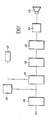
- An analog measurement signal from the meter is sent, via an attenuator 40, to an A/D converter 41 which is followed by a decoder 42.
- the decoded converted digital signal is passed to a phone processor 43 which generates a corresponding digital phone signal which, after amplification by an amplifier 44, will drive a speaker 45.
- the analog measurement signal can also drive an analog display 46 directly to show the corresponding analog reading and/or the BCD digital signal converted by the converter 41 can drive a digital display 47 to show the corresponding digital reading.
- the analog signal measured by the meter will be converted via an A/D converter into a digital signal which has two kinds of outputs: one is a BCD signal represented by B1, B2, B4 and B8 while the other is a digital scan signal represented by D5 - D1.
- the BCD signal is sent not only to a decoder 2 to drive a display 10, so as to show the corresponding digital reading, but also to a phone processor 5 via a register 4 to process the phonic digital signal output which will be sent to a filter amplify circuit 9 to generate a corresponding phonic reading.
- the digital scan signal is sent to a driver 3, to drive said display 10, and also controls the BCD data storage of said register 4.
- the data input of said register 4 is controlled by a counter 8, and the start or the end of the phonic reading is controlled by the output of an AND GATE 7.
- the timing pulse generated by a timer 6 and the pin 25 of said A/D converter 1 are two inputs of said AND GATE 7.
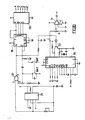
- the circuit diagram designed according to the block diagram in Fig. 2 is illustrated in Fig. 3A/3B as: the analog signal measured by the probe of said meter will be converted via a 4-1/2 digit A/D converter 11 into digital signal which includes a BCD signal (represented by B1, B2, B4, and B8) and a digital scan signal (represented by D5 - D1).
- Said digital scan signal has two functions: one is to control the data storage of the registers 14-18, and the other is to control the showing of the display 25.
- Said BCD signal represents the measured digital data and will be sent to said register 14-18 as well as to a BCD-to-7-segment decoder 12 to drive said display 25 so as to show the measurement readings.
- a timer 26 an unsteady multivibrator, will generate a square wave of appropriate frequency to serve as the timing pulse which will then be sent through AND GATE 27 whose output wave form will be determined by the output of pin 25 (RUN/HOLD) of said A/D converter 11.
- a switch SW1/SW2 of double poles and single throw is installed to control the start or the end of the output of phonic signal, and also the output status of a counter 28.
- the output of said AND GATE 27 is then be sent to pin 14 of a decimal counter 28 whose pin 12 has output connected with the input of pin 1 to perform BCD counting.
- Said BCD decimal counter 28 will then be connected with a ABCD-to-decimal decoder 29 whose output pins (pin 2 - pin 7) will respectively control the switch circuits 19-24. If the inputs of said switch circuits 19-24 are high, said switch circuits 19-24 are "ON”. On the contrary, if the inputs of said switch circuits 19-24 are low, said switch circuits 19-24 are "OFF". Besides, when said switch circuits 19-24 are "ON", the BCD data of the registers 14-18 can be sent to the phone processor 30. Among above six switch circuit 19-24, switch circuit 24 is to control the decimal point.
- the output pins A, B, C, D, E, F, of said decoder 29 respectively control said switch circuits 19-24, so as to show the measured reading valid up to one digit after the decimal point.
- the output pulse of said AND GATE 27 will be sent via a transistor 32 to said phone processor 30 which will then generate the corresponding phonic digital signal to be sent to a RC filter circuit, so as to convert the digital phone signal into analog phone signal which will then be amplified by an amplifier 31 to drive a speaker to send out corresponding measurement reading phone.
- the measured analog value will be converted via an A/D converter into digital signal to control the storage of the register. While the BCD signal of said digital signal will be sent first to the register controlled by the decimal counter, then to the phone processor to produce corresponding phone.
- the embodiments of the present invention can be: a simplified phonic meter; or based on designs mentioned above, a phonic meter with digital display by sending BCD signal to a decoder to generate the output signal to drive a digital display to show the corresponding measured value; or a phonic meter with analog display; or a phonic meter with other appropriate display means.
- Fig. 4A/4B is another preferred embodiment of this invention to illustrate as follows:
- Block A When the multimeter is selected for the function "V" or "K ", Block A will be activated.
- the main function of Block A is to maintain the output voltage within the 200 full scale, no matter where the selected range switch is set.
- Block C is a AC-to-DC RMS (root-mean-square) converter whose main function is to convert effective voltage values of AC into related voltage values of DC.
- Block D is the selection circuit of "K " function.
- Block E The main function of Block E is to generate the signal shown in Fig. 5b.
- Block F is the major function portion of this invention to insert the decimal point.
- a tri-state buffer serves as a range switch.
- the selection switch When the selection switch is set at different position, the signal sequence from said Block E will be selected to the buffers to put the position of decimal point into the correct position for phone reading. While said signal will be also sent to the decimal point selector of said LCD display.
- the measured digital signal will be stored in the ROM, then the corresponding data will be generated from said measured value as shown in the table below, so as to read different range by phone which will be pre-recorded before released.
- Block I is the phone process unit to select correct phone for data from the ROM, and said phones will be amplified first, then released by a speaker.
- the present invention offers a meter able to show the measurement reading by phone.
- the analog measurement signal will be converted via an A/D converter into digital signal which will be sent to a register and then to phone processor to produce phone.
- said digital signal can also be sent to a decoder to use the output signal to drive a display, so as to display the measurement reading.
- the embodiment of the present invention can be: a simplified phonic meter, a phonic multimeter, a phonic meter with analog display, a phonic meter with digital display, or a phonic meter with other types of display means. Therefore, the present invention offers an novelty meter of less reading-error and more convenience superior to the traditional meters.
Landscapes
- Physics & Mathematics (AREA)
- General Physics & Mathematics (AREA)
- Measuring Instrument Details And Bridges, And Automatic Balancing Devices (AREA)
- Arrangements For Transmission Of Measured Signals (AREA)
- Measurement Of Resistance Or Impedance (AREA)
Applications Claiming Priority (2)
| Application Number | Priority Date | Filing Date | Title |
|---|---|---|---|
| US92097386A | 1986-10-20 | 1986-10-20 | |
| US920973 | 1997-08-29 |
Publications (2)
| Publication Number | Publication Date |
|---|---|
| EP0268378A2 true EP0268378A2 (de) | 1988-05-25 |
| EP0268378A3 EP0268378A3 (de) | 1989-05-10 |
Family
ID=25444720
Family Applications (1)
| Application Number | Title | Priority Date | Filing Date |
|---|---|---|---|
| EP87309207A Withdrawn EP0268378A3 (de) | 1986-10-20 | 1987-10-19 | Akustisches Messinstrument zum Messen von Strom/Kraft/Widerstand |
Country Status (9)
| Country | Link |
|---|---|
| EP (1) | EP0268378A3 (de) |
| KR (1) | KR880005443A (de) |
| AU (1) | AU7944487A (de) |
| BR (1) | BR8705835A (de) |
| FI (1) | FI874536A7 (de) |
| IL (1) | IL84225A0 (de) |
| MX (1) | MX160173A (de) |
| PH (1) | PH23098A (de) |
| ZA (1) | ZA877631B (de) |
Cited By (3)
| Publication number | Priority date | Publication date | Assignee | Title |
|---|---|---|---|---|
| FR2641374A1 (fr) * | 1988-09-28 | 1990-07-06 | Cistac Andre | Appareil de mesure vocal |
| GB2248941A (en) * | 1990-10-17 | 1992-04-22 | Saqr Majed * El Marry | Multimeter with speech synthesizer |
| FR2668589A1 (fr) * | 1990-10-26 | 1992-04-30 | Fertier Andre | Procede et dispositif de transduction pour produire un effet sonore, tactile ou visuel. |
Family Cites Families (1)
| Publication number | Priority date | Publication date | Assignee | Title |
|---|---|---|---|---|
| GB2049189B (en) * | 1979-03-16 | 1983-12-21 | Sharp Kk | Measuring instrument with audible output |
-
1987
- 1987-10-07 AU AU79444/87A patent/AU7944487A/en not_active Abandoned
- 1987-10-12 ZA ZA877631A patent/ZA877631B/xx unknown
- 1987-10-14 FI FI874536A patent/FI874536A7/fi not_active IP Right Cessation
- 1987-10-19 KR KR870011555A patent/KR880005443A/ko not_active Ceased
- 1987-10-19 EP EP87309207A patent/EP0268378A3/de not_active Withdrawn
- 1987-10-19 PH PH35957A patent/PH23098A/en unknown
- 1987-10-20 IL IL84225A patent/IL84225A0/xx unknown
- 1987-10-20 MX MX8918A patent/MX160173A/es unknown
- 1987-10-20 BR BR8705835A patent/BR8705835A/pt unknown
Cited By (4)
| Publication number | Priority date | Publication date | Assignee | Title |
|---|---|---|---|---|
| FR2641374A1 (fr) * | 1988-09-28 | 1990-07-06 | Cistac Andre | Appareil de mesure vocal |
| GB2248941A (en) * | 1990-10-17 | 1992-04-22 | Saqr Majed * El Marry | Multimeter with speech synthesizer |
| FR2668589A1 (fr) * | 1990-10-26 | 1992-04-30 | Fertier Andre | Procede et dispositif de transduction pour produire un effet sonore, tactile ou visuel. |
| WO1992007510A1 (fr) * | 1990-10-26 | 1992-05-14 | Fertier Andre | Procede et dispositif de transduction pour produire un effet sonore, tactile ou visuel |
Also Published As
| Publication number | Publication date |
|---|---|
| AU7944487A (en) | 1988-04-21 |
| ZA877631B (en) | 1988-04-18 |
| FI874536A0 (fi) | 1987-10-14 |
| FI874536L (fi) | 1988-04-21 |
| KR880005443A (ko) | 1988-06-29 |
| BR8705835A (pt) | 1988-05-31 |
| FI874536A7 (fi) | 1988-04-21 |
| PH23098A (en) | 1989-04-10 |
| IL84225A0 (en) | 1988-03-31 |
| EP0268378A3 (de) | 1989-05-10 |
| MX160173A (es) | 1989-12-19 |
Similar Documents
| Publication | Publication Date | Title |
|---|---|---|
| US4036217A (en) | Device for measuring a respired amount of air | |
| US4675597A (en) | Circuit analyzer for measuring pulse repetition rate and pulse width | |
| EP0268378A2 (de) | Akustisches Messinstrument zum Messen von Strom/Kraft/Widerstand | |
| EP0663597A2 (de) | Triggerschaltung mit zwei Komparatoren und unabhängige Spannungsabstimmung | |
| JPS5926999B2 (ja) | 多点測定装置 | |
| CN213149073U (zh) | 一种电压监测装置 | |
| JPS62115857A (ja) | 半導体集積回路装置 | |
| CN212965146U (zh) | 一种用于测量铁芯或磁芯工作时产生的感生电压的系统 | |
| JPH05119070A (ja) | デイジタルオシロスコープ | |
| CN2162655Y (zh) | 语音数字万用电表 | |
| JPS6336155A (ja) | 交流測定器のオ−トレンジ装置 | |
| KR940008705B1 (ko) | 폴(pole) 테스터 | |
| Nelson et al. | A practical interface system for electronic instruments | |
| JPH0529938A (ja) | 制御装置 | |
| SU1566374A2 (ru) | Устройство дл определени логарифма отношени двух величин | |
| JPS58137769A (ja) | 最大値保持・警報回路 | |
| JPS61168098A (ja) | 自動計測装置 | |
| SU744966A1 (ru) | Устройство дл проверки преобразователей напр жение-код | |
| JPS6366471A (ja) | レベル測定装置 | |
| KR920005124Y1 (ko) | 음향기기에서의 녹음 레벨 마진량의 표시회로 | |
| JP3956655B2 (ja) | オーディオ機器におけるオーバフロー検出回路および検出方法 | |
| JPS62209370A (ja) | 周期計測装置 | |
| JPS61142470A (ja) | 自動レンジ切換え回路 | |
| JPS60259972A (ja) | トレ−サ回路 | |
| JPS5985129A (ja) | スケ−ル変換されたアナログ−デジタル変換器 |
Legal Events
| Date | Code | Title | Description |
|---|---|---|---|
| PUAI | Public reference made under article 153(3) epc to a published international application that has entered the european phase |
Free format text: ORIGINAL CODE: 0009012 |
|
| AK | Designated contracting states |
Kind code of ref document: A2 Designated state(s): AT BE CH DE ES FR GB GR IT LI NL SE |
|
| PUAL | Search report despatched |
Free format text: ORIGINAL CODE: 0009013 |
|
| AK | Designated contracting states |
Kind code of ref document: A3 Designated state(s): AT BE CH DE ES FR GB GR IT LI NL SE |
|
| STAA | Information on the status of an ep patent application or granted ep patent |
Free format text: STATUS: THE APPLICATION IS DEEMED TO BE WITHDRAWN |
|
| 18D | Application deemed to be withdrawn |
Effective date: 19891111 |