EP0267481A2 - Source d'ions pour dispositif servant en particulier à l'usinage d'échantillons solides par rayons d'ions - Google Patents
Source d'ions pour dispositif servant en particulier à l'usinage d'échantillons solides par rayons d'ions Download PDFInfo
- Publication number
- EP0267481A2 EP0267481A2 EP87115673A EP87115673A EP0267481A2 EP 0267481 A2 EP0267481 A2 EP 0267481A2 EP 87115673 A EP87115673 A EP 87115673A EP 87115673 A EP87115673 A EP 87115673A EP 0267481 A2 EP0267481 A2 EP 0267481A2
- Authority
- EP
- European Patent Office
- Prior art keywords
- anode
- ion
- ion source
- cathode
- sample
- Prior art date
- Legal status (The legal status is an assumption and is not a legal conclusion. Google has not performed a legal analysis and makes no representation as to the accuracy of the status listed.)
- Granted
Links
Images
Classifications
-
- G—PHYSICS
- G01—MEASURING; TESTING
- G01N—INVESTIGATING OR ANALYSING MATERIALS BY DETERMINING THEIR CHEMICAL OR PHYSICAL PROPERTIES
- G01N1/00—Sampling; Preparing specimens for investigation
- G01N1/28—Preparing specimens for investigation including physical details of (bio-)chemical methods covered elsewhere, e.g. G01N33/50, C12Q
- G01N1/32—Polishing; Etching
-
- H—ELECTRICITY
- H01—ELECTRIC ELEMENTS
- H01J—ELECTRIC DISCHARGE TUBES OR DISCHARGE LAMPS
- H01J37/00—Discharge tubes with provision for introducing objects or material to be exposed to the discharge, e.g. for the purpose of examination or processing thereof
- H01J37/02—Details
- H01J37/04—Arrangements of electrodes and associated parts for generating or controlling the discharge, e.g. electron-optical arrangement, ion-optical arrangement
- H01J37/08—Ion sources; Ion guns
-
- H—ELECTRICITY
- H01—ELECTRIC ELEMENTS
- H01J—ELECTRIC DISCHARGE TUBES OR DISCHARGE LAMPS
- H01J37/00—Discharge tubes with provision for introducing objects or material to be exposed to the discharge, e.g. for the purpose of examination or processing thereof
- H01J37/30—Electron-beam or ion-beam tubes for localised treatment of objects
- H01J37/305—Electron-beam or ion-beam tubes for localised treatment of objects for casting, melting, evaporating or etching
Definitions
- the invention relates to an ion source for a device for ion beam processing of material samples or for removing surface layers according to the preamble of claim 1.
- the ion source is suitable for generating ion beams with a small diameter / mm and a large current density.
- the common characteristic of the known devices is that two opposite, fixedly arranged ion sources are used on both sides of the material sample to be diluted, the ion sources with the also fixedly arranged, rotating in one plane sample holder can be rotated together around a tangent . So there is the possibility that the sample on both sides simultaneously, either with the optimal atomization speed / at an angle of approx. 70 ° / or with the optimal polishing angle / approx. 85 ° / is diluted. The dilution process is observed with an optical microscope attached outside the atomization chamber. Laser or other automatic process interrupters are often used.
- the devices either use cavity anode sources as ion sources (e.g.
- CG Crocket A glow discharge ion gun for etching, Vacuum 23, 11-13 / 1973 /), or mirror cathode sources combined with a magnetic field / e.g. DJ Barber: Thin Foils of Non-Metals Made for Electron Microscopy by Sputter-Etching, J. of Materials Sci. 5, 1-8 / 1970 /, or contain electrostatic saddle field sources (e.g. J. Franks: A saddle field ion source of spherical configuration for etching and thinning applications, Vacuum 24, 489-491 / 1974 /), or with an electrostatic focusing lens system provided sources of the Penning type (e.g. V. Alexander, J. Linders, HJ Lippold, H. Niedersig and T.
- electrostatic saddle field sources e.g. J. Franks: A saddle field ion source of spherical configuration for etching and thinning applications, Vacuum 24, 489-491 / 1974 /
- sources of the Penning type e
- Ion sources that do not have a focusing electrode system produce a diverging ion beam with a large diameter.
- the diameter of the ion beam at the sample location is large (2-5 mm), while the ion current density is small (0.1-1 mA / cm2), which strongly limits the atomization speed of the sample (generally only a few ⁇ / hour).
- Small ion beam diameters (a few tenths of a millimeter) can be generated by means of a Penning-type ion source having a focusing electrode system, but they have an extremely complicated structure (magnetic field, 3-5 adjustable high-voltage focusing electrodes, furthermore the required supply voltage sources), large dimensions and their cleaning is extraordinary is time consuming.
- the object of the invention is to eliminate the disadvantages mentioned above and to provide an ion source for a device for ion beam processing, which has a simple structure with small dimensions, is quick to clean and which is more advantageous in terms of its polishing properties than the previously known solutions is.
- both parts of the cavity cathode are provided with a constriction on the side open to the anode and on the side opposite the anode with a conical part which is calculated towards the anode.
- the solution according to the invention combines the property of the corresponding ion beam focusing of the mirror cathode sources and the Penning sources having a focusing electrode system, as well as the simple structure and power source claim of the hollow cathode ion sources.
- the optimal operating geometry can be set safely and easily or corrected during operation.
- the diameter of the ion beam can be selected to be less than 0.1 mm in the ion beam thinning, so that e.g. in the case of an almost grazing incidence at 87 °, the beam does not extend beyond the area to be thinned.
- the current density can be increased up to 20 mA / cm2.
- the ion source is based on the knowledge that the secondary electrons ionizing the gas introduced into the ion source are very effectively opposed by two standing electrode systems corresponding to the so-called Steigerwald electron guns known per se (KHS Steigerwald: optics 5.469 / 1947), the electrostatic lens system according to Steigerwald being based on the optical analogy (E. Brüche: Von Braun's tube to the "Fernfokus", magazine for applied physics, volume III, 88-90, 1951) corresponds to a teleoptic immersion lens system.
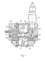
- FIG. 1 shows the longitudinal section of a possible embodiment of the ion source.
- the common anode 33 lies between the two mutually opposite cathode parts 31 and 32 of the rotationally symmetrical, focusing electrode system which is at ground potential.
- the anode 33 is designed to increase the ion current on the sample side with an asymmetrical conical anode bore 34 in its center, which widens towards the cathode part 31 on the outlet side.
- the two parts of the cavity cathode 31 and 32 are provided with a constriction 44 on the side open to the anode 33 and on the side opposite the anode 33 with a conical part 45 extending towards the anode 33.
- the cathode part 31 has on the outlet side of the ion source an inwardly widening outlet opening 46.
- the rapidly atomizing parts of the cathode system can be replaced without having to completely disassemble the ion source.
- the middle parts of the anode are exchanged bar, the retaining ring 35 is attached to the base plate 37 of the housing via intermediate porcelain insulators 36.
- the housing is made of three parts for easier maintenance.
- the middle part 38 is fastened with a threaded ring 40 to a cooling water pipe 39 holding the entire ion source, and this is also followed by a gas inlet 41.
- the base plate 37 which also carries a high-voltage connection 42, can be unscrewed together with the anode fitting.
- the cover 43 carrying the cathode part 31 can be unscrewed on the outlet side.
- a raster ion source can also be realized with one or more deflection electrodes which are attached behind the outlet side of the cathode part 31 and are not shown in FIG. 1.
- the actual diluting ion current can be measured on an insulated sample holder or the ion current value dependent thereon can be measured with the aid of a collecting electrode which is arranged either on one or the other side of the sample holder.
Landscapes
- Chemical & Material Sciences (AREA)
- Analytical Chemistry (AREA)
- Physics & Mathematics (AREA)
- General Health & Medical Sciences (AREA)
- Immunology (AREA)
- Health & Medical Sciences (AREA)
- Life Sciences & Earth Sciences (AREA)
- Biochemistry (AREA)
- Engineering & Computer Science (AREA)
- General Physics & Mathematics (AREA)
- Plasma & Fusion (AREA)
- Pathology (AREA)
- Sampling And Sample Adjustment (AREA)
- Electron Sources, Ion Sources (AREA)
- Analysing Materials By The Use Of Radiation (AREA)
- Crystals, And After-Treatments Of Crystals (AREA)
- Welding Or Cutting Using Electron Beams (AREA)
Priority Applications (1)
| Application Number | Priority Date | Filing Date | Title |
|---|---|---|---|
| AT87115673T ATE54775T1 (de) | 1983-10-12 | 1984-10-02 | Ionenquelle fuer eine einrichtung zur ionenstrahlbearbeitung, insbesondere zur bearbeitung von festkoerperproben. |
Applications Claiming Priority (2)
| Application Number | Priority Date | Filing Date | Title |
|---|---|---|---|
| HU833520A HU190855B (en) | 1983-10-12 | 1983-10-12 | Device for working solid samples by ion beam and ion source to the device |
| HU352083 | 1983-10-12 |
Related Parent Applications (1)
| Application Number | Title | Priority Date | Filing Date |
|---|---|---|---|
| EP84111775.7 Division | 1984-10-02 |
Publications (3)
| Publication Number | Publication Date |
|---|---|
| EP0267481A2 true EP0267481A2 (fr) | 1988-05-18 |
| EP0267481A3 EP0267481A3 (en) | 1988-06-08 |
| EP0267481B1 EP0267481B1 (fr) | 1990-07-18 |
Family
ID=10964368
Family Applications (2)
| Application Number | Title | Priority Date | Filing Date |
|---|---|---|---|
| EP84111775A Expired EP0141272B1 (fr) | 1983-10-12 | 1984-10-02 | Aménagement pour la fabrication d'échantillons solides par rayons ioniques |
| EP87115673A Expired - Lifetime EP0267481B1 (fr) | 1983-10-12 | 1984-10-02 | Source d'ions pour dispositif servant en particulier à l'usinage d'échantillons solides par rayons d'ions |
Family Applications Before (1)
| Application Number | Title | Priority Date | Filing Date |
|---|---|---|---|
| EP84111775A Expired EP0141272B1 (fr) | 1983-10-12 | 1984-10-02 | Aménagement pour la fabrication d'échantillons solides par rayons ioniques |
Country Status (5)
| Country | Link |
|---|---|
| EP (2) | EP0141272B1 (fr) |
| AT (2) | ATE54775T1 (fr) |
| DD (1) | DD220454A5 (fr) |
| DE (2) | DE3482778D1 (fr) |
| HU (1) | HU190855B (fr) |
Cited By (2)
| Publication number | Priority date | Publication date | Assignee | Title |
|---|---|---|---|---|
| US5472566A (en) * | 1994-11-14 | 1995-12-05 | Gatan, Inc. | Specimen holder and apparatus for two-sided ion milling system |
| WO1998013851A1 (fr) * | 1996-09-27 | 1998-04-02 | Barna Arpad | Source d'ions pour la generation des ions d'un gaz ou d'une vapeur |
Families Citing this family (4)
| Publication number | Priority date | Publication date | Assignee | Title |
|---|---|---|---|---|
| JP2779414B2 (ja) * | 1988-12-01 | 1998-07-23 | セイコーインスツルメンツ株式会社 | ミクロ断面の加工・観察方法 |
| US5089774A (en) * | 1989-12-26 | 1992-02-18 | Sharp Kabushiki Kaisha | Apparatus and a method for checking a semiconductor |
| DE102012010708B4 (de) * | 2012-05-30 | 2021-12-23 | Carl Zeiss Microscopy Gmbh | Kombiniertes bearbeitungssystem zur bearbeitung mittels laser und fokussierten ionenstrahlen |
| US8371182B1 (en) * | 2012-06-11 | 2013-02-12 | Jacob Israelachvili | Mounting systems for a surface forces apparatus |
Citations (3)
| Publication number | Priority date | Publication date | Assignee | Title |
|---|---|---|---|---|
| US3847780A (en) * | 1972-07-24 | 1974-11-12 | Rathenower Optische Werke Veb | Device for thinning technical and microscopic specimens under laminar flow conditions |
| GB1428396A (en) * | 1972-09-08 | 1976-03-17 | Atomic Energy Authority Uk | Ion sources |
| DE3045468A1 (de) * | 1980-12-02 | 1982-07-01 | Sergej Ivanovič Tomsk Beljuk | Elektronen-ionenquelle |
Family Cites Families (2)
| Publication number | Priority date | Publication date | Assignee | Title |
|---|---|---|---|---|
| GB1493133A (en) * | 1975-10-08 | 1977-11-23 | Franks J | Preparation of specimens to be examined by electron microscopy techniques |
| GB2010577B (en) * | 1977-11-07 | 1982-05-06 | Ion Tech Ltd | Preparation of materials for examination of transmission electron microscopy techniques |
-
1983
- 1983-10-12 HU HU833520A patent/HU190855B/hu not_active IP Right Cessation
-
1984
- 1984-07-18 DD DD84265397A patent/DD220454A5/de not_active IP Right Cessation
- 1984-10-02 DE DE8787115673T patent/DE3482778D1/de not_active Expired - Fee Related
- 1984-10-02 AT AT87115673T patent/ATE54775T1/de not_active IP Right Cessation
- 1984-10-02 AT AT84111775T patent/ATE39785T1/de active
- 1984-10-02 DE DE8484111775T patent/DE3475988D1/de not_active Expired
- 1984-10-02 EP EP84111775A patent/EP0141272B1/fr not_active Expired
- 1984-10-02 EP EP87115673A patent/EP0267481B1/fr not_active Expired - Lifetime
Patent Citations (3)
| Publication number | Priority date | Publication date | Assignee | Title |
|---|---|---|---|---|
| US3847780A (en) * | 1972-07-24 | 1974-11-12 | Rathenower Optische Werke Veb | Device for thinning technical and microscopic specimens under laminar flow conditions |
| GB1428396A (en) * | 1972-09-08 | 1976-03-17 | Atomic Energy Authority Uk | Ion sources |
| DE3045468A1 (de) * | 1980-12-02 | 1982-07-01 | Sergej Ivanovič Tomsk Beljuk | Elektronen-ionenquelle |
Cited By (3)
| Publication number | Priority date | Publication date | Assignee | Title |
|---|---|---|---|---|
| US5472566A (en) * | 1994-11-14 | 1995-12-05 | Gatan, Inc. | Specimen holder and apparatus for two-sided ion milling system |
| WO1998013851A1 (fr) * | 1996-09-27 | 1998-04-02 | Barna Arpad | Source d'ions pour la generation des ions d'un gaz ou d'une vapeur |
| US6236054B1 (en) | 1996-09-27 | 2001-05-22 | BARNA ARPáD | Ion source for generating ions of a gas or vapor |
Also Published As
| Publication number | Publication date |
|---|---|
| ATE54775T1 (de) | 1990-08-15 |
| HUT36612A (en) | 1985-09-30 |
| EP0141272A1 (fr) | 1985-05-15 |
| DE3475988D1 (en) | 1989-02-09 |
| EP0141272B1 (fr) | 1989-01-04 |
| ATE39785T1 (de) | 1989-01-15 |
| EP0267481A3 (en) | 1988-06-08 |
| HU190855B (en) | 1986-11-28 |
| DD220454A5 (de) | 1985-03-27 |
| EP0267481B1 (fr) | 1990-07-18 |
| DE3482778D1 (de) | 1990-08-23 |
Similar Documents
| Publication | Publication Date | Title |
|---|---|---|
| EP1385193B9 (fr) | Lentille d'objectif pour système de microscopie électronique, et système de microscopie électronique | |
| EP0334204B1 (fr) | Procédé et dispositif de revêtement d'objets | |
| DE19652021B4 (de) | Ionen-Quelle und Ionisationsverfahren | |
| DE1798021A1 (de) | Mikroanalysenvorrichtung | |
| EP1277221B1 (fr) | Canon electronique pour electrons ou faisceaux ioniques de haute monochromie ou de haute densite de courant | |
| DE2842527B2 (de) | Elektrostatische Emissionslinse | |
| DE3206882A1 (de) | Verfahren und vorrichtung zum verdampfen von material unter vakuum | |
| EP0840940B1 (fr) | Procede et dispositif pour l'amincissement ionique dans un microscope electronique a transmission haute resolution | |
| EP0558797B1 (fr) | Dispositif de pulvérisation cathodique | |
| DE102007010873B4 (de) | Objektivlinse | |
| DE4216730A1 (de) | Rasterelektronenstrahlgerät | |
| DE2520556A1 (de) | Verfahren zum selektiven entfernen von material von der oberflaeche eines werkstueckes | |
| DE1133841B (de) | Elektronenmikroskop zur direkten Abbildung von Oberflaechen durch Sekundaerelektronen, Verfahren zur Untersuchung von Nichtleitern oder Halbleitern und Anordnung zur Durchfuehrung des Verfahrens | |
| EP0267481B1 (fr) | Source d'ions pour dispositif servant en particulier à l'usinage d'échantillons solides par rayons d'ions | |
| DE112015006787B4 (de) | Ionenätzsystem | |
| DE2608958A1 (de) | Vorrichtung zum erzeugen von strahlen aus geladenen teilchen | |
| DE102008009640A1 (de) | Prozessierungssystem | |
| EP0175807B1 (fr) | Appareil pour la spectrométrie de masse de particules neutres pulvérisées | |
| DE922365C (de) | Roentgenroehre mit sehr feinem Brennfleck | |
| DE879876C (de) | Vorrichtung mit elektronenoptischer Abbildung einer photoelektrischen Kathode | |
| EP1609882A1 (fr) | Système et methode de dépot par pulverisation cathodique | |
| DE4214417C1 (en) | Plasma lens e.g. for focussing charged particle beam - has insulating wall enclosing cylindrical discharge plasma between two opposing electrodes with aligned apertures for passage of particle beam | |
| DE3511141C2 (fr) | ||
| DE2304906C2 (de) | Feldemissions-Strahlerzeugungssystem | |
| DE3513546A1 (de) | Verfahren und anordnung zum ablenken eines elektronenstrahls |
Legal Events
| Date | Code | Title | Description |
|---|---|---|---|
| PUAI | Public reference made under article 153(3) epc to a published international application that has entered the european phase |
Free format text: ORIGINAL CODE: 0009012 |
|
| PUAL | Search report despatched |
Free format text: ORIGINAL CODE: 0009013 |
|
| 17P | Request for examination filed |
Effective date: 19871026 |
|
| AC | Divisional application: reference to earlier application |
Ref document number: 141272 Country of ref document: EP |
|
| AK | Designated contracting states |
Kind code of ref document: A2 Designated state(s): AT CH DE GB LI |
|
| RHK1 | Main classification (correction) |
Ipc: H01J 37/08 |
|
| AK | Designated contracting states |
Kind code of ref document: A3 Designated state(s): AT CH DE GB LI |
|
| 17Q | First examination report despatched |
Effective date: 19891023 |
|
| GRAA | (expected) grant |
Free format text: ORIGINAL CODE: 0009210 |
|
| AC | Divisional application: reference to earlier application |
Ref document number: 141272 Country of ref document: EP |
|
| AK | Designated contracting states |
Kind code of ref document: B1 Designated state(s): AT CH DE GB LI |
|
| REF | Corresponds to: |
Ref document number: 54775 Country of ref document: AT Date of ref document: 19900815 Kind code of ref document: T |
|
| GBT | Gb: translation of ep patent filed (gb section 77(6)(a)/1977) | ||
| REF | Corresponds to: |
Ref document number: 3482778 Country of ref document: DE Date of ref document: 19900823 |
|
| PG25 | Lapsed in a contracting state [announced via postgrant information from national office to epo] |
Ref country code: AT Effective date: 19901002 |
|
| PLBE | No opposition filed within time limit |
Free format text: ORIGINAL CODE: 0009261 |
|
| STAA | Information on the status of an ep patent application or granted ep patent |
Free format text: STATUS: NO OPPOSITION FILED WITHIN TIME LIMIT |
|
| 26N | No opposition filed | ||
| PGFP | Annual fee paid to national office [announced via postgrant information from national office to epo] |
Ref country code: CH Payment date: 19910926 Year of fee payment: 8 |
|
| PGFP | Annual fee paid to national office [announced via postgrant information from national office to epo] |
Ref country code: GB Payment date: 19910930 Year of fee payment: 8 |
|
| PGFP | Annual fee paid to national office [announced via postgrant information from national office to epo] |
Ref country code: DE Payment date: 19911223 Year of fee payment: 8 |
|
| PG25 | Lapsed in a contracting state [announced via postgrant information from national office to epo] |
Ref country code: GB Effective date: 19921002 |
|
| PG25 | Lapsed in a contracting state [announced via postgrant information from national office to epo] |
Ref country code: LI Effective date: 19921031 Ref country code: CH Effective date: 19921031 |
|
| GBPC | Gb: european patent ceased through non-payment of renewal fee |
Effective date: 19921002 |
|
| REG | Reference to a national code |
Ref country code: CH Ref legal event code: PL |
|
| PG25 | Lapsed in a contracting state [announced via postgrant information from national office to epo] |
Ref country code: DE Effective date: 19930701 |