EP0267481A2 - Ion source for an apparatus for processing solid-state samples by means of ion beams - Google Patents
Ion source for an apparatus for processing solid-state samples by means of ion beams Download PDFInfo
- Publication number
- EP0267481A2 EP0267481A2 EP87115673A EP87115673A EP0267481A2 EP 0267481 A2 EP0267481 A2 EP 0267481A2 EP 87115673 A EP87115673 A EP 87115673A EP 87115673 A EP87115673 A EP 87115673A EP 0267481 A2 EP0267481 A2 EP 0267481A2
- Authority
- EP
- European Patent Office
- Prior art keywords
- anode
- ion
- ion source
- cathode
- sample
- Prior art date
- Legal status (The legal status is an assumption and is not a legal conclusion. Google has not performed a legal analysis and makes no representation as to the accuracy of the status listed.)
- Granted
Links
Images
Classifications
-
- G—PHYSICS
- G01—MEASURING; TESTING
- G01N—INVESTIGATING OR ANALYSING MATERIALS BY DETERMINING THEIR CHEMICAL OR PHYSICAL PROPERTIES
- G01N1/00—Sampling; Preparing specimens for investigation
- G01N1/28—Preparing specimens for investigation including physical details of (bio-)chemical methods covered elsewhere, e.g. G01N33/50, C12Q
- G01N1/32—Polishing; Etching
-
- H—ELECTRICITY
- H01—ELECTRIC ELEMENTS
- H01J—ELECTRIC DISCHARGE TUBES OR DISCHARGE LAMPS
- H01J37/00—Discharge tubes with provision for introducing objects or material to be exposed to the discharge, e.g. for the purpose of examination or processing thereof
- H01J37/02—Details
- H01J37/04—Arrangements of electrodes and associated parts for generating or controlling the discharge, e.g. electron-optical arrangement, ion-optical arrangement
- H01J37/08—Ion sources; Ion guns
-
- H—ELECTRICITY
- H01—ELECTRIC ELEMENTS
- H01J—ELECTRIC DISCHARGE TUBES OR DISCHARGE LAMPS
- H01J37/00—Discharge tubes with provision for introducing objects or material to be exposed to the discharge, e.g. for the purpose of examination or processing thereof
- H01J37/30—Electron-beam or ion-beam tubes for localised treatment of objects
- H01J37/305—Electron-beam or ion-beam tubes for localised treatment of objects for casting, melting, evaporating or etching
Definitions
- the invention relates to an ion source for a device for ion beam processing of material samples or for removing surface layers according to the preamble of claim 1.
- the ion source is suitable for generating ion beams with a small diameter / mm and a large current density.
- the common characteristic of the known devices is that two opposite, fixedly arranged ion sources are used on both sides of the material sample to be diluted, the ion sources with the also fixedly arranged, rotating in one plane sample holder can be rotated together around a tangent . So there is the possibility that the sample on both sides simultaneously, either with the optimal atomization speed / at an angle of approx. 70 ° / or with the optimal polishing angle / approx. 85 ° / is diluted. The dilution process is observed with an optical microscope attached outside the atomization chamber. Laser or other automatic process interrupters are often used.
- the devices either use cavity anode sources as ion sources (e.g.
- CG Crocket A glow discharge ion gun for etching, Vacuum 23, 11-13 / 1973 /), or mirror cathode sources combined with a magnetic field / e.g. DJ Barber: Thin Foils of Non-Metals Made for Electron Microscopy by Sputter-Etching, J. of Materials Sci. 5, 1-8 / 1970 /, or contain electrostatic saddle field sources (e.g. J. Franks: A saddle field ion source of spherical configuration for etching and thinning applications, Vacuum 24, 489-491 / 1974 /), or with an electrostatic focusing lens system provided sources of the Penning type (e.g. V. Alexander, J. Linders, HJ Lippold, H. Niedersig and T.
- electrostatic saddle field sources e.g. J. Franks: A saddle field ion source of spherical configuration for etching and thinning applications, Vacuum 24, 489-491 / 1974 /
- sources of the Penning type e
- Ion sources that do not have a focusing electrode system produce a diverging ion beam with a large diameter.
- the diameter of the ion beam at the sample location is large (2-5 mm), while the ion current density is small (0.1-1 mA / cm2), which strongly limits the atomization speed of the sample (generally only a few ⁇ / hour).
- Small ion beam diameters (a few tenths of a millimeter) can be generated by means of a Penning-type ion source having a focusing electrode system, but they have an extremely complicated structure (magnetic field, 3-5 adjustable high-voltage focusing electrodes, furthermore the required supply voltage sources), large dimensions and their cleaning is extraordinary is time consuming.
- the object of the invention is to eliminate the disadvantages mentioned above and to provide an ion source for a device for ion beam processing, which has a simple structure with small dimensions, is quick to clean and which is more advantageous in terms of its polishing properties than the previously known solutions is.
- both parts of the cavity cathode are provided with a constriction on the side open to the anode and on the side opposite the anode with a conical part which is calculated towards the anode.
- the solution according to the invention combines the property of the corresponding ion beam focusing of the mirror cathode sources and the Penning sources having a focusing electrode system, as well as the simple structure and power source claim of the hollow cathode ion sources.
- the optimal operating geometry can be set safely and easily or corrected during operation.
- the diameter of the ion beam can be selected to be less than 0.1 mm in the ion beam thinning, so that e.g. in the case of an almost grazing incidence at 87 °, the beam does not extend beyond the area to be thinned.
- the current density can be increased up to 20 mA / cm2.
- the ion source is based on the knowledge that the secondary electrons ionizing the gas introduced into the ion source are very effectively opposed by two standing electrode systems corresponding to the so-called Steigerwald electron guns known per se (KHS Steigerwald: optics 5.469 / 1947), the electrostatic lens system according to Steigerwald being based on the optical analogy (E. Brüche: Von Braun's tube to the "Fernfokus", magazine for applied physics, volume III, 88-90, 1951) corresponds to a teleoptic immersion lens system.
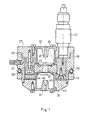
- FIG. 1 shows the longitudinal section of a possible embodiment of the ion source.
- the common anode 33 lies between the two mutually opposite cathode parts 31 and 32 of the rotationally symmetrical, focusing electrode system which is at ground potential.
- the anode 33 is designed to increase the ion current on the sample side with an asymmetrical conical anode bore 34 in its center, which widens towards the cathode part 31 on the outlet side.
- the two parts of the cavity cathode 31 and 32 are provided with a constriction 44 on the side open to the anode 33 and on the side opposite the anode 33 with a conical part 45 extending towards the anode 33.
- the cathode part 31 has on the outlet side of the ion source an inwardly widening outlet opening 46.
- the rapidly atomizing parts of the cathode system can be replaced without having to completely disassemble the ion source.
- the middle parts of the anode are exchanged bar, the retaining ring 35 is attached to the base plate 37 of the housing via intermediate porcelain insulators 36.
- the housing is made of three parts for easier maintenance.
- the middle part 38 is fastened with a threaded ring 40 to a cooling water pipe 39 holding the entire ion source, and this is also followed by a gas inlet 41.
- the base plate 37 which also carries a high-voltage connection 42, can be unscrewed together with the anode fitting.
- the cover 43 carrying the cathode part 31 can be unscrewed on the outlet side.
- a raster ion source can also be realized with one or more deflection electrodes which are attached behind the outlet side of the cathode part 31 and are not shown in FIG. 1.
- the actual diluting ion current can be measured on an insulated sample holder or the ion current value dependent thereon can be measured with the aid of a collecting electrode which is arranged either on one or the other side of the sample holder.
Abstract
Description
Die Erfindung betrifft eine Ionenquelle für eine Einrichtung zur Ionenstrahlbearbeitung von Materialproben oder zur Entfernung von Oberflächenschichten gemäß dem Oberbegriff des Anspruchs 1. Die Ionenquelle ist zur Erzeugung von Ionenstrahlen mit kleinem Durchmesser /« mm / und großer Stromdichte geeignet.The invention relates to an ion source for a device for ion beam processing of material samples or for removing surface layers according to the preamble of claim 1. The ion source is suitable for generating ion beams with a small diameter / mm and a large current density.
Die Ionenstrahlzerstäubung bei der Herstellung von Proben für die Transmissionselektronenmikroskopie wird seit etwa 1960 angewandt. (H. Dücher und W. Schlette: Über die Herstellung von durchstrahlbaren Metallfoliden durch Ionenätzung. Coll.Ing. du C.N.R.S. Nr. 1113,83-90 Bellevue/1962/). Über die Verfahren und die Verdünnungseinrichtungen kann aus den folgenden, zusammenfassenden Literaturangaben ein guter Überblick gewonnen werden;
H. Bach: Die Anwendbarkeit des Ionenstrahlätzens bei der Präparation für die Elektronenmikroskopie
G.Schimmel, W. Vogell: Methodensammlung der Elektronenmikroskopie, Wiss. Verlag MBH, Stuttgart 1970, 2.4.2.1
J. Francks: Ion Beam Technology Applied to Electron/Microscopy, /Advences in Electronics and Electron Physics, Vol.47 Ed. L. Marton: Acad.Press, New York 1978. 1.-48. Seite/.Ion beam sputtering has been used in the manufacture of samples for transmission electron microscopy since about 1960. (H. Dücher and W. Schlette: On the production of radiopaque metal foils by ion etching. Coll.Ing. Du CNRS No. 1113.83-90 Bellevue / 1962 /). A good overview of the processes and the dilution devices can be obtained from the following summarizing references;
H. Bach: The applicability of ion beam etching in preparation for electron microscopy
G.Schimmel, W. Vogell: Collection of Methods in Electron Microscopy, Wiss. Verlag MBH, Stuttgart 1970, 2.4.2.1
J. Francks: Ion Beam Technology Applied to Electron / Microscopy, / Advences in Electronics and Electron Physics, Vol.47 Ed. L. Marton: Acad.Press, New York 1978. 1-48. Page/.
Die gemeinsame Charakteristik der bekannten Einrichtungen besteht darin, daß an beiden Seiten der zu verdünnenden Materialprobe zwei einander gegenübergestellte, miteinander fix angeordnete Ionenquellen angewandt werden, wobei die Ionenquellen mit den ebenfalls fest angeordneten, sich in einer Ebene drehenden Probenhalter um eine Tangente herum gemeinsam drehbar sind. So ergibt sich die Möglichkeit dafür, daß die Probe gleichzeitig auf beiden Seiten, entweder mit der optimalen Zerstäubungsgeschwindigkeit /in einem Winkel von ca. 70°/ oder mit dem optimalen Polierwinkel /ca. 85°/ verdünnt wird. Der Verdünnungsprozeß wird mit einem außerhalb des Zerstäubungsraumes angebrachten optischen Mikroskop beobachtet. Häufig werden Laser- oder andere automatische Prozeßunterbrecher angewendet. Die Einrichtungen benutzen als Ionenquellen entweder Hohlraumanodenquellen (z.B. C.G. Crocket: A glow discharge ion gun for etching, Vacuum 23, 11-13/1973/), oder mit Magnetfeld kombinierte Spiegelkathodenquellen /z.B. D.J. Barber: Thin Foils of Non-Metalls Made for Electron Microscopy by Sputter-Etching, J. of Materials Sci. 5, 1-8/1970/, oder enthalten elektrostatische Sattelfeld-Quellen (z.B. J. Franks: A saddle field ion source of spherical configuration for etching and thinning applications, Vacuum 24, 489-491/1974/), oder mit elektrostatischem Fokussierlinsensystem versehene Quellen des Types Penning, (z.B. V. Alexander, J. Linders, H.J. Lippold, H. Niedrig and T. Sebald, "Appenning type ion source with high efficiency and some applications", Radiation Effects 59, 183-189 (1982), Kentaroh Yoshida and Takashi Yamada, "Ion thinning apparatus for the preparation of transmission electron microscopy specimens using new-type ion guns" (Rev.Sci.Instrum.,55, 551-557/ 1984), fallweise "Kaufman"-Quellen (H.R. Kaufman, J.M. E. Harper, J.J. Cuomo: Abstract: Focused ion beam designs for sputter deposition, J. Vac. Sci. Technol, 16/2, 179-180,1979).The common characteristic of the known devices is that two opposite, fixedly arranged ion sources are used on both sides of the material sample to be diluted, the ion sources with the also fixedly arranged, rotating in one plane sample holder can be rotated together around a tangent . So there is the possibility that the sample on both sides simultaneously, either with the optimal atomization speed / at an angle of approx. 70 ° / or with the optimal polishing angle / approx. 85 ° / is diluted. The dilution process is observed with an optical microscope attached outside the atomization chamber. Laser or other automatic process interrupters are often used. The devices either use cavity anode sources as ion sources (e.g. CG Crocket: A glow discharge ion gun for etching, Vacuum 23, 11-13 / 1973 /), or mirror cathode sources combined with a magnetic field / e.g. DJ Barber: Thin Foils of Non-Metals Made for Electron Microscopy by Sputter-Etching, J. of Materials Sci. 5, 1-8 / 1970 /, or contain electrostatic saddle field sources (e.g. J. Franks: A saddle field ion source of spherical configuration for etching and thinning applications, Vacuum 24, 489-491 / 1974 /), or with an electrostatic focusing lens system provided sources of the Penning type (e.g. V. Alexander, J. Linders, HJ Lippold, H. Niedersig and T. Sebald, "Appenning type ion source with high efficiency and some applications", Radiation Effects 59, 183-189 (1982) , Kentaroh Yoshida and Takashi Yamada, "Ion thinning apparatus for the preparation of transmission electron microscopy specimens using new-type ion guns" (Rev.Sci.Instrum., 55, 551-557 / 1984), occasionally "Kaufman" sources (HR Kaufman, JME Harper, JJ Cuomo: Abstract: Focused ion beam designs for sputter deposition, J. Vac. Sci. Technol, 16/2, 179-180, 1979).
Ionenquellen, die kein Fokussierelektrodensystem aufweisen, erzeugen ein divergierendes Ionenbündel mit großem Durchmesser. Da jedoch die zu bearbeitende Probe aus technischen Gründen nicht beliebig nah zu der Ionenquelle angebracht werden kann (minimal 15-20 mm von der Ionenquelle entfernt), ist der Durchmesser des Ionenstrahls an der Probenstelle groß (2-5 mm), die Ionenstromdichte dagegen klein (0,1-1 mA/cm²), wodurch die Zerstäubungsgeschwindigkeit der Probe stark begrenzt wird (im allgemeinen nur einige µ/Stunde).Ion sources that do not have a focusing electrode system produce a diverging ion beam with a large diameter. However, since the sample to be processed cannot be placed as close as possible to the ion source for technical reasons (at least 15-20 mm away from the ion source), the diameter of the ion beam at the sample location is large (2-5 mm), while the ion current density is small (0.1-1 mA / cm²), which strongly limits the atomization speed of the sample (generally only a few µ / hour).
Bei aus Materialien mit verschiedener Zerstäubungsgeschwindigkeit bestehenden zusammengesetzten Proben, des weiteren zur Minimierung der Oberflächenstrahlenbeschädigungen ist eine derartige Bearbeitung bzw. Verdünnung der Proben erforderlich, bei welcher der Ionenstrahl auf die Oberfläche der Probe unter einem annähernd streifenden Winkel auftrifft (P.J. Goodhew: Thin foil preparation for El. Micr. in Pract. Methods in El. Micr., Ed.: A.M. Glauert, Elsevier, 1985). Diese Einstellung vergrößert natürlich in der zur Kippachse senkrechten Richtung die von dem Ionenstrahl gestreifte Fläche (20-50 mm). Da die Elektronenmikroskopproben einen Durchmesser von 2-3 mm aufweisen, zerstäubt der Ionenstrahl in erster Linie die Probenhalterung und nicht die Probe. Kleine Ionenstrahldurchmesser (einige Zehntel Millimeter) können zwar mittels ein Fokussierelektrodensystem aufweisenden Ionenquellen des Penning-Types erzeugt werden, die jedoch einen äußerst komplizierten Aufbau aufweisen (Magnetfeld, 3-5 regelbare Hochspannungsfokussierelektroden, desweiteren die erforderlichen Speisespannungsquellen), große Abmessungen haben und deren Reinigung außerordentlich zeitaufwendig ist.In the case of composite samples consisting of materials with different atomization speeds, furthermore in order to minimize the damage to the surface radiation, such processing or thinning of the samples is necessary in which the ion beam strikes the surface of the sample at an approximately grazing angle (PJ Goodhew: Thin foil preparation for El. Micr. In Pract. Methods in El. Micr., Ed .: AM Glauert, Elsevier, 1985). This setting naturally increases the area streaked by the ion beam (20-50 mm) in the direction perpendicular to the tilt axis. Since the electron microscope samples have a diameter of 2-3 mm, the ion beam primarily atomizes the sample holder and not the sample. Small ion beam diameters (a few tenths of a millimeter) can be generated by means of a Penning-type ion source having a focusing electrode system, but they have an extremely complicated structure (magnetic field, 3-5 adjustable high-voltage focusing electrodes, furthermore the required supply voltage sources), large dimensions and their cleaning is extraordinary is time consuming.
Die Aufgabe der Erfindung besteht darin, die oben genannten Nachteile zu beseitigen und eine Ionenquelle für eine Einrichtung zur Ionenstrahlbearbeitung zu schaffen, die einen einfachen Aufbau mit kleinen Abmessungen aufweist, schnell zu reinigen ist und die im Hinblick auf ihre Poliereigenschaften vorteilhafter als die bisher bekannten Lösungen ist.The object of the invention is to eliminate the disadvantages mentioned above and to provide an ion source for a device for ion beam processing, which has a simple structure with small dimensions, is quick to clean and which is more advantageous in terms of its polishing properties than the previously known solutions is.
Diese Aufgabe wird erfindungsgemäß dadurch gelöst, daß beide Teile der Hohlraumkathode auf der zur Anode geöffneten Seite mit einer Verengung versehen sind und auf der der Anode gegenüberliegenden Seite mit einem sich zur Anode hin erstrechenden konischen Teil.This object is achieved in that both parts of the cavity cathode are provided with a constriction on the side open to the anode and on the side opposite the anode with a conical part which is calculated towards the anode.
Die erfindungsgemäße Lösung vereint in sich die Eigenschaft der entsprechenden Ionenbündelfokussierung der Spiegelkathodenquellen und der ein Fokussierelektrodensystem aufweisenden Penning-Quellen, sowie den einfachen Aufbau und Speisequellenanspruch der Hohlraumkathoden-Ionenquellen.The solution according to the invention combines the property of the corresponding ion beam focusing of the mirror cathode sources and the Penning sources having a focusing electrode system, as well as the simple structure and power source claim of the hollow cathode ion sources.
Mit Hilfe der Erfindung kann die optimale Betriebsgeometrie sicher und leicht eingestellt bzw. während des Betriebes korrigiert werden.With the help of the invention, the optimal operating geometry can be set safely and easily or corrected during operation.
Unter diesen Umständen kann bei der Ionenstrahlverdünnung der Durchmesser des Ionenstrahles kleiner als 0,1 mm gewählt werden, so daß z.B. im Falle eines bei 87° liegenden, fast streifenden Einfalles der Strahl nicht über das zu verdünnende Gebiet hinausreicht. Dagegen kann gleichzeitig im Interesse einer schnelleren Verdünnung der Probe, ohne eine bedeutende Erwärmung der Probe und des Probenhalters, die Stromdichte bis zu 20 mA/cm² gesteigert werden.Under these circumstances, the diameter of the ion beam can be selected to be less than 0.1 mm in the ion beam thinning, so that e.g. in the case of an almost grazing incidence at 87 °, the beam does not extend beyond the area to be thinned. On the other hand, in the interest of a faster dilution of the sample, without significant heating of the sample and the sample holder, the current density can be increased up to 20 mA / cm².
Die Ionenquelle beruht auf der Erkenntnis, daß die das in die Ionenquelle eingeleitete Gas ionisierenden Sekundärelektronen sehr wirksam durch zwei einander gegenüber stehende, den an sich bekannten sog. Steigerwald-Elektronenkanonen entsprechende Elektrodensysteme fokussiert werden könne, (K.H.Steigerwald: Optik 5,469/1947), wobei das elektrostatische Linsensystem nach Steigerwald anhand der optischen Analogie (E. Brüche: Von Brauns Röhre zum "Fernfokus", Zeitschrift für angew. Physik, Band III, 88-90, 1951) einem teleoptischen Immersions-Linsensystem entspricht.The ion source is based on the knowledge that the secondary electrons ionizing the gas introduced into the ion source are very effectively opposed by two standing electrode systems corresponding to the so-called Steigerwald electron guns known per se (KHS Steigerwald: optics 5.469 / 1947), the electrostatic lens system according to Steigerwald being based on the optical analogy (E. Brüche: Von Braun's tube to the "Fernfokus", magazine for applied physics, volume III, 88-90, 1951) corresponds to a teleoptic immersion lens system.
Nachstehend wird die Erfindung anhand einer vorteilhaften Ausführungsform mit Bezugnahme auf die Zeichnung näher erläutert. Dabei zeigt die
- Fig. 1 eine Längsschnittansicht der erfindungsgemäßen Ionenquelle.
- Fig. 1 is a longitudinal sectional view of the ion source according to the invention.
Die Figur 1 zeigt den Längsschnitt einer möglichen Ausführungsform der Ionenquelle. Die gemeinsame Anode 33 liegt zwischen den beiden sich einander gegenüberstehenden Kathodenteilen 31 und 32 des auf Erdpotential liegenden drehsymmetrischen, fokussierenden Elektrodensystems. Die Anode 33 ist zur Erhöhung des Ionenstromes an der Probenseite mit einer assymmetrischen konischen Anodenbohrung 34 in ihrer Mitte ausgebildet, welche sich zu dem auf der Austrittsseite liegenden Kathodenteil 31 hin erweitert. Die beiden Teile der Hohlraumkathode 31 und 32 sind auf der zur Anode 33 geöffneten Seite mit einer Verengung 44 versehen und auf der der Anode 33 gegenüberliegenden Seite mit einem sich zur Anode 33 hin erstreckenden konischen Teil 45. Der Kathodenteil 31 weist auf der Austrittsseite der Ionenquelle eine sich nach innen verbreitende Austrittsöffnung 46 auf.FIG. 1 shows the longitudinal section of a possible embodiment of the ion source. The
Die schnell zerstäubenden Teile des Kathodensystems sind austauschbar, ohne daß die Ionenquelle hierfür vollständig auseinandergenommen werden muß. In ähnlicher Weise sind die mittleren Teile der Anode austausch bar, deren Haltering 35 über zwischengeschaltete Porzellanisolatoren 36 an der Grundplatte 37 des Gehäuses befestigt ist. Zum leichteren Instandhalten ist das Gehäuse aus drei Teilen ausgebildet. Von diesen ist der mittlere Teil 38 mit einem Gewindering 40 an einem, die ganze Ionenquelle haltenden Kühlwasserrohr 39 befestigt und daran schließt sich auch eine Gaseinführung 41 an. Die Grundplatte 37, die auch einen Hochspannungsanschluß 42 trägt, kann mit der Anodenarmatur gemeinsam ausgeschraubt werden. Ähnlich ist auf der Austrittsseite der den Kathodenteil 31 tragende Deckel 43 ausschraubbar.The rapidly atomizing parts of the cathode system can be replaced without having to completely disassemble the ion source. Similarly, the middle parts of the anode are exchanged bar, the
Wie durchgeführte Experimente zeigen, bildet sich in der auf diese Weise hergestellten Ionenquelle ein ionisierter Kanal mit kleinem Durchmesser und großer Stromdichte, woraus folgt, daß der austretende Ionenstrahl ebenfalls einen kleinen Durchmesser hat, sich kaum ausbreitet, d.h. kaum streut und die erforderliche Stromdichte leicht sichergestellt werden kann, um z.B. eine Geschwindigkeit von etwa 50 µ/Stunde bei Si zu erreichen. Es kann auch mit einer oder mehreren Ablenkungseltkroden, die hinter der Austrittsseite des Kathodenteils 31 angebracht sind und in der Fig. 1 nicht dargestellt sind, eine Raster-Ionenquelle verwirklicht werden. Der tatsächliche verdünnende Ionenstrom kann auf einem isolierten Probenhalter oder der von ihm abhängige Ionenstromwert kann mit Hilfe einer Auffangelektrode gemessen werden, die entweder auf der einen oder anderen Seite des Probenhalters angeordnet ist, gemessen werden.As experiments carried out show, an ionized channel with a small diameter and a large current density forms in the ion source produced in this way, from which it follows that the emerging ion beam also has a small diameter, hardly spreads, i.e. hardly scatters and the required current density can be easily ensured, e.g. to achieve a speed of about 50 µ / hour for Si. A raster ion source can also be realized with one or more deflection electrodes which are attached behind the outlet side of the
Durch die erfindungsgemäße Ionenquelle werden folgende vorteilhafte Eigenschaften erzielt:
- a) Es können zwei Ionenquellen in bezug zu einer Probe und in bezug aufeinander schwenkbar und voneinander unabhängig zentrierbar angeordnet werden. Dadurch wird ermöglicht, daß
- die beiden sich gegenüberstehenden Ionenquellen bei gleichzeitigem Betrieb sowohl von der Vorderseite als auch von der Rückseite die Probe verdünnen,
- die Probe bei zweckmäßiger Anwendung des aus den Ionenquellen austretenden schmalen Ionenstrahles mit großer Stromdichte bei Beschuß unter einem kleinen Winkel, bezogen auf ihre Berührungsebene, nur auf der entsprechenden Stelle vom Ionenstrahl berührt wird, so daß neben der hohen Zerstäubungsgeschwindigkeit die Strahlenbelastung der Probe gering bleibt,
- mit den beiden, sich einander gegenüberstehenden Ionenkanonen bei einer von einer Seite verdünnten Probe, wo der Drehmittelpunkt des Probenhalters gegenüber dem Angriffspunkt der Ionenstrahlen verschoben ist, ein Ringbereich in die Probe geätzt werden kann. (Im Falle einer Quelle ergibt sich eine Oberflächenstruktur, die Transmissionselektronenmikroskopuntersuchungen stört). - b) Der Probenhalter kann senkrecht zur Ionenkanone verschoben werden und ist an seiner Achse entlang drehbar, weiterhin kann innerhalb des Probenhalters der Drehmittelpunkt der zu verdünnenden Probe eingestellt werden. Dies ermöglicht:
- die Kontrolle der Zerstäubung an der Probenrückseite mit einem optischen Mikroskop,
- gemeinsam mit der erwähnten Ätzmöglichkeit des Ringbereiches bzw. bei Berücksichtigung der Intensitätsverteilung des Ionenstrahles die Ausbildung eines Untersuchungsbereiches für die Transmissionselektronenmikriskopie mit relativ großem Durchmesser (≦ 0,5 mm),
- die Verdünnung eines nicht unbedingt in der Probenmitte liegenden, vorher ausgewählten Gebietes (Zielpräparierung). - c) Der durch die Einwirkung des Ionenstrahles leuchtende Probenhalter ermöglicht die genaue Einstellung der Ionenkanonen bzw. der Lage des Probenhalters, bzw. die schnelle Korrigierung der während des Betriebes durch Ladungseinwirkungen erfolgenden Ionenstrahlverschiebungen.
- a) Two ion sources can be arranged with respect to a sample and pivotable with respect to one another and can be centered independently of one another. Thereby is enabled that
the two opposing ion sources dilute the sample from both the front and the rear while operating simultaneously,
- The sample when the narrow ion beam emerging from the ion sources with a high current density is expediently bombarded at a small angle, with respect to its contact plane, is only touched by the ion beam at the appropriate point, so that in addition to the high atomization speed, the radiation exposure of the sample remains low ,
a ring area can be etched into the sample with the two mutually opposing ion cannons in a sample diluted from one side, where the center of rotation of the sample holder is shifted relative to the point of attack of the ion beams. (In the case of a source, there is a surface structure that interferes with transmission electron microscope examinations). - b) The sample holder can be moved perpendicular to the ion gun and can be rotated along its axis. Furthermore, the center of rotation of the sample to be diluted can be set within the sample holder. This makes possible:
control of the atomization on the back of the sample with an optical microscope,
- together with the mentioned possibility of etching the ring area or taking into account the intensity distribution of the ion beam, the formation of an examination area for the transmission electron microscopy with a relatively large diameter (≦ 0.5 mm),
- the dilution of a previously selected area that is not necessarily in the middle of the sample (target preparation). - c) The sample holder, which is illuminated by the action of the ion beam, enables the precise setting of the ion guns or the position of the sample holder, or the rapid correction of the ion beam displacements that occur during operation due to the effects of charges.
- 31, 32 Kathodenteil31, 32 cathode part
- 33 Anode33 anode
- 34 Anodenbohrung34 anode bore
- 35 Haltering35 retaining ring
- 36 Porzellanisolatoren36 porcelain insulators
- 37 Grundplatte37 base plate
- 38 mittlerer Teil38 middle part
- 39 Kühlwasserrohr39 cooling water pipe
- 40 Gewindering40 threaded ring
- 41 Gaseinleitung41 Gas introduction
- 42 Hochspannungsanschluß42 high-voltage connection
- 43 Deckel43 cover
- 44 Verengung44 narrowing
- 45 konischer Teil45 conical part
- 46 Austrittsöffnung46 outlet opening
Claims (4)
Priority Applications (1)
| Application Number | Priority Date | Filing Date | Title |
|---|---|---|---|
| AT87115673T ATE54775T1 (en) | 1983-10-12 | 1984-10-02 | ION SOURCE FOR A DEVICE FOR ION BEAM PROCESSING, IN PARTICULAR FOR PROCESSING SOLID SAMPLES. |
Applications Claiming Priority (2)
| Application Number | Priority Date | Filing Date | Title |
|---|---|---|---|
| HU352083 | 1983-10-12 | ||
| HU833520A HU190855B (en) | 1983-10-12 | 1983-10-12 | Device for working solid samples by ion beam and ion source to the device |
Related Parent Applications (1)
| Application Number | Title | Priority Date | Filing Date |
|---|---|---|---|
| EP84111775.7 Division | 1984-10-02 |
Publications (3)
| Publication Number | Publication Date |
|---|---|
| EP0267481A2 true EP0267481A2 (en) | 1988-05-18 |
| EP0267481A3 EP0267481A3 (en) | 1988-06-08 |
| EP0267481B1 EP0267481B1 (en) | 1990-07-18 |
Family
ID=10964368
Family Applications (2)
| Application Number | Title | Priority Date | Filing Date |
|---|---|---|---|
| EP84111775A Expired EP0141272B1 (en) | 1983-10-12 | 1984-10-02 | Apparatus for processing solid state samples with ion beams |
| EP87115673A Expired - Lifetime EP0267481B1 (en) | 1983-10-12 | 1984-10-02 | Ion source for an apparatus for processing solid-state samples by means of ion beams |
Family Applications Before (1)
| Application Number | Title | Priority Date | Filing Date |
|---|---|---|---|
| EP84111775A Expired EP0141272B1 (en) | 1983-10-12 | 1984-10-02 | Apparatus for processing solid state samples with ion beams |
Country Status (5)
| Country | Link |
|---|---|
| EP (2) | EP0141272B1 (en) |
| AT (2) | ATE39785T1 (en) |
| DD (1) | DD220454A5 (en) |
| DE (2) | DE3475988D1 (en) |
| HU (1) | HU190855B (en) |
Cited By (2)
| Publication number | Priority date | Publication date | Assignee | Title |
|---|---|---|---|---|
| US5472566A (en) * | 1994-11-14 | 1995-12-05 | Gatan, Inc. | Specimen holder and apparatus for two-sided ion milling system |
| WO1998013851A1 (en) * | 1996-09-27 | 1998-04-02 | Barna Arpad | Ion source for generating ions of a gas or vapour |
Families Citing this family (4)
| Publication number | Priority date | Publication date | Assignee | Title |
|---|---|---|---|---|
| JP2779414B2 (en) * | 1988-12-01 | 1998-07-23 | セイコーインスツルメンツ株式会社 | Processing and observation method of micro section |
| US5089774A (en) * | 1989-12-26 | 1992-02-18 | Sharp Kabushiki Kaisha | Apparatus and a method for checking a semiconductor |
| DE102012010708B4 (en) * | 2012-05-30 | 2021-12-23 | Carl Zeiss Microscopy Gmbh | COMBINED PROCESSING SYSTEM FOR PROCESSING USING LASER AND FOCUSED ION BEAMS |
| US8371182B1 (en) * | 2012-06-11 | 2013-02-12 | Jacob Israelachvili | Mounting systems for a surface forces apparatus |
Citations (3)
| Publication number | Priority date | Publication date | Assignee | Title |
|---|---|---|---|---|
| US3847780A (en) * | 1972-07-24 | 1974-11-12 | Rathenower Optische Werke Veb | Device for thinning technical and microscopic specimens under laminar flow conditions |
| GB1428396A (en) * | 1972-09-08 | 1976-03-17 | Atomic Energy Authority Uk | Ion sources |
| DE3045468A1 (en) * | 1980-12-02 | 1982-07-01 | Sergej Ivanovič Tomsk Beljuk | Ring type electron gun - has ring anode aperture displaced with respect to cathode aperture axis |
Family Cites Families (2)
| Publication number | Priority date | Publication date | Assignee | Title |
|---|---|---|---|---|
| GB1493133A (en) * | 1975-10-08 | 1977-11-23 | Franks J | Preparation of specimens to be examined by electron microscopy techniques |
| GB2010577B (en) * | 1977-11-07 | 1982-05-06 | Ion Tech Ltd | Preparation of materials for examination of transmission electron microscopy techniques |
-
1983
- 1983-10-12 HU HU833520A patent/HU190855B/en not_active IP Right Cessation
-
1984
- 1984-07-18 DD DD84265397A patent/DD220454A5/en not_active IP Right Cessation
- 1984-10-02 DE DE8484111775T patent/DE3475988D1/en not_active Expired
- 1984-10-02 DE DE8787115673T patent/DE3482778D1/en not_active Expired - Fee Related
- 1984-10-02 EP EP84111775A patent/EP0141272B1/en not_active Expired
- 1984-10-02 AT AT84111775T patent/ATE39785T1/en active
- 1984-10-02 EP EP87115673A patent/EP0267481B1/en not_active Expired - Lifetime
- 1984-10-02 AT AT87115673T patent/ATE54775T1/en not_active IP Right Cessation
Patent Citations (3)
| Publication number | Priority date | Publication date | Assignee | Title |
|---|---|---|---|---|
| US3847780A (en) * | 1972-07-24 | 1974-11-12 | Rathenower Optische Werke Veb | Device for thinning technical and microscopic specimens under laminar flow conditions |
| GB1428396A (en) * | 1972-09-08 | 1976-03-17 | Atomic Energy Authority Uk | Ion sources |
| DE3045468A1 (en) * | 1980-12-02 | 1982-07-01 | Sergej Ivanovič Tomsk Beljuk | Ring type electron gun - has ring anode aperture displaced with respect to cathode aperture axis |
Cited By (3)
| Publication number | Priority date | Publication date | Assignee | Title |
|---|---|---|---|---|
| US5472566A (en) * | 1994-11-14 | 1995-12-05 | Gatan, Inc. | Specimen holder and apparatus for two-sided ion milling system |
| WO1998013851A1 (en) * | 1996-09-27 | 1998-04-02 | Barna Arpad | Ion source for generating ions of a gas or vapour |
| US6236054B1 (en) | 1996-09-27 | 2001-05-22 | BARNA ARPáD | Ion source for generating ions of a gas or vapor |
Also Published As
| Publication number | Publication date |
|---|---|
| EP0267481B1 (en) | 1990-07-18 |
| DD220454A5 (en) | 1985-03-27 |
| EP0141272B1 (en) | 1989-01-04 |
| EP0141272A1 (en) | 1985-05-15 |
| ATE54775T1 (en) | 1990-08-15 |
| EP0267481A3 (en) | 1988-06-08 |
| HUT36612A (en) | 1985-09-30 |
| DE3482778D1 (en) | 1990-08-23 |
| ATE39785T1 (en) | 1989-01-15 |
| HU190855B (en) | 1986-11-28 |
| DE3475988D1 (en) | 1989-02-09 |
Similar Documents
| Publication | Publication Date | Title |
|---|---|---|
| EP1385193B9 (en) | Objective lens for an electron microscopy system, and electron microscopy system | |
| EP0334204B1 (en) | Process and apparatus for coating articles | |
| DE19652021B4 (en) | Ion source and ionization process | |
| DE1798021A1 (en) | Microanalysis device | |
| EP1277221B1 (en) | Electron/ion gun for electron or ion beams with high monochromasy or high current density | |
| DE2842527B2 (en) | Electrostatic emission lens | |
| DE3206882A1 (en) | METHOD AND DEVICE FOR EVAPORATING MATERIAL UNDER VACUUM | |
| EP0840940B1 (en) | Process and device for ion thinning in a high-resolution transmission electron microscope | |
| EP0558797B1 (en) | Cathodic sputtering device | |
| DE102007010873B4 (en) | objective lens | |
| DE4216730A1 (en) | Scanning electron beam appts. esp. electron beam test device or scanning electron microscope - has deflector for secondary electron beam in form of electrostatic mirror and detects secondary beam using spectrometer | |
| DE2520556A1 (en) | METHOD FOR SELECTIVE REMOVAL OF MATERIAL FROM THE SURFACE OF A WORKPIECE | |
| DE1133841B (en) | Electron microscope for the direct imaging of surfaces by secondary electrons, method for examining non-conductors or semiconductors and arrangement for carrying out the method | |
| EP0267481B1 (en) | Ion source for an apparatus for processing solid-state samples by means of ion beams | |
| DE112015006787B4 (en) | Ion etching system | |
| DE2608958A1 (en) | DEVICE FOR GENERATING RAYS FROM CHARGED PARTICLES | |
| DE102008009640A1 (en) | processing system | |
| EP0175807B1 (en) | Apparatus for the sputtered neutral mass spectrometry | |
| DE922365C (en) | X-ray tube with a very fine focal point | |
| DE879876C (en) | Device with electron-optical imaging of a photoelectric cathode | |
| DE4214417C1 (en) | Plasma lens e.g. for focussing charged particle beam - has insulating wall enclosing cylindrical discharge plasma between two opposing electrodes with aligned apertures for passage of particle beam | |
| DE3511141C2 (en) | ||
| DE2304906C2 (en) | Field emission beam generating system | |
| DE3513546A1 (en) | Method and arrangement for deflecting an electron beam | |
| EP0608478A2 (en) | Device for cathodic sputtering |
Legal Events
| Date | Code | Title | Description |
|---|---|---|---|
| PUAI | Public reference made under article 153(3) epc to a published international application that has entered the european phase |
Free format text: ORIGINAL CODE: 0009012 |
|
| PUAL | Search report despatched |
Free format text: ORIGINAL CODE: 0009013 |
|
| 17P | Request for examination filed |
Effective date: 19871026 |
|
| AC | Divisional application: reference to earlier application |
Ref document number: 141272 Country of ref document: EP |
|
| AK | Designated contracting states |
Kind code of ref document: A2 Designated state(s): AT CH DE GB LI |
|
| RHK1 | Main classification (correction) |
Ipc: H01J 37/08 |
|
| AK | Designated contracting states |
Kind code of ref document: A3 Designated state(s): AT CH DE GB LI |
|
| 17Q | First examination report despatched |
Effective date: 19891023 |
|
| GRAA | (expected) grant |
Free format text: ORIGINAL CODE: 0009210 |
|
| AC | Divisional application: reference to earlier application |
Ref document number: 141272 Country of ref document: EP |
|
| AK | Designated contracting states |
Kind code of ref document: B1 Designated state(s): AT CH DE GB LI |
|
| REF | Corresponds to: |
Ref document number: 54775 Country of ref document: AT Date of ref document: 19900815 Kind code of ref document: T |
|
| GBT | Gb: translation of ep patent filed (gb section 77(6)(a)/1977) | ||
| REF | Corresponds to: |
Ref document number: 3482778 Country of ref document: DE Date of ref document: 19900823 |
|
| PG25 | Lapsed in a contracting state [announced via postgrant information from national office to epo] |
Ref country code: AT Effective date: 19901002 |
|
| PLBE | No opposition filed within time limit |
Free format text: ORIGINAL CODE: 0009261 |
|
| STAA | Information on the status of an ep patent application or granted ep patent |
Free format text: STATUS: NO OPPOSITION FILED WITHIN TIME LIMIT |
|
| 26N | No opposition filed | ||
| PGFP | Annual fee paid to national office [announced via postgrant information from national office to epo] |
Ref country code: CH Payment date: 19910926 Year of fee payment: 8 |
|
| PGFP | Annual fee paid to national office [announced via postgrant information from national office to epo] |
Ref country code: GB Payment date: 19910930 Year of fee payment: 8 |
|
| PGFP | Annual fee paid to national office [announced via postgrant information from national office to epo] |
Ref country code: DE Payment date: 19911223 Year of fee payment: 8 |
|
| PG25 | Lapsed in a contracting state [announced via postgrant information from national office to epo] |
Ref country code: GB Effective date: 19921002 |
|
| PG25 | Lapsed in a contracting state [announced via postgrant information from national office to epo] |
Ref country code: LI Effective date: 19921031 Ref country code: CH Effective date: 19921031 |
|
| GBPC | Gb: european patent ceased through non-payment of renewal fee |
Effective date: 19921002 |
|
| REG | Reference to a national code |
Ref country code: CH Ref legal event code: PL |
|
| PG25 | Lapsed in a contracting state [announced via postgrant information from national office to epo] |
Ref country code: DE Effective date: 19930701 |