EP1385193B9 - Objective lens for an electron microscopy system, and electron microscopy system - Google Patents
Objective lens for an electron microscopy system, and electron microscopy system Download PDFInfo
- Publication number
- EP1385193B9 EP1385193B9 EP03016238A EP03016238A EP1385193B9 EP 1385193 B9 EP1385193 B9 EP 1385193B9 EP 03016238 A EP03016238 A EP 03016238A EP 03016238 A EP03016238 A EP 03016238A EP 1385193 B9 EP1385193 B9 EP 1385193B9
- Authority
- EP
- European Patent Office
- Prior art keywords
- objective lens
- pole shoe
- pole piece
- outer pole
- terminal electrode
- Prior art date
- Legal status (The legal status is an assumption and is not a legal conclusion. Google has not performed a legal analysis and makes no representation as to the accuracy of the status listed.)
- Expired - Lifetime
Links
Images


Classifications
-
- H—ELECTRICITY
- H01—ELECTRIC ELEMENTS
- H01J—ELECTRIC DISCHARGE TUBES OR DISCHARGE LAMPS
- H01J37/00—Discharge tubes with provision for introducing objects or material to be exposed to the discharge, e.g. for the purpose of examination or processing thereof
- H01J37/02—Details
- H01J37/04—Arrangements of electrodes and associated parts for generating or controlling the discharge, e.g. electron-optical arrangement, ion-optical arrangement
- H01J37/10—Lenses
- H01J37/145—Combinations of electrostatic and magnetic lenses
-
- H—ELECTRICITY
- H01—ELECTRIC ELEMENTS
- H01J—ELECTRIC DISCHARGE TUBES OR DISCHARGE LAMPS
- H01J2237/00—Discharge tubes exposing object to beam, e.g. for analysis treatment, etching, imaging
- H01J2237/26—Electron or ion microscopes
- H01J2237/28—Scanning microscopes
- H01J2237/2813—Scanning microscopes characterised by the application
- H01J2237/2817—Pattern inspection
-
- H—ELECTRICITY
- H01—ELECTRIC ELEMENTS
- H01J—ELECTRIC DISCHARGE TUBES OR DISCHARGE LAMPS
- H01J2237/00—Discharge tubes exposing object to beam, e.g. for analysis treatment, etching, imaging
- H01J2237/30—Electron or ion beam tubes for processing objects
- H01J2237/317—Processing objects on a microscale
- H01J2237/3174—Etching microareas
- H01J2237/31745—Etching microareas for preparing specimen to be viewed in microscopes or analyzed in microanalysers
-
- H—ELECTRICITY
- H01—ELECTRIC ELEMENTS
- H01J—ELECTRIC DISCHARGE TUBES OR DISCHARGE LAMPS
- H01J2237/00—Discharge tubes exposing object to beam, e.g. for analysis treatment, etching, imaging
- H01J2237/30—Electron or ion beam tubes for processing objects
- H01J2237/317—Processing objects on a microscale
- H01J2237/31749—Focused ion beam
Definitions
- the invention relates to an electron microscopy system with magnetic and electrostatic focusing, and more particularly to an objective lens for such a system. Further, the invention relates to an inspection system for imaging and manipulating an object comprising such an electron microscopy system.
- a technique is to "mill" a trench in the structure to be characterized in order to examine a cross section through the structure and so with relatively little Workload to be able to receive a wealth of information, eg regarding the sequence of layers in the structure.
- Such a trench is etched into the semiconductor structure, for example with the aid of a focused ion beam (FIB).
- FIB focused ion beam
- This etching method is of particular importance for the production of sample cross-sections for transmission electron microscopy or in the case of a structure having a complex layer sequence and different etching selectivity of the individual layers.
- Methods using a FIB allow for the production of quite fine and well-defined cuts. It is advantageous in this method to observe the etching process in situ microscopically.
- Such an objective lens which has proved to be advantageous, provides a combination of magnetic and electrostatic focusing or delay.
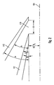
- FIG. 1 An example of a conventional objective lens is shown in FIG FIG. 1 shown schematically.
- the objective lens 1 comprises a rotationally symmetrical about an optical axis 2 of the objective lens arranged magnetic lens with a Polschuhan extract with an inner pole piece 11 and an outer pole piece 12 and with a arranged in a space between the inner and outer pole piece 11, 12 bobbin 15.
- the The objective lens 1 is an electrostatic immersion lens having a beam tube 13 forming a first electrode and a termination electrode 14.
- the beam tube 13 is disposed substantially in a lower portion of an inner space formed by the inner pole piece 11, while the termination electrode 14 is spatially substantially in the z direction connects to the outer pole piece.
- the pole shoe material carries a large part of the river.
- Magnetic field strength and extension of the magnetic field on the optical axis 2 are of importance for the focal length.
- the focal length is proportional to the acceleration voltage of the electrons divided by the spatial integral over the square of the magnetic flux density in the region of the pole pieces along the z-axis.
- a positive voltage is applied, while the termination electrode 14 is preferably connected to ground potential.
- the electrostatic lens generates a retarding field in which the electrons of the electron beam are decelerated before leaving the electron optics. This allows the electrons of the electron beam to pass through most of the beam path between the electron source and the electrostatic lens at high energy and speed, thus minimizing the negative impact electrostatic repulsion phenomena of the like charged electrons.
- the electrostatic field between the end of the tube and the end electrode 14 also has an inhomogeneity such that this field also acts focusing on the primary electrons passing through it.
- An electron microscope device comprising such an objective lens has also been advantageously employed in an arrangement for imaging and manipulating an object additionally comprising an apparatus for generating and controlling a focused ion beam (hereinafter also referred to as an ion beam processing system or FIB pillar).
- an arrangement for mapping and editing of the structure to be carried out simultaneously Due to the space requirement of the above-described objective lens of the electron-optical arrangement and the FIB column, a surface-extended object to be examined can be arranged with simultaneous imaging and processing at a maximum angle of 80 ° relative to the ion beam.
- a surface-extended object to be examined can be arranged with simultaneous imaging and processing at a maximum angle of 80 ° relative to the ion beam.
- vertical-wall trenches in an object can not be generated simultaneously with the electron microscope. Rather, after an operation to process the object by the FIB, the object is tilted and rotated, and then the structure produced by the FIB is mapped.
- a magnetic field in the region of the object manipulated by the ion beam is to be minimized because the ions are deflected by the magnetic field, resulting in deterioration of the machining precision of the focused ion beam. Furthermore, in such a magnetic field, a splitting of the ion beam into isotopes may occur, which possibly completely precludes its usability.
- the objective lens further comprises a bobbin disposed in a space between the inner and outer pole pieces.
- the geometry and arrangement of the components of the conventional objective lens have been changed to accommodate a first aspect so as to be able to reduce the angle between the conical outer pole piece and the z-axis and thus to reduce the space requirement of the objective lens and thus electron microscopic arrangement.
- a substantially flat-extended object can be more tilted with respect to the optical axis of the electron microscope arrangement.
- the working distance is to be understood here as the distance between a lowermost region or a lower end of the terminating electrode and the object plane or an object arranged in the latter, whereby a resolution-best imaging can be achieved or a resolution can be achieved at this working distance when used as intended which is not significantly different from the specified resolution when used as intended.
- the objective lens can be advantageously used even when using larger working distances.
- the latter At a lowest point in the z-direction of the inner pole piece, the latter has a gap distance oriented in the z-direction from the outer pole piece, where a pole shoe gap is formed between the inner and outer pole piece.
- the magnetic field exits in the direction of the optical axis.
- the dimensions of the Polschuhspalts have an influence on the strength as well as the spatial extent of the magnetic field on the optical axis and thus on the focal length of the objective lens.
- the characteristics of spherical and chromatic aberration must be balanced against the focusing power that is reduced by the field flattening due to material saturation or too large a gap width.
- a Polschuhspaltabstand of at least 3 mm When specifying this distance, it should be noted that this is effectively an effective Polschuhspaltabstand. That means, that it is possible, by adding additional material in the form of, for example, a thin extension or thin films or foils, to reduce the pole shoe gap or pole shoe spacing under a geometrical but not under a functional aspect. Because of this added material, the magnetic field generated by the magnetic lens, and thus the magnetic flux lines emanating from the inner and outer pole pieces, are not significantly affected by magnetic saturation in the added material, or the material is added at a point where there is hardly any flow at all located in the pole piece.
- an inner and an outer side of the inner pole piece extend upward from a lowest point of the inner pole piece in the z-direction in a conical shape.
- the inner pole piece is designed such that it extends from its lower end in the form of a cylinder jacket about 1 mm to 3 mm in the z-direction upwards, before it widens conically at least on an outer side.
- the outer pole piece tapers downwards.
- the inner pole piece at least at its lower end an inner diameter of 6 mm to 8 mm, with an inner diameter of 7.5 mm is particularly preferred.
- the dimension of the radially innermost axially lowermost portion of the outer pole piece located axially about the axis is preferably in a range of 0.5 mm to 3 mm, the dimension of the radially innermost axially axially disposed lowest portion of the inner pole piece is preferably 10 mm and more.
- a lower end of the terminal electrode in the z-direction is spaced from a z-direction lowermost region of the outer pole piece in the z-direction.
- the jet pipe is arranged such that it at least passes through an opening of the outer pole shoe formed by a region of the outer pole shoe that is the lowest in the z direction.
- the jet pipe passes through the opening of the outer pole piece and the lower end of the steel tube is arranged so that it is spaced in the z-direction from the opening of the outer pole piece, ie parallel to the optical axis extending from the pole piece, in particular the opening of the outer pole piece emerges.
- the lower end of the jet pipe in the z-direction is particularly preferred between the opening of the outer pole piece and the lower end of the termination electrode.
- an objective lens in addition to the above-described particular geometric configuration of the magnetic lens formed by the pole piece assembly (including the preferred embodiments), is characterized by a magnetic coupling of the outer pole piece and the termination electrode.
- This magnetic coupling is achieved in that the outer pole piece, which is bounded outwardly substantially by a conical surface with a cone angle ( ⁇ ) to the z-direction, and the terminal electrode, which outwardly substantially by a conical surface with a cone angle ( ⁇ ') is limited to the z-direction, are coupled to reduce the magnetic field on the object plane in the object object substantially gap-free magnetically with each other.
- This magnetic coupling causes a better shielding of the magnetic field to areas outside the objective lens, which is particularly advantageous in cases where the magnetic field interferes with the object or a sample or in the simultaneous processing of the examined object by means of a focused ion beam, because the magnetic field would distract the ions and thus interfere with the machining process.
- the objective lens is also designed under this aspect so that a working distance is less than 2 mm for electrons that pass through the beam pipe at about 30 keV.
- the magnetic coupling between the termination electrode and the outer pole piece is achieved in that a gap between the termination electrode and the outer pole piece is smaller than 0.6 mm and even more preferably less than 0.2 mm.
- a gap between the terminal electrode and the outer pole piece is advantageously formed in that a region of the terminal electrode and a region of the outer pole piece face each other in a planar manner.
- an uppermost region of the terminal electrode in the z-direction and the region of the outer pole shoe which is the lowest in the z-direction lie flat, wherein preferably the opposing surfaces are arranged parallel to the z-direction, and more preferably at least that of the outer pole shoe opposite region of the terminal electrode is disposed within the opening formed by the z-direction in the lowest area of the outer pole piece opening.
- the terminating electrode is held by a plastic insulation extending from a lower region of the outer pole shoe along the inside of the inner pole shoe and electrically insulated clamps.
- a plastic insulation extending from a lower region of the outer pole shoe along the inside of the inner pole shoe and electrically insulated clamps.
- outer pole piece and termination electrode in which the at least partially substantially conically extending outer sides of the outer pole piece and the termination electrode are aligned with one another.
- the termination electrode is advantageously designed so that they are up to a central opening at the lower end of the End electrode tapers substantially conically and so the electrostatic field is provided comparatively close to an object or a sample.
- the termination electrode is preferably connected to ground potential, the electrostatic field is negligibly small in a region of the sample.
- the proximity of the field to the sample is particularly advantageous for larger working distances W D , ie distances between the terminal electrode and the sample surface.
- the inner diameter of the central opening of the termination electrode substantially corresponds to an inner diameter of the jet pipe, but embodiments are also provided in which the central opening at the lower end of the termination electrode has a different inner diameter than the inner diameter of the jet pipe.
- the electrostatic lens of the objective lens in addition to the above-described special geometric parameters of the magnetic lens and / or magnetic coupling of outer pole piece and terminal electrode including the described in connection with these preferred embodiments, designed such that a distance A 1 between the lower end of the inner pole piece and the lower end and the lowest point in the z-direction of the jet pipe is greater than 9 mm and more preferably greater than 10 mm.
- This embodiment is particularly preferably provided for reducing the magnetic field in the object plane.
- the lower end of the jet pipe is arranged in the z-direction between the lowermost region of the outer pole piece and the lower end of the termination electrode.
- a distance A 2 between the lower end of the jet pipe and the lower End of the termination electrode greater than 3 mm, more preferably a distance of about 6 mm.
- This arrangement is based on the idea to reduce an overlap of the magnetic field generated by the magnetic lens and the electrostatic field generated by the terminal electrode and beam tube electrostatic field with respect to the known from the prior art arrangement.
- the electrostatic and magnetic fields in such a lens geometry preferably overlap by less than 5% (relative to the field integrals).
- the magnetic field generated by the magnetic lens at a greater distance to an object to be imaged, whereby a magnetic field in the object plane or on the object is minimized.
- Reasons why this field minimization on the object is advantageous have already been mentioned before.
- Another advantage of this arrangement is that the electrostatic field is located close to the sample, which is particularly advantageous for larger working distances.
- the lower end of the jet pipe has an end flange which extends radially beyond an outer diameter of the jet pipe.
- the end flange enclosing the jet tube has a distance to the termination electrode, which is large enough to prevent the occurrence of electrical flashovers or short circuits.
- This end flange is preferably designed such that in the axial cross-section it merges from a front section pointing in the direction of the object plane to a jacket section in rounded form, this rounding having a radius of curvature of at least one millimeter.
- This particular embodiment of the jet pipe is based on the idea, in the area substantially between the inner pole piece and the jet pipe, made of plastic components of the objective lens before to protect a charge by an electron cloud inevitably occurring in the operation of the electron microscope assembly by, as it were, the direct access to this area is made difficult by the shielding by the end flange and the primary electron beam is shielded similar as by a Faraday cage.
- the end flange can also be designed such that a transition from the inner diameter bounding inner wall of the jet pipe is rounded to the front surface.
- a material is preferably selected for the pole shoes, which has a high saturation magnetization.
- an iron-nickel alloy is used with a nickel content of 45% to 50%.
- a NiFe alloy with the trade name "Permenorm 5000 H3", commercially available from Vacuumschmelze Hanau, Germany.
- a cobalt-iron-vanadium (49% Co-49% Fe-2% V) alloy, cobalt-iron alloys (e.g., 30% Co, 70% Fe) or soft iron may also be used.
- the material used for the bobbin preferably comprises copper wire.
- the bobbin is thermally insulated from the pole pieces, heat generated in the bobbin when current flows through a thermally coupled to the bobbin, received in the interior space between the inner and outer pole piece water cooling pipe and transported away through the cooling circuit.
- a so-called ⁇ metal ie a nickel-iron alloy with a nickel content of 72-89%, is preferably selected for the termination electrode, particularly preferably Hyperm 766.
- an electron microscopy system comprises further components: a sample chamber in which an object to be examined is arranged, an electron beam source for generating and accelerating an electron beam, electron optics with one or more electrostatic and / or magnetic lens (s), at least one vacuum system for evacuating at least the electron beam traversed by the electron beam and the sample chamber, an object holder in the sample chamber for arranging and aligning an object in front of the electron microscope and at least one detector for detecting electrons, in particular secondary electrons.
- at least one detector is provided in an inner space of the electron microscope, which is arranged in the z-direction above the objective lens.
- the ion beam processing system is provided for generating and directing a focused ion beam, by means of which an object to be examined is manipulated, for example, by removing material from a defined area of the surface of the object.
- an object to be examined is manipulated, for example, by removing material from a defined area of the surface of the object.
- repair work on lithographic masks or direct-writing lithography processes using this arrangement.
- the ion beam processing system includes an ion source for generating an ion beam, often using a liquid metal ion source (often gallium or indium) and an extraction electrode for extracting ions from the ion source by applying an electrostatic field.
- ion optics of the ion beam processing system for accelerating, focusing, and deflecting the ion beam include at least one accelerating electrode, electrostatic lenses, variable aperture, and deflecting units.
- the electron microscopy system and the ion beam processing system are arranged to each other such that their optical axes intersect substantially in a plane defined by a surface of the object to be examined.
- the object is held by an object holder which has a defined orientation of the object in front of the electron microscopy system and the ion beam processing system allowed.
- the angle at which the focused ion beam and the focused electron beam impinge on the object surface can be set in a defined angular range.
- the ion beam can be arranged perpendicular to the object and therefore enables the creation of trenches with vertical side walls, which are of great importance for certain fields of application.
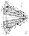
- An in Figures 3 . 4 and 5 shown objective lens 100 is used to focus an electron beam in a Elektronenmikroskopieanssen.
- the objective lens 100 comprises a magnetic lens as well as an electrostatic lens, thus the focusing is done both electrostatically and magnetically.
- the electrostatic lens also serves to decelerate the electrons of the primary electron beam.
- the magnetic lens comprises a pole piece arrangement with an inner pole piece 111 and an outer pole piece 112. Both pole pieces 111, 112 are a central optical axis 101, ie, the rotational direction of the beam path of a primary electron beam is rotationally symmetrical.
- the inner pole piece 111 has a substantially conical shape in the z direction and tapers continuously in this cone-shaped area in the direction of the object plane. In a lowermost region of the inner pole piece 111 in the z-direction, the latter has a hollow-cylindrical region 111 'extending in the z-direction over approximately 2.2 mm.
- the inner side 190 of the inner pole piece 111 extends from a lowermost position 192 in the z-direction first about 32 mm parallel to the axis 101 and then extends along a cone with an angle ⁇ of 10.5 ° to the z-axis, to this merges into a radial flange 111 '', which in its outer region is opposite a radial flange region 112 'of the outer pole shoe 112.
- the outer, further away from the axis 101 surface 191 of the inner pole piece 111 extends only in the hollow cylindrical Area 111 'about 2.2 mm parallel to the optical axis and then passes into a cone at an angle ⁇ of 16 ° to the z-axis until it merges into a Radialflanschteil 111 "of the inner pole piece 111.
- the outer pole piece 112 extends substantially conically in the z direction up to an upper flange area 112 '.
- An inner side 180 of the outer pole piece 112 in this conical region forms an angle ⁇ of 29 ° with respect to the axis 101, while an outer side 181 extends radially outward at an angle ⁇ of 34 ° to the axis 101.
- this has a central opening whose inner diameter is substantially equal to the inner diameter D i (see. FIG. 2 ) corresponds to the opening at the lowest point 192 in the inner pole piece 111 in the z-direction.
- a distance between the two pole pieces decreases in the direction of the object plane and reaches a smallest dimension in a lower region 111 'of the inner pole piece 111.
- an axial pole piece gap 119 running parallel to the z-direction and having a pole piece spacing is formed.
- the pole piece gap 119 in this embodiment has an axial length of about 6 mm.
- the arrangement and configuration of Polschuhspalts 119 is for the function of the magnetic lens of great importance.
- the pole pieces 111, 112 "somewhat" cling to the magnetic field.
- the field lines extend between the upper and the lower pole piece bulged in the direction of the optical axis 101 bulged shape.
- a maximum field strength on the optical axis 101 is in the region of the Polschuhspalts 119 reaches, wherein the field strength of the generated magnetic field substantially in the z-direction has a bell shape.
- a flat support ring 116 is disposed of non-magnetic material at the lowest end 192 of the inner pole piece 111 in Polschuhspalt 119, which has the same inner diameter as the hollow cylindrical portion 111 'of the inner pole piece 111, but a larger outer diameter.
- Polschuhspalt 119 a made of elastic material sealing ring 130 is further provided which abuts areas of the support ring 116, the outer pole piece 112 and a lower portion of insulation 118 'and a seal of the enclosed by the pole pieces 111, 112 space of the vacuum space in Area of an object to be examined and within the electron microscopy system.
- the Polschuhan extract is made of Permenorm ® 5000 H3, an iron-nickel alloy, by turning and subsequent annealing. A diagram of the field dependent flux density or magnetization of this material is in FIG. 6 played.
- a bobbin 115 is arranged in the inner space formed between the inner pole piece 111 and the outer pole piece 112.
- the bobbin 115 comprises coaxially with the optical axis arranged wire coils with a wire thickness of 0.8 mm and is made of copper. The number of turns is 650.
- the coils can be operated with a maximum current of 2A. A resulting in current flow through the coils heat output is in the range of about 20 watts.
- Between the coil turns is a Epoxy resin filled, which causes thermal and mechanical stability after curing.
- the bobbin 115 is substantially adapted in shape to the shape of the interior formed by the pole pieces 111, 112 without completely filling it.
- an upper side and an inner and an outer side of the bobbin 115 extend substantially parallel to the respective opposite surfaces of the pole piece assembly.
- the bobbin 115 is enclosed gap-free by a first jacket 120 and extends in a region of the outer side of the bobbin 115 extending parallel to the z-axis a second sheath 122 enclosed gap-free.
- the sheaths 120, 122 are made of copper and serve to absorb and dissipate heat that is generated in current passage in the wire coils of the bobbin 115.
- a gap 123 is left over the entirety of the area of the inner pole piece 111 opposite the first sheath 120 in order to provide thermal insulation and substantially prevent heating of the pole shoe material .
- an annular spacer 131 is inserted between a short vertical extension 120 'of the first shell 120 and the outer side 191 of the inner pole piece 111 to contact the pole piece 111 and the first shell 120 to prevent and provide the gap 123.
- the vertical extension of the first casing 120 is followed in the horizontal direction radially outward by a pipe 121 through which cooling water flows.
- a gap 124 for thermal insulation.
- the second sheath 122 has an essentially inverted L-shape and runs parallel to a parallel to the axis 101 portion of the outer side of the bobbin 115, while in the horizontal direction spatially connects to the first sheath 120 and a bore for receiving a screw 153, which is provided for connecting inner pole piece 111 and bobbin 115 with sheaths 120, 122 using a switching body 135. Between a head of the screw 153 and the second casing 122, a washer 132 is disposed.
- the flange portion 111 '' of the inner pole piece 111 and an opposite flange 112 'of the outer pole piece 112 have mutually aligned bores 154 and 155 for screwing the two pole pieces 111, 112 together.
- the outer pole piece 112 further has on its outer side 181 in the region of the transition from cone shape to the flange region 112 'on a step shape, which serves to fit the Polschuhan extract in a corresponding, manufactured for receiving part of the electron microscope.
- An insulation 118 made of plastic extends parallel to and along the inner side 190 of the inner pole piece 111 in a lower region beyond a lower end 192 of the inner pole piece 111 to about a lowest point 182 of the outer pole piece 112.
- In an upper area goes the insulation 118 parallel to the inner pole piece 111 in a flange portion 118 '' over, which extends approximately to the middle of the flange portion 111 '' of the inner pole piece 111.
- In an edge region of the flange portion 118 '' of the insulation 118 is a bore for receiving a the insulation 118 with the inner pole piece 111 connecting Screw 152 provided.
- annular recess for receiving a sealing ring 133 is provided in a side of the insulation 118 facing the inner pole piece 111.
- the insulation 118 In a conical portion of the inner side of the inner pole piece 111, the insulation 118 is spaced from the inner pole piece 111 leaving a gap.
- the insulation 118 assumes a hollow cylindrical shape 118 'in a lower region. In this hollow-cylindrical region 118 'of the insulation 118, this has an annular recess 117 which extends over almost the entire height of the hollow-cylindrical region and accommodates saddle-shaped deflection coils (not shown) for deflecting the electron beam.
- the jet pipe 113 forming a first electrode of the electrostatic lens is fitted.
- the jet pipe 113 extends in the z-direction beyond both an upper and a lower end of the hollow cylindrical portion 118 'of the insulation 118.
- the inner diameter of the jet pipe 113 is about 4.5 mm.
- a lower end of the beam tube 113 has a distance to the lowest point or the lower end 182 of the outer pole piece 112 of about 5 mm.
- the jet pipe 113 in this embodiment has an end flange 113 'having a rounded shape in axial cross-section and having a diameter of about 8.5 mm at its greatest radially outwardly extending extent.
- the end flange 113 ' extends from a pointing in the direction of the object plane front portion 113' in a rounded shape in a substantially parallel to the axis 101 disposed shell portion 113 ''', wherein the radius of curvature R F of this rounding is about 2 mm.
- the this bottom flange 113 'assigning the lowest part of the insulation 118 and the Shape of the end flange 113 'of the jet pipe 113 are adapted to each other so that their surfaces are arranged substantially parallel and so a gap 136 of semi-circular shape with uniform spacing around the end flange 113' is formed around.
- the end flange 113 ' serves to protect the plastic of the insulation 118 from electrons and charge caused by them.
- a recess for receiving a ring 134 is provided, which comes to bear on a side facing away from the insulation for abutment against a region of the outer pole piece.
- the electrostatic lens of the objective lens 100 has a termination electrode 114 as a second electrode.
- This termination electrode 114 is substantially conical in shape, with an angle between an outer side of the termination electrode 114 and the axis 101 being equal to the angle ⁇ between the outer side 181 of the outer pole piece 112 and the axis 101, with outer pole piece 112 and termination electrode 114 aligned with each other.
- the termination electrode 114 tapers in the z-direction to a central opening of about 5 mm inner diameter.
- the lower end of the jet tube 113 has a distance A 2 of about 5 mm to a lowermost point or the lower end of the terminating electrode 114 in the z-direction. While at the beam tube 113, a positive voltage of 8kV is applied, the termination electrode 114 is preferably connected to ground potential.
- the termination electrode 114 is made of Mumetall®, namely a material available from the vacuum melt Hanau, Germany, under the name Hyperm 766.
- the termination electrode 114 is held by two opposing clamps 150 secured to the outer pole piece 112 in an upper area with screws 151.
- the brackets 150 are disposed in their lower portion at an uppermost cone-shaped portion of the termination electrode 114.
- the termination electrode 114 is held and centered by the insulation 118 '.
- ceramic insulating material is used under the screw 151 connecting the outer pole piece 112 and the clamp 150. This arrangement or holder allows easy replacement of the termination electrode 114.
- the termination electrode 114 can be electrically isolated from the outer pole piece 112 to a potential other than ground potential.
- FIG. 4 In addition, an object to be examined 400 and a working distance W D between the lower end of Termination electrode 114 and a surface of the object 400 and the distances A 1 and A 2 shown.
- FIG. 8 An exemplary embodiment of the examination system for imaging and manipulating an object 400 is shown in a schematic, simplified form.
- the inspection system includes electron microscopy system 300 for imaging a portion of object 400 and ion beam processing system 200 for manipulating object 400.
- the optical axes of electron microscopy system 300 and ion beam processing system 200 intersect substantially in a plane defined by the planar surface of the object 400, the optical axis of the ion beam processing system 200 being approximately orthogonal to that plane and the ion beam correspondingly perpendicular to a surface of the object 400.
- the angle of incidence of the electron beam on the object 400 is approximately 35 ° in the figure, while the working distance, ie the distance between the surface of the object 400 and the lowermost, radially innermost point in the central opening of the termination electrode is approximately 4 mm.
- a primary electron beam is generated by an electron beam source comprising a cathode 301, preferably a Schottky field emitter, and an anode 303 opposite the cathode 301.
- the emitted electrons also pass through an extractor 302 located between the cathode 301 and the anode 303.
- the accelerated primary electron beam passes through a bore at the bottom of the anode 303 and is then collimated by a collimator assembly 304.
- the electron beam passes through an interior 306 of the electron microscopy system 300, in which a not shown Detector for detecting secondary electrons or backscattered electrons is arranged.
- the electron beam is focused by means of the magnetic lens formed from the pole piece arrangement with inner pole piece 309 and outer pole piece 308 and the coil body 307 arranged between them and the electrostatic lens 310, 311 which together form the objective lens.
- the objective lens saddle coils for deflecting the electron beam are also arranged symmetrically around the beam path.
- the electron beam emerges from the objective lens and strikes the object surface at an angle of approximately 35 ° at a working distance of approximately 4 mm.
- the objective lens has already been described in detail in the foregoing embodiment.
- Ion beam processing system 200 includes an ion source 201 comprising an array of liquid gallium drops disposed at a tip from which an ion beam is extracted by extraction electrode 202.
- an ion source 201 comprising an array of liquid gallium drops disposed at a tip from which an ion beam is extracted by extraction electrode 202.
- the ion optics of the FIB column 200 passes successively through a collimator 203, a variable orifice 204, a set of electrodes 205 and 206 for deflecting and aligning the ion beam, and finally an array of single-jet beamforming lenses 207, before the Ion beam emerges from the FIB column.
- the focused ion beam hits in FIG. 8 approximately at right angles to the object surface on the object, so that trenches or holes with vertical walls in the object surface can be generated under simultaneous observation by the electron microscope.
- FIG. 8 an object mount 401 for supporting and aligning the object 400 in front of an electron microscopy system 300 and ion beam processing system 200 indicated.
- a great advantage of the system according to the invention is to be able to observe and process an object at the same time. Mapping the object processing in situ is particularly important for determining the end point in the generation of particularly complex and / or small structures.
- simultaneous processing and imaging is made possible by the fact that the magnetic field of the magnetic lens of the objective lens of the electron beam microscope system is shielded by the objective lens that in the region of the object surface or the space penetrated by the ion beam, a magnetic field is so small that no or negligible small disturbing influence is exerted on the ion beam.
- This is particularly advantageous over so-called "single pole" lens lenses, whose space requirement can indeed be made quite small, but naturally generate a large magnetic field in the region of the object and can not be used simultaneously with a focused ion beam.
- the focused ion beam can also be directed by 2 ° in any direction deviating from the orthogon
Description
Die Erfindung betrifft ein Elektronenmikroskopiesystem mit magnetischer und elektrostatischer Fokussierung und insbesondere eine Objektivlinse für ein solches System. Ferner betrifft die Erfindung ein Untersuchungssystem zum Abbilden und Manipulieren eines Objektes, welches ein solches Elektronenmikroskopiesystem umfaßt.The invention relates to an electron microscopy system with magnetic and electrostatic focusing, and more particularly to an objective lens for such a system. Further, the invention relates to an inspection system for imaging and manipulating an object comprising such an electron microscopy system.
In einer Vielzahl von Fachbereichen und Anwendungsgebieten zeichnet sich ein zunehmender Trend zur Miniaturisierung ab. Insbesondere in der Halbleitertechnologie besteht Nachfrage an immer kleineren, komplexeren und leistungsstärkeren Bauelementen. Es besteht somit beispielsweise im Rahmen von Qualitätssicherung und Prozessanalyse ein Bedarf, die Wafer und darauf entstehende bzw. fertige Bauelemente optisch inspizieren zu können. Da die Größe der einzelnen Strukturen der Bauelemente im Mikrometerbereich und darunter liegt, werden üblicherweise Elektronenmikroskope verwendet, um eine notwendige Vergrößerung und Auflösung zu erzielen. Besonders vorteilhaft sind dabei solche Elektronenmikroskopiesysteme, welche eine Abbildung der zu untersuchenden Struktur unter einer großen Zahl von Beobachtungswinkeln zulassen, was bei zunehmender Wafergröße spezielle Anforderungen an die elektronenmikroskopische Anordnung stellt. Im Rahmen einer Charakterisierung einer Struktur, insbesondere einer Halbleiterstruktur, besteht eine Technik darin, einen Graben in die zu charakterisierende Struktur zu "fräsen", um einen Querschnitt durch die Struktur untersuchen zu können und so mit relativ geringem Arbeitsaufwand eine Fülle von Informationen, z.B. bezüglich Schichtenfolgen in der Struktur, erhalten zu können. Ein solcher Graben wird beispielsweise mit Hilfe eines fokussierten Ionenstrahls (focused ion beam, FIB) in die Halbleiterstruktur geätzt. Diese Ätzmethode ist besonders für die Herstellung von Probenquerschnitten für die Transmissionselektronenmikroskopie oder bei einer Struktur mit einer komplexen Schichtenfolge und unterschiedlicher Ätzselektivität der einzelne Schichten von Bedeutung. Verfahren unter Verwendung eines FIB erlauben die Herstellung recht feiner und wohldefinierter Schnitte. Es ist bei dieser Methode vorteilhaft, den Ätzvorgang in situ mikroskopisch beobachten können.A growing trend towards miniaturization is emerging in a variety of disciplines and applications. Especially in semiconductor technology there is a demand for ever smaller, more complex and more powerful components. For example, in the context of quality assurance and process analysis, there is a need to be able to visually inspect the wafers and components resulting therefrom or finished components. Since the size of the individual structures of the devices is in the micrometer range and below, electron microscopes are usually used to achieve necessary magnification and resolution. Particularly advantageous are those electron microscopy systems, which allow imaging of the structure to be examined under a large number of observation angles, which makes special demands on the electron microscopic arrangement with increasing wafer size. As part of a characterization of a structure, in particular a semiconductor structure, a technique is to "mill" a trench in the structure to be characterized in order to examine a cross section through the structure and so with relatively little Workload to be able to receive a wealth of information, eg regarding the sequence of layers in the structure. Such a trench is etched into the semiconductor structure, for example with the aid of a focused ion beam (FIB). This etching method is of particular importance for the production of sample cross-sections for transmission electron microscopy or in the case of a structure having a complex layer sequence and different etching selectivity of the individual layers. Methods using a FIB allow for the production of quite fine and well-defined cuts. It is advantageous in this method to observe the etching process in situ microscopically.
Aus dem Stand der Technik sind bereits verschiedene Elektronenmikroskopiesysteme sowie eine Zahl von in solchen Systemen anwendbaren Objektivlinsen bekannt. Eine solche Objektivlinse, die sich als vorteilhaft erwiesen hat, sieht eine Kombination aus magnetischer und elektrostatischer Fokussierung bzw. Verzögerung vor.Various electron microscopy systems as well as a number of objective lenses applicable in such systems are already known from the prior art. Such an objective lens, which has proved to be advantageous, provides a combination of magnetic and electrostatic focusing or delay.
Ein Beispiel einer herkömmlichen Objektivlinse ist in
Am Strahlrohr 13 der elektrostatischen Linse wird eine positive Spannung angelegt, während die Abschlußelektrode 14 vorzugsweise auf Erdpotential geschaltet ist. Die elektrostatische Linse erzeugt ein Verzögerungsfeld, in dem die Elektronen des Elektronenstrahls vor Verlassen der Elektronenoptik abgebremst werden. Dies erlaubt, daß die Elektronen des Elektronenstrahls den größten Teil des Strahlengangs zwischen Elektronenquelle und elektrostatischer Linse mit hoher Energie bzw. Geschwindigkeit durchlaufen können und so sich auf die Fokussierung negativ auswirkende elektrostatische Abstoßungserscheinungen der gleich geladenen Elektronen minimieren lassen. Das elektrostatische Feld zwischen Strahlrohrende und Abschlußelektrode 14 weist ferner eine Inhomogenität derart auf, daß dieses Feld ebenfalls fokussierend auf die dieses durchlaufende Primärelektronen wirkt.At the
Weiterhin hat sich als günstig erwiesen, daß ein durch die Magnetlinse der Objektivlinse erzeugtes Magnetfeld auf der Oberfläche eines Objekts - beispielsweise im Vergleich mit sog. "single-pole"-Linsen - relativ gering ist. Wie in
Eine Elektronenmikroskopieanordnung, welche eine solche Objektivlinse umfasst, wurde ebenfalls vorteilhaft in einer Anordnung zum Abbilden und Manipulieren eines Objekts, die zusätzlich eine Vorrichtung zum Erzeugen und Steuern eines fokussierten Ionenstrahls (im folgenden auch als Ionenstrahlbearbeitungssystem oder FIB-Säule bezeichnet) aufweist, eingesetzt. Insbesondere ermöglicht es eine solche Anordnung, Abbilden und Bearbeiten der Struktur simultan auszuführen. Aufgrund des Raumbedarfs der obig beschriebenen Objektivlinse der elektronenoptischen Anordnung sowie der FIB-Säule kann ein zu untersuchendes flächig ausgedehntes Objekt bei simultanem Abbilden und Bearbeiten maximal bis zu einem Winkel von 80° relativ zum Ionenstrahl angeordnet werden. Somit lassen sich in einem eine solche herkömmliche Objektivlinse umfassenden System mit Hilfe des FIB keine Gräben mit vertikalen Wänden in einem Objekt bei simultaner Abbildung durch das Elektronenmikroskop erzeugen. Vielmehr wird nach einem Arbeitsschritt zur Bearbeitung des Objekts durch den FIB das Objekt gekippt und verdreht, und anschließend die durch den FIB erzeugte Struktur abgebildet.An electron microscope device comprising such an objective lens has also been advantageously employed in an arrangement for imaging and manipulating an object additionally comprising an apparatus for generating and controlling a focused ion beam (hereinafter also referred to as an ion beam processing system or FIB pillar). In particular, such an arrangement enables mapping and editing of the structure to be carried out simultaneously. Due to the space requirement of the above-described objective lens of the electron-optical arrangement and the FIB column, a surface-extended object to be examined can be arranged with simultaneous imaging and processing at a maximum angle of 80 ° relative to the ion beam. Thus, in a system comprising such a conventional objective lens, with the aid of the FIB, vertical-wall trenches in an object can not be generated simultaneously with the electron microscope. Rather, after an operation to process the object by the FIB, the object is tilted and rotated, and then the structure produced by the FIB is mapped.
Bei gleichzeitigem Betreiben von Elektronenmikroskopieanordnung und fokussiertem Ionenstrahl ist allgemein ein Magnetfeld im Bereich des durch den Ionenstrahl manipulierten Objekts zu minimieren, da die Ionen durch das Magnetfeld abgelenkt werden, was zu einer Beeinträchtigung der Bearbeitungspräzision des fokussierten Ionenstrahls führt. Ferner kann in einem solchen Magnetfeld eine Aufspaltung des Ionenstrahls nach Isotopen auftreten, was eventuell dessen Verwendbarkeit ganz ausschließt.In general, when operating the electron microscope device and the focused ion beam, a magnetic field in the region of the object manipulated by the ion beam is to be minimized because the ions are deflected by the magnetic field, resulting in deterioration of the machining precision of the focused ion beam. Furthermore, in such a magnetic field, a splitting of the ion beam into isotopes may occur, which possibly completely precludes its usability.
Aus den Dokumenten
Es ist eine Aufgabe der vorliegenden Erfindung, eine Objektivlinse für ein Elektronenmikroskopiesystem vorzuschlagen, welches einen verringerten Raumbedarf und insbesondere einen verringerten Winkel zwischen einer optischen Achse der Objektivlinse und einem Außenrand des konischen äußeren Polschuhs aufweist.It is an object of the present invention to provide an objective lens for an electron microscopy system which has a reduced space requirement and in particular a reduced angle between an optical axis of the objective lens and an outer edge of the conical outer pole piece.
Diese Aufgabe wird gelöst durch eine Objektivlinse mit den Merkmalen des beigefügten Patentanspruchs 1. Vorteilhafte Ausgestaltungen dieser Objektivlinse sind in den beigefügten Patentansprüchen 2 bis 16 dargelegt. Ferner wird ein Untersuchungssystem mit den Merkmalen des Patentanspruchs 17 vorgeschlagen, welches diese Objektivlinse enthält.This object is achieved by an objective lens with the features of appended
Die Objektivlinse für ein Elektronenmikroskopiesystem mit magnetischer und elektrostatischer Fokussierung zum Abbilden eines in einer Objektebene anordenbaren Objektes umfasst:
- eine Polschuhanordnung zur Erzeugung eines fokussierenden Magnetfeldes, welche bezüglich einer sich in einer z-Richtung erstreckenden optischen Achse der Objektivlinse im wesentlichen rotationssymmetrisch ist und einen inneren Polschuh und einen äußeren Polschuh aufweist,
wobei an einer in z-Richtung untersten Stelle des inneren Polschuhs, wo dieser von dem äußeren Polschuh einen in z-Richtung orientierten Spaltabstand aufweist, zwischen dem inneren und dem äußeren Polschuh ein Polschuhspalt ausgebildet ist, - eine Elektrodenanordnung zur Erzeugung eines fokussierenden elektrostatischen Feldes, welche bezüglich der optischen Achse im wesentlichen rotationssymmetrisch ist, und umfasst: ein Strahlrohr, welches den inneren Polschuh entlang der optischen Achse durchsetzt und ein unteres Ende aufweist, und weiterhin eine mit Abstand von dem unteren Ende des Strahlrohrs angeordnete Abschlußelektrode,
- wobei für die Objektivlinse in einem Bereich innerhalb von wenigstens 3 cm um den Polschuhspalt herum gilt:
- der innere Polschuh verjüngt sich wenigstens bereichsweise (in z-Richtung) nach unten und weist dort einen inneren Konuswinkel β und einen äußeren Konuswinkel χ zur z-Richtung auf,
- der äußere Polschuh erstreckt sich nach unten, insbesondere verjüngt er sich hierbei wenigstens bereichsweise, und weist unten einen inneren Konuswinkel Δ und einen äußeren Konuswinkel α zur z-Richtung auf, und dadurch gekennzeichnet, daß weiterhin die Objektivlinse dazu ausgebildet ist, daß
- ein Arbeitsabstand WD zwischen der Abschlußelektrode und der Objektebene für Elektronen, die das Strahlrohr mit etwa 30 keV durchlaufen, kleiner als oder gleich 2 mm ist,
- 30° < α < 35° und 10° < Δ-χ < 14°.
- a pole piece arrangement for generating a focusing magnetic field which is substantially rotationally symmetrical with respect to an optical axis of the objective lens extending in a z-direction and has an inner pole piece and an outer pole piece,
wherein at a lowest point in the z-direction of the inner pole piece, where it has a z-direction-oriented gap distance from the outer pole piece, a pole shoe gap is formed between the inner and the outer pole piece, - an electrode arrangement for producing a focusing electrostatic field which is substantially rotationally symmetrical with respect to the optical axis, and comprising: a beam tube penetrating the inner pole piece along the optical axis and having a lower end, and further comprising a termination electrode spaced from the lower end of the beam tube,
- with the objective lens in a range within at least 3 cm around the pole shoe gap:
- the inner pole piece tapers at least in regions (in the z-direction) downwards and there has an inner cone angle β and an outer cone angle χ to the z-direction,
- the outer pole piece extends downwards, in particular it tapers at least regionally, and at the bottom has an inner cone angle Δ and an outer cone angle α with respect to the z direction, and characterized in that furthermore the objective lens is designed so that
- a working distance W D between the termination electrode and the object plane for electrons passing through the beam tube at about 30 keV is less than or equal to 2 mm,
- 30 ° <α <35 ° and 10 ° <Δ-χ <14 °.
Die Objektivlinse umfasst weiterhin einen in einem Raum zwischen dem inneren und dem äußeren Polschuh angeordneten Spulenkörper.The objective lens further comprises a bobbin disposed in a space between the inner and outer pole pieces.
Im Wesentlichen wurden Geometrie und Anordnung der Komponenten der herkömmlichen Objektivlinse verändert, um unter einem ersten Aspekt so den Winkel zwischen konischem äußeren Polschuh und z-Achse verringern zu können und damit den Raumbedarf der Objektivlinse und damit elektronenmikroskopischen Anordnung zu verringern. Dadurch kann ein im Wesentlichen flächig ausgedehntes Objekt bezüglich der optischen Achse der Elektronenmikroskopieanordnung stärker gekippt werden.In essence, the geometry and arrangement of the components of the conventional objective lens have been changed to accommodate a first aspect so as to be able to reduce the angle between the conical outer pole piece and the z-axis and thus to reduce the space requirement of the objective lens and thus electron microscopic arrangement. As a result, a substantially flat-extended object can be more tilted with respect to the optical axis of the electron microscope arrangement.
Die vorgeschlagene Änderung der Geometrie der herkömmlichen Objektivlinse, die zu einer die Aufgabe(n) lösenden Objektivlinse mit für das Elektronenmikroskopiesystem zufriedenstellenden optischen Parametern führt, ist dabei für den Fachmann nicht naheliegend, sondern aus einer Reihe von Gründen überraschend, wie nachfolgend dargestellt:
- In der magnetischen Linse der Objektivlinse sollen der innere und der äußere Polschuh den gesamten magnetischen Fluß führen, so daß das magnetische Feld im Wesentlichen nur für die kurze Strecke des Polschuhspalts aus diesen austritt. Weiterhin ist eine magnetische Sättigung des die Polschuhe ausbildenden Materials zu vermeiden, da eine solche Sättigung zu unreproduzierbaren und nicht rotationssymmetrischen Magnetfeldern und zu einer Verdrängung des Magnetflusses aus den Polschuhen heraus führen würde. Eine Fokussierung energiereicher Elektronenstrahlen würde im Falle einer Polschuhmaterialsättigung aufgrund des abgeschwächten Magnetfeldes beeinträchtigt. Daher würde eine Verringerung des Raumbedarfs der Magnetlinse durch eine Verringerung der Dicke der Polschuhe und damit Materialabtrag unter Beibehaltung der zur magnetischen Anregung durch die zwischen den Polschuhen angeordneten Spule verwendeten Parameter eine vorzeitige magnetische Sättigung des Materials und damit unzureichendes Fokussierungsvermögen der Objektivlinse erwarten lassen. Versuchte man, die Magnetlinse durch Verringerung des Abstandes, d.h. der Winkeldifferenz von innerem und des äußerem Polschuh zu verkleinern, würde diese Verringerung zu magnetischem Kurzschluß und damit zu nachteiligen Störungen des Magnetfeldes, insbesondere Verschiebungen, Verformungen und Abschwächungen des Feldes entlang der optischen Achse, führen. Außerdem würde dadurch der für die Spule zur Verfügung stehende Raum verkleinert, infolgedessen müßte zum Erhalt der zu einer genügenden Erregung notwendigen Anzahl der Windungen der Spule ein kleinerer Drahtdurchmesser für den für die Spule verwendeten Draht gewählt werden. Der mit einem kleineren Drahtdurchmesser verbundene höhere Ohm'sche Widerstand würde jedoch die von dem Draht der Spule erzeugte Wärmemenge erhöhen, was zur Vermeidung räumlicher Drifterscheinungen eine aufwendigere Kühlung als die verwendete Wasserkühlung erforderlich machen würde. Daher scheinen Materialabtrag an den Polschuhen und/oder eine Verringerung des Abstandes des inneren und äußeren Polschuhs keine geeignete Maßnahmen zur Lösung der Aufgabe zu sein.
- In the magnetic lens of the objective lens, the inner and outer pole pieces should guide the entire magnetic flux, so that the magnetic field emerges from them substantially only for the short distance of the pole piece gap. Furthermore, a magnetic saturation of the material forming the pole pieces material should be avoided, since such saturation would lead to unreproducible and non-rotationally symmetric magnetic fields and to a displacement of the magnetic flux out of the pole pieces out. Focusing high-energy electron beams would be impaired in the case of peat material saturation due to the weakened magnetic field. Therefore, reducing the space requirement of the magnetic lens by reducing the thickness of the pole pieces and thus removing material while maintaining the parameters used for magnetic excitation by the coil located between the pole pieces would be expected to cause premature magnetic saturation of the material and hence inadequate focusing power of the objective lens. It was attempted, the magnetic lens by reducing the distance, ie the angular difference of the inner and the outer pole piece to reduce this reduction would lead to magnetic short circuit and thus adverse disturbances of the magnetic field, in particular shifts, deformations and attenuation of the field along the optical axis. In addition, this would reduce the space available for the coil, as a result, a smaller wire diameter for the wire used for the coil should be selected to obtain the necessary number of turns of the coil to a sufficient excitation. However, the higher ohmic resistance associated with a smaller wire diameter would increase the amount of heat generated by the wire of the coil, which would require more expensive cooling than the water cooling used to avoid spatial drifting phenomena. Therefore, removal of material on the pole shoes and / or a reduction in the spacing of the inner and outer pole pieces do not appear to be suitable measures for achieving the object.
Zusammen mit einer Verringerung des Winkels α zwischen der Außenseite des äußeren Polschuhs und einer Verringerung der Dicken der Polschuhe wurde auch eine Anordnung der Polschuhe zueinander, insbesondere die Differenz des Winkels zwischen dem äußeren Winkel χ des inneren Polschuhs zur z-Achse und dem inneren Winkel Δ des äußeren Polschuhs zur z-Achse, und die Abmessung des Polschubspalts bzw. -abstands, in nicht durch den Stand der Technik nahegelegter Weise abgewandelt, um zu einer überraschend leistungsfähigen Objektivlinse zu gelangen:
- Zumindest in einem Bereich innerhalb von etwa 3cm um den Polschuhspalt liegt α erfindungsgemäß in einem
Bereich von 30°bis 35°, die Differenz Δ-χ ineinem Bereich von 10°bis 14°, wobei mit dieser Anordnung bei Verwendung von Elektronen, die das Strahlrohr mit etwa 30 keV durchlaufen, ein Arbeitsabstand zwischen der Abschlußelektrode und der Objektebene kleiner als oder gleich 2 mm erreicht wird.
- According to the invention, α lies in a range of 30 ° to 35 °, the difference Δ-χ in a range of 10 ° to 14 °, at least in a region within about 3 cm around the pole gap, with this arrangement when using electrons, the Run through the jet pipe at about 30 keV Working distance between the termination electrode and the object plane less than or equal to 2 mm is achieved.
Der Arbeitsabstand ist hier als Abstand zwischen einem untersten Bereich bzw. einem unteren Ende der Abschlusselektrode und der Objektebene bzw. einem in diese angeordneten Objekt zu verstehen, wobei bei diesem Arbeitsabstand bei bestimmungsgemäßem Gebrauch eine auflösungsbeste Abbildung erzielt werden kann bzw. eine Auflösung erzielt werden kann, die nicht wesentlich verschieden ist von der spezifizierten Auflösung beim bestimmungsgemäßen Gebrauch.The working distance is to be understood here as the distance between a lowermost region or a lower end of the terminating electrode and the object plane or an object arranged in the latter, whereby a resolution-best imaging can be achieved or a resolution can be achieved at this working distance when used as intended which is not significantly different from the specified resolution when used as intended.
Die Objektivlinse kann jedoch auch bei Verwendung größerer Arbeitsabstände vorteilhaft eingesetzt werden.However, the objective lens can be advantageously used even when using larger working distances.
Besonders bevorzugt ist eine Anordnung, in der α = 34° und Δ-χ = 13°.Particularly preferred is an arrangement in which α = 34 ° and Δ-χ = 13 °.
An einer in z-Richtung untersten Stelle des inneren Polschuhs weist dieser von dem äußeren Polschuh einen in z-Richtung orientierten Spaltabstand auf, wo zwischen dem inneren und dem äußeren Polschuh ein Polschuhspalt ausgebildet ist. Im Bereich des Polschuhspalts tritt das Magnetfeld in Richtung der optischen Achse aus. Die Abmessungen des Polschuhspalts haben Einfluß auf die Stärke wie auch die räumliche Ausdehnung des magnetischen Feldes auf der optische Achse und damit auf die Fokuslänge der Objektivlinse. Bei der Optimierung der Polschuhgeometrie sind die Eigenschaften der sphärischen und chromatischen Aberration gegenüber der Fokussierleistung, die durch die Feldabflachung aufgrund von Materialsättigung oder zu großer Spaltbreite verringert wird, abzuwägen. Es wird ein Polschuhspaltabstand von mindestens 3 mm gewählt. Bei der Angabe dieses Abstandes ist zu beachten, daß es sich hier gewissermaßen um einen effektiven Polschuhspaltabstand handelt. Das bedeutet, daß es möglich ist, durch Hinzufügen weiteren Materials in Form beispielsweise eines dünnen Fortsatzes oder dünner Filme oder Folien den Polschuhspalt bzw. Polschuhabstand zwar unter einem geometrischen, nicht jedoch unter einem funktionellen Aspekt zu verkleinern. Durch dieses hinzugefügte Material werden nämlich infolge magnetischer Sättigung im hinzugefügten Material das von der Magnetlinse erzeugte Magnetfeld und damit die von dem inneren und äußeren Polschuh ausgehenden magnetischen Feldlinien nicht wesentlich beeinflußt, oder das Material wird an einer Stelle hinzugefügt, an der sich ohnehin kaum noch Fluß im Polschuh befindet.At a lowest point in the z-direction of the inner pole piece, the latter has a gap distance oriented in the z-direction from the outer pole piece, where a pole shoe gap is formed between the inner and outer pole piece. In the area of the pole shoe gap, the magnetic field exits in the direction of the optical axis. The dimensions of the Polschuhspalts have an influence on the strength as well as the spatial extent of the magnetic field on the optical axis and thus on the focal length of the objective lens. When optimizing the pole piece geometry, the characteristics of spherical and chromatic aberration must be balanced against the focusing power that is reduced by the field flattening due to material saturation or too large a gap width. It is selected a Polschuhspaltabstand of at least 3 mm. When specifying this distance, it should be noted that this is effectively an effective Polschuhspaltabstand. That means, that it is possible, by adding additional material in the form of, for example, a thin extension or thin films or foils, to reduce the pole shoe gap or pole shoe spacing under a geometrical but not under a functional aspect. Because of this added material, the magnetic field generated by the magnetic lens, and thus the magnetic flux lines emanating from the inner and outer pole pieces, are not significantly affected by magnetic saturation in the added material, or the material is added at a point where there is hardly any flow at all located in the pole piece.
In einer vorteilhaften Ausgestaltung der Erfindung erweitern sich eine innere und eine äußere Seite des inneren Polschuhs von einem in z-Richtung untersten Punkt des inneren Polschuhs in einer konischen Form nach oben. In einer alternativen, bevorzugten Ausführungsform ist der innere Polschuh derart ausgebildet, daß er sich von seinem unteren Ende in Form eines Zylindermantels etwa 1 mm bis 3 mm in z-Richtung nach oben erstreckt, bevor er sich dann zumindest auf einer äußeren Seite konisch erweitert. Bevorzugt verjüngt sich der äußere Polschuh nach unten.In an advantageous embodiment of the invention, an inner and an outer side of the inner pole piece extend upward from a lowest point of the inner pole piece in the z-direction in a conical shape. In an alternative, preferred embodiment, the inner pole piece is designed such that it extends from its lower end in the form of a cylinder jacket about 1 mm to 3 mm in the z-direction upwards, before it widens conically at least on an outer side. Preferably, the outer pole piece tapers downwards.
Vorzugsweise weist der innere Polschuh zumindest an seinem unteren Ende einen Innendurchmesser von 6 mm bis 8 mm auf, wobei ein Innendurchmesser von 7,5 mm besonders bevorzugt ist.Preferably, the inner pole piece at least at its lower end an inner diameter of 6 mm to 8 mm, with an inner diameter of 7.5 mm is particularly preferred.
Die Abmessung des radial innersten, axial um die Achse angeordneten untersten Bereichs des äußeren Polschuhs liegt bevorzugt in einem Bereich von 0,5 mm bis 3 mm, die Abmessung des radial innersten, axial um die Achse angeordneten untersten Bereichs des inneren Polschuhs beträgt bevorzugt 10 mm und mehr.The dimension of the radially innermost axially lowermost portion of the outer pole piece located axially about the axis is preferably in a range of 0.5 mm to 3 mm, the dimension of the radially innermost axially axially disposed lowest portion of the inner pole piece is preferably 10 mm and more.
Damit wurde, entgegen den Erwartungen des Fachmanns, sowohl Material von den Polschuhen entfernt sowie eine Winkeldifferenz zwischen den Polschuhen verringert, wobei trotz größerem Spaltabstand ein Arbeitsabstand von 2 mm und kleiner erreicht wird.Thus, contrary to the expectations of the expert, both material removed from the pole pieces and an angular difference between the pole pieces is reduced, despite a larger gap distance, a working distance of 2 mm and smaller is achieved.
In besonders bevorzugten Ausführungsformen ist ein in z-Richtung unteres Ende der Abschlußelektrode von einem in z-Richtung untersten Bereich des äußeren Polschuhs in z-Richtung mit Abstand angeordnet.In particularly preferred embodiments, a lower end of the terminal electrode in the z-direction is spaced from a z-direction lowermost region of the outer pole piece in the z-direction.
Besonders bevorzugt ist das Strahlrohr derart angeordnet, daß es eine durch einen in z-Richtung untersten Bereich des äußeren Polschuhs gebildete Öffnung des äußeren Polschuhs zumindest durchsetzt. In besonders bevorzugten Ausführungsformen durchsetzt das Strahlrohr die Öffnung des äußeren Polschuhs und ist das untere Ende des Stahlrohrs derart angeordnet, daß es in z-Richtung von der Öffnung des äußeren Polschuhs mit Abstand angeordnet ist, d.h. parallel zur optischen Achse verlaufend aus der Polschuhanordnung, insbesondere der Öffnung des äußeren Polschuhs heraustritt. Besonders bevorzugt ist also das untere Ende des Strahlrohrs in z-Richtung zwischen der Öffnung des äußeren Polschuhs und dem unteren Ende der Abschlußelektrode angeordnet.Particularly preferably, the jet pipe is arranged such that it at least passes through an opening of the outer pole shoe formed by a region of the outer pole shoe that is the lowest in the z direction. In particularly preferred embodiments, the jet pipe passes through the opening of the outer pole piece and the lower end of the steel tube is arranged so that it is spaced in the z-direction from the opening of the outer pole piece, ie parallel to the optical axis extending from the pole piece, in particular the opening of the outer pole piece emerges. Thus, the lower end of the jet pipe in the z-direction is particularly preferred between the opening of the outer pole piece and the lower end of the termination electrode.
Gemäß Ausführungsformen der Erfindung zeichnet sich eine Objektivlinse, ergänzend zu der obig beschriebenen besonderen geometrischen Ausgestaltung der durch die Polschuhanordnung ausgebildeten Magnetlinse (einschließlich der bevorzugten Ausführungsformen), durch eine magnetische Kopplung des äußeren Polschuhs und der Abschlußelektrode aus. Diese magnetische Kopplung wird dadurch erreicht, daß der äußere Polschuh, welcher nach außen im wesentlichen durch eine Konusfläche mit einem Konuswinkel (α) zur z-Richtung begrenzt ist, und die Abschlußelektrode, welche nach außen im Wesentlichen durch eine Konusfläche mit einem Konuswinkel (α') zur z-Richtung begrenzt ist, zum Reduzieren des Magnetfelds auf dem in der Objektebene anordnenbaren Objekt im wesentlichen spaltfrei magnetisch miteinander gekoppelt sind. Diese magnetische Kopplung bewirkt eine bessere Abschirmung des Magnetfeldes zu Bereichen außerhalb der Objektivlinse hin, was besonders vorteilhaft ist in Fällen, wo das Magnetfeld mit dem Objekt bzw. einer Probe störend interferiert oder auch bei der gleichzeitigen Bearbeitung des untersuchten Objekts mit Hilfe eines fokussierten Ionenstrahls, da das Magnetfeld die Ionen ablenken und damit den Bearbeitungsvorgang stören würde.According to embodiments of the invention, an objective lens, in addition to the above-described particular geometric configuration of the magnetic lens formed by the pole piece assembly (including the preferred embodiments), is characterized by a magnetic coupling of the outer pole piece and the termination electrode. This magnetic coupling is achieved in that the outer pole piece, which is bounded outwardly substantially by a conical surface with a cone angle (α) to the z-direction, and the terminal electrode, which outwardly substantially by a conical surface with a cone angle (α ') is limited to the z-direction, are coupled to reduce the magnetic field on the object plane in the object object substantially gap-free magnetically with each other. This magnetic coupling causes a better shielding of the magnetic field to areas outside the objective lens, which is particularly advantageous in cases where the magnetic field interferes with the object or a sample or in the simultaneous processing of the examined object by means of a focused ion beam, because the magnetic field would distract the ions and thus interfere with the machining process.
Besonders bevorzugt ist die Objektivlinse auch unter diesem Aspekt dazu ausgebildet, daß ein Arbeitsabstand kleiner als 2 mm ist für Elektronen, die das Strahlrohr mit etwa 30 keV durchlaufen.Particularly preferably, the objective lens is also designed under this aspect so that a working distance is less than 2 mm for electrons that pass through the beam pipe at about 30 keV.
In einer besonders bevorzugten Ausführungsform wird die magnetische Kopplung zwischen Abschlußelektrode und äußerem Polschuh dadurch erreicht, daß ein Spalt zwischen der Abschlußelektrode und dem äußeren Polschuh kleiner als 0,6 mm und noch mehr bevorzugt kleiner als 0,2 mm ist. Ein solcher Spalt zwischen Abschlußelektrode und äußerem Polschuh wird vorteilhaft dadurch ausgebildet, daß sich ein Bereich der Abschlußelektrode und ein Bereich des äußeren Polschuhs flächig gegenüberliegen.In a particularly preferred embodiment, the magnetic coupling between the termination electrode and the outer pole piece is achieved in that a gap between the termination electrode and the outer pole piece is smaller than 0.6 mm and even more preferably less than 0.2 mm. Such a gap between the terminal electrode and the outer pole piece is advantageously formed in that a region of the terminal electrode and a region of the outer pole piece face each other in a planar manner.
Besonders bevorzugt liegen sich ein in z-Richtung oberster Bereich der Abschlusselektrode und der in z-Richtung unterste Bereich des äußeren Polschuhs flächig gegenüber, wobei bevorzugt die sich gegenüberliegenden Flächen parallel zur z-Richtung angeordnet sind, und weiter bevorzugt zumindest der dem äußeren Polschuh flächig gegenüberliegende Bereich der Abschlusselektrode innerhalb der durch den in z-Richtung untersten Bereich des äußeren Polschuhs gebildeten Öffnung angeordnet ist.Particularly preferably, an uppermost region of the terminal electrode in the z-direction and the region of the outer pole shoe which is the lowest in the z-direction lie flat, wherein preferably the opposing surfaces are arranged parallel to the z-direction, and more preferably at least that of the outer pole shoe opposite region of the terminal electrode is disposed within the opening formed by the z-direction in the lowest area of the outer pole piece opening.
Besonders bevorzugt wird die Abschlußelektrode durch eine sich von einem unteren Bereich des äußeren Polschuhs aus entlang der Innenseite des inneren Polschuhs erstreckenden Kunststoffisolierung sowie elektrisch isolierte Klammern gehalten. Dies ermöglicht es insbesondere, die Abschlußelektrode, welche durch einen Spalt elektrisch isoliert von dem äußeren Polschuh ist, auf ein anderes Potential als Erdpotential schalten zu können, was für verschiedene Anwendungen vorteilhaft ist. Weiterhin erlaubt dies, die Abschlußelektrode unabhängig vom äußeren Polschuh austauschen zu können.Particularly preferably, the terminating electrode is held by a plastic insulation extending from a lower region of the outer pole shoe along the inside of the inner pole shoe and electrically insulated clamps. This makes it possible in particular to be able to switch the termination electrode, which is electrically insulated from the outer pole piece by a gap, to a potential other than ground potential, which is advantageous for various applications. Furthermore, this allows to exchange the terminating electrode independently of the outer pole piece.
Weiter bevorzugt ist eine Anordnung von äußerem Polschuh und Abschlußelektrode, in der die sich zumindest teilweise im Wesentlichen konisch erstreckenden Außenseiten des äußeren Polschuhs und der Abschlußelektrode miteinander fluchten.Further preferred is an arrangement of outer pole piece and termination electrode, in which the at least partially substantially conically extending outer sides of the outer pole piece and the termination electrode are aligned with one another.
Die Abschlußelektrode ist vorteilhaft derart gestaltet, daß sie sich bis zu einer zentralen Öffnung am unteren Ende der Abschlußelektrode hin im Wesentlichen konisch verjüngt und so das elektrostatische Feld vergleichsweise nahe an einem Objekt bzw. einer Probe bereitgestellt wird. Da die Abschlußelektrode vorzugsweise auf Erdpotential geschaltet ist, ist in einem Bereich der Probe das elektrostatische Feld jedoch vernachlässigbar klein. Die Nähe des Feldes zur Probe ist insbesondere bei größeren Arbeitsabständen WD, d.h. Abständen zwischen Abschlußelektrode und Probenoberfläche, von Vorteil. Der Innendurchmesser der zentralen Öffnung der Abschlußelektrode entspricht im wesentlichen einem Innendurchmesser des Strahlrohrs, es sind aber auch Ausführungsformen vorgesehen, in denen die zentrale Öffnung am unteren Ende der Abschlußelektrode einen anderen Innendurchmesser aufweist als der Innendurchmesser des Strahlrohrs.The termination electrode is advantageously designed so that they are up to a central opening at the lower end of the End electrode tapers substantially conically and so the electrostatic field is provided comparatively close to an object or a sample. However, since the termination electrode is preferably connected to ground potential, the electrostatic field is negligibly small in a region of the sample. The proximity of the field to the sample is particularly advantageous for larger working distances W D , ie distances between the terminal electrode and the sample surface. The inner diameter of the central opening of the termination electrode substantially corresponds to an inner diameter of the jet pipe, but embodiments are also provided in which the central opening at the lower end of the termination electrode has a different inner diameter than the inner diameter of the jet pipe.
Gemäß weiteres Ausfuhrungsformen der Erfindung ist die elektrostatische Linse der Objektivlinse, ergänzend zu den obig beschriebenen besonderen geometrischen Parametern der Magnetlinse und/oder magnetischen Kopplung von äußerem Polschuh und Abschlusselektrode einschließlich der in Zusammenhang mit diesen beschriebenen bevorzugten Ausführungsformen, derart ausgestaltet, daß ein Abstand A1 zwischen dem unteren Ende des inneren Polschuhs und dem unteren Ende bzw. der in z-Richtung untersten Stelle des Strahlrohrs größer als 9 mm und weiter bevorzugt größer als 10 mm ist. Diese Ausgestaltung ist besonders bevorzugt zum Reduzieren des Magnetfeldes in der Objektebene vorgesehen. Besonders bevorzugt und besonders vorteilhaft ist bei dieser Ausgestaltung das untere Ende des Strahlrohrs in z-Richtung zwischen unterstem Bereich des äußeren Polschuhs und dem unteren Ende der Abschlusselektrode angeordnet. In einer besonders bevorzugten Ausführungsform ist ein Abstand A2 zwischen dem unteren Ende des Strahlrohrs und dem unteren Ende der Abschlußelektrode größer als 3 mm, besonders bevorzugt ist ein Abstand von etwa 6 mm.According to further embodiments of the invention, the electrostatic lens of the objective lens, in addition to the above-described special geometric parameters of the magnetic lens and / or magnetic coupling of outer pole piece and terminal electrode including the described in connection with these preferred embodiments, designed such that a distance A 1 between the lower end of the inner pole piece and the lower end and the lowest point in the z-direction of the jet pipe is greater than 9 mm and more preferably greater than 10 mm. This embodiment is particularly preferably provided for reducing the magnetic field in the object plane. Particularly preferred and particularly advantageous in this embodiment, the lower end of the jet pipe is arranged in the z-direction between the lowermost region of the outer pole piece and the lower end of the termination electrode. In a particularly preferred embodiment, a distance A 2 between the lower end of the jet pipe and the lower End of the termination electrode greater than 3 mm, more preferably a distance of about 6 mm.
Dieser Anordnung liegt die Idee zugrunde, eine Überlappung des durch die Magnetlinse erzeugten Magnetfeldes und des durch die Abschlußelektrode und Strahlrohr umfassende elektrostatische Linse erzeugten elektrostatischen Feldes gegenüber der aus dem Stand der Technik bekannten Anordnung zu verkleinern. Insbesondere überlappen das elektrostatische und das magnetische Feld bei einer solchen Linsengeometrie bevorzugt um weniger als 5% (bezogen auf die Feldintegrale). Damit weist das durch die magnetische Linse erzeugte Magnetfeld einen größeren Abstand zu einem abzubildenden Objekt auf, wodurch ein Magnetfeld in der Objektebene bzw. auf dem Objekt minimiert wird. Gründe, warum diese Feldminimierung auf dem Objekt vorteilhaft ist, wurden bereits zuvor angesprochen. Ein weiterer Vorteil dieser Anordnung liegt darin, daß das elektrostatische Feld nahe zur Probe angeordnet ist, was besonders bei größeren Arbeitsabständen vorteilhaft ist.This arrangement is based on the idea to reduce an overlap of the magnetic field generated by the magnetic lens and the electrostatic field generated by the terminal electrode and beam tube electrostatic field with respect to the known from the prior art arrangement. In particular, the electrostatic and magnetic fields in such a lens geometry preferably overlap by less than 5% (relative to the field integrals). Thus, the magnetic field generated by the magnetic lens at a greater distance to an object to be imaged, whereby a magnetic field in the object plane or on the object is minimized. Reasons why this field minimization on the object is advantageous have already been mentioned before. Another advantage of this arrangement is that the electrostatic field is located close to the sample, which is particularly advantageous for larger working distances.
Besonders bevorzugt weist das untere Ende des Strahlrohrs einen Endflansch auf, welcher sich radial über einen Außendurchmesser des Strahlrohrs hinaus erstreckt. Dabei weist der das Strahlrohr umschließende Endflansch einen Abstand zu der Abschlußelektrode auf, welcher groß genug ist, um ein Auftreten elektrischer Überschläge oder Kurzschlüsse zu verhindern. Dieser Endflansch ist vorzugsweise derart ausgebildet, daß er im Axialquerschnitt von einem in Richtung der Objektebene weisenden Frontabschnitt zu einem Mantelabschnitt in verrundeter Form übergeht, wobei diese Verrundung einen Krümmungsradius von mindestens einem Millimeter aufweist. Dieser besonderen Ausgestaltung des Strahlrohrs liegt die Idee zugrunde, im Bereich im Wesentlichen zwischen innerem Polschuh und Strahlrohr angeordnete, aus Kunststoff gefertigte Komponenten der Objektivlinse vor einer Aufladung durch eine beim Betreiben der Elektronenmikroskopieanordnung unausweichlich auftretenden Elektronenwolke zu schützen, indem gewissermaßen der direkte Zugang zu diesem Bereich durch die Abschirmung durch den Endflansch erschwert wird und der Primärelektronenstahl ähnlich wie durch einen Faraday'schen Käfig abgeschirmt wird. Der Endflansch kann auch derart ausgestaltet sein, daß ein Übergang von der den Innendurchmesser begrenzenden Innenwand des Strahlrohrs zur Frontfläche verrundet ausgebildet ist.Particularly preferably, the lower end of the jet pipe has an end flange which extends radially beyond an outer diameter of the jet pipe. In this case, the end flange enclosing the jet tube has a distance to the termination electrode, which is large enough to prevent the occurrence of electrical flashovers or short circuits. This end flange is preferably designed such that in the axial cross-section it merges from a front section pointing in the direction of the object plane to a jacket section in rounded form, this rounding having a radius of curvature of at least one millimeter. This particular embodiment of the jet pipe is based on the idea, in the area substantially between the inner pole piece and the jet pipe, made of plastic components of the objective lens before to protect a charge by an electron cloud inevitably occurring in the operation of the electron microscope assembly by, as it were, the direct access to this area is made difficult by the shielding by the end flange and the primary electron beam is shielded similar as by a Faraday cage. The end flange can also be designed such that a transition from the inner diameter bounding inner wall of the jet pipe is rounded to the front surface.
Bei allen obig angeführten Ausgestaltungen wird für die Polschuhe vorzugsweise ein Material gewählt, das eine hohe Sättigungsmagnetisierung aufweist. Besonders bevorzugt wird für die Polschuhe eine Eisen-Nickel-Legierung mit einem Nickel-Gehalt von 45% bis 50% verwendet. Besonders bevorzugt ist eine NiFe-Legierung mit dem Handelsnamen "Permenorm 5000 H3", kommerziell erhältlich von der Vacuumschmelze Hanau, Deutschland. Vorteilhaft können auch eine Cobalt-Eisen-Vanadium-(49%Co-49%Fe-2%V)-Legierung, Cobalt-Eisen-Legierungen (z.B. 30% Co, 70% Fe) oder Weicheisen verwendet werden.In all the above-mentioned embodiments, a material is preferably selected for the pole shoes, which has a high saturation magnetization. Particularly preferred for the pole pieces, an iron-nickel alloy is used with a nickel content of 45% to 50%. Particularly preferred is a NiFe alloy with the trade name "
Das für den Spulenkörper verwendete Material umfasst vorzugsweise Kupferdraht. Der Spulenkörper ist thermisch von den Polschuhen isoliert, wobei bei Stromdurchfluß in dem Spulenkörper generierte Wärme von einem thermisch mit dem Spulenkörper gekoppelten, im Innenraum zwischen dem innern und dem äußeren Polschuh angeordneten Wasserkühlungsrohr aufgenommen und durch den Kühlkreislauf abtransportiert wird.The material used for the bobbin preferably comprises copper wire. The bobbin is thermally insulated from the pole pieces, heat generated in the bobbin when current flows through a thermally coupled to the bobbin, received in the interior space between the inner and outer pole piece water cooling pipe and transported away through the cooling circuit.
Für die Abschlußelektrode wird bevorzugt ein sogenanntens µMetall (Mumetall®), d.h. eine Nickel-Eisen-Legierung mit einem Nickel-Anteil von 72 - 89%, gewählt, besonders bevorzugt Hyperm 766.A so-called μ metal (Mumetall®), ie a nickel-iron alloy with a nickel content of 72-89%, is preferably selected for the termination electrode, particularly preferably Hyperm 766.
Bevorzugt sind in der Objektivlinse weiterhin mehrere Ablenkspulen zum Ablenken des Elektronenstrahls vorgesehen, so daß der Elektronenstrahl über einen definierten Bereich einer Objektoberfläche rastern kann. Neben der voranstehend beschriebenen Objektivlinse umfasst ein Elektronenmikroskopiesystem weitere Komponenten: eine Probenkammer, in der ein zu untersuchendes Objekt angeordnet ist, eine Elektronenstrahlquelle zum Erzeugen und Beschleunigen eines Elektronenstrahls, Elektronenoptik mit einer oder mehreren elektrostatischen und/oder magnetischen Linse(n), zumindest ein Vakuumsystem zum Evakuieren zumindest der vom Elektronenstrahl durchsetzten Räume des Elektronenmikroskops und der Probenkammer, eine Objekthalterung in der Probenkammer zum Anordnen und Ausrichten eines Objekts vor dem Elektronenmikroskop und zumindest einen Detektor zum Detektieren von Elektronen, insbesondere Sekundärelektronen. In einer bevorzugten Elektronenmikroskopieanordnung ist zumindest ein Detektor in einem Innenraum des Elektronenmikroskops, welcher in z-Richtung oberhalb der Objektivlinse angeordnet ist, vorgesehen.Preferably, a plurality of deflection coils for deflecting the electron beam are further provided in the objective lens, so that the electron beam can scan over a defined area of an object surface. In addition to the objective lens described above, an electron microscopy system comprises further components: a sample chamber in which an object to be examined is arranged, an electron beam source for generating and accelerating an electron beam, electron optics with one or more electrostatic and / or magnetic lens (s), at least one vacuum system for evacuating at least the electron beam traversed by the electron beam and the sample chamber, an object holder in the sample chamber for arranging and aligning an object in front of the electron microscope and at least one detector for detecting electrons, in particular secondary electrons. In a preferred electron microscope arrangement, at least one detector is provided in an inner space of the electron microscope, which is arranged in the z-direction above the objective lens.
Unter einem zusätzlichen Aspekt stellt die Erfindung ein Untersuchungssystem zur Beobachtung und zur Manipulation eines zu untersuchenden Objekts bereit, welches folgende Komponenten umfaßt:
- ein Elektronenmikroskopiesystem mit einer Objektivlinse gemäß obiger Beschreibung,
- ein Ionenstrahlbearbeitungssystem zum Manipulieren des Objekts mittels eines emittierten Ionenstrahls,
- eine Objekthalterung zur Halterung und Ausrichtung des Objekts vor dem Ionenstrahlbearbeitungssystem und dem Elektronenmikroskopiesystem, mit der ein flächig ausgedehntes Objekt derart vor dem Elektronenmikroskopiesystem ausrichtbar ist, daß der Ionenstrahl die Objektoberfläche orthogonal schneidet.
- an electron microscopy system with an objective lens as described above,
- an ion beam processing system for manipulating the object by means of an emitted ion beam,
- an object holder for holding and aligning the object in front of the ion beam processing system and the Electron microscopy system, with an area-wide object can be aligned in front of the electron microscope system so that the ion beam orthogonally intersects the object surface.
Große Vorteile ergeben sich aus einer Kombination des voranstehend beschriebenen Elektronenmikroskopiesystems mit einem Ionenstrahlbearbeitungssystem. Das Ionenstrahlbearbeitungssystem ist zur Erzeugung und Lenkung eines fokussierten Ionenstrahls vorgesehen, mit Hilfe dessen ein zu untersuchendes Objekt beispielsweise durch Abtragen von Material aus einem definierten Bereich der Oberfläche des Objekts manipuliert wird. Neben der Möglichkeit zur Untersuchung von Objekten z.B. in Hinblick auf deren Topographie besteht auch die Möglichkeit, Reparaturarbeiten an lithographischen Masken oder direktschreibende Lithographieverfahren unter Verwendung dieser Anordnung auszuführen. Es sind darüber hinaus weitere Anwendungsmöglichkeiten denkbar. Das Ionenstrahlbearbeitungssystem umfaßt zum Erzeugen eines Ionenstrahls eine Ionenquelle, für die häufig eine Flüssigmetall-Ionenquelle (häufig Gallium oder Indium) verwendet wird sowie eine Extraktionselektrode zum Extrahieren von Ionen aus der Ionenquelle durch Anlegen eines elektrostatischen Feldes. Weiterhin umfaßt eine Ionenoptik des Ionenstrahlbearbeitungsystems zum Beschleunigen, Fokussieren und Führen bzw. Ablenken des Ionenstrahls zumindest eine Beschleunigungselektrode, elektrostatische Linsen, eine variable Apertur und Ablenkeinheiten.Great advantages result from a combination of the above-described electron microscopy system with an ion beam processing system. The ion beam processing system is provided for generating and directing a focused ion beam, by means of which an object to be examined is manipulated, for example, by removing material from a defined area of the surface of the object. Besides the possibility to examine objects e.g. in view of their topography, it is also possible to carry out repair work on lithographic masks or direct-writing lithography processes using this arrangement. There are also other applications conceivable. The ion beam processing system includes an ion source for generating an ion beam, often using a liquid metal ion source (often gallium or indium) and an extraction electrode for extracting ions from the ion source by applying an electrostatic field. Furthermore, ion optics of the ion beam processing system for accelerating, focusing, and deflecting the ion beam include at least one accelerating electrode, electrostatic lenses, variable aperture, and deflecting units.
Das Elektronenmikroskopiesystem und das Ionenstrahlbearbeitungssystem sind derart zueinander angeordnet, daß sich ihre optischen Achsen im Wesentlichen in einer durch eine Oberfläche des zu untersuchenden Objekts definierten Ebene schneiden. Das Objekt wird von einer Objekthalterung gehalten, die eine definierte Ausrichtung des Objekts vor Elektronenmikroskopiesystem und Ionenstrahlbearbeitungssystem erlaubt. So läßt sich der Winkel, unter dem der fokussierte Ionenstrahl und der fokussierte Elektronenstrahl auf der Objektoberfläche auftreffen, in einem definierten Winkelbereich einstellen. Dies erlaubt beispielsweise das Erzeugen von Löchern und Gräben mit unterschiedlich steilen Seitenwänden. Insbesondere läßt sich der Ionenstrahl senkrecht zum Objekt anordnen und ermöglicht daher das Erzeugen von Gräben mit senkrechten Seitenwänden, welchen für bestimmte Anwendungsbereiche eine große Bedeutung zukommen.The electron microscopy system and the ion beam processing system are arranged to each other such that their optical axes intersect substantially in a plane defined by a surface of the object to be examined. The object is held by an object holder which has a defined orientation of the object in front of the electron microscopy system and the ion beam processing system allowed. Thus, the angle at which the focused ion beam and the focused electron beam impinge on the object surface can be set in a defined angular range. This allows, for example, the creation of holes and trenches with differently steep side walls. In particular, the ion beam can be arranged perpendicular to the object and therefore enables the creation of trenches with vertical side walls, which are of great importance for certain fields of application.
Nachfolgend werden Ausführungsbeispiele der Erfindung anhand von Figuren näher erläutert. Hierbei zeigt
Figur 1- eine Querschnittsansicht durch einen unteren Teil einer herkömmlichen Objektivlinse für ein Elektronenmikroskopiesystem,
Figur 2- eine Illustration der in der Beschreibung definierten Winkel und Abmessungen im Bereich eines Polschuhspalts der Objektivlinse,
- Figur 3
- eine Querschnittsansicht durch ein Ausführungsbeispiel der erfindungsgemäßen Objektivlinse,
- Figur 4
- einen vergrößerten Ausschnitt aus
Figur 3 , Figur 5- einen vergrößerten Ausschnitt aus
Figur 3 bzw. 4, - Figur 6
- ein Diagramm der für ein Polschuhmaterial eines Ausführungsbeispiels der erfindungsgemäßen Objektivlinse charakteristischen Parameter Feldstärke und Flußdichte,
- Figur 7
- ein Diagramm der Überlagerung eines elektrostatischen und magnetischen Felds in einem Ausführungsbeispiel der erfindungsgemäßen Objektivlinse, und
- Figur 8
- eine schematische Darstellung eines erfindungsgemäßen Untersuchungssystems zum Abbilden und Manipulieren eines Objekts.
- FIG. 1
- a cross-sectional view through a lower part of a conventional objective lens for an electron microscopy system,
- FIG. 2
- an illustration of the angle and dimensions defined in the description in the region of a Polschuhspalts the objective lens,
- FIG. 3
- a cross-sectional view through an embodiment of the objective lens according to the invention,
- FIG. 4
- an enlarged section
FIG. 3 . - FIG. 5
- an enlarged section
FIG. 3 or 4, - FIG. 6
- a diagram of the characteristic of a pole piece material of an embodiment of the objective lens according to the invention parameters field strength and flux density,
- FIG. 7
- a diagram of the superposition of an electrostatic and magnetic field in one Embodiment of the objective lens according to the invention, and
- FIG. 8
- a schematic representation of an examination system according to the invention for imaging and manipulating an object.
Eine in
Der innere Polschuh 111 weist in z-Richtung im Wesentlichen eine konische Form auf und verjüngt sich in diesem konusförmigen Bereich kontinuierlich in Richtung zur Objektebene hin. In einem in z-Richtung untersten Bereich des inneren Polschuhs 111 weist dieser einen sich in z-Richtung über etwa 2,2 mm erstreckenden hohlzylinderförmigen Bereich 111' auf. Die innere Seite 190 des inneren Polschuhs 111 verläuft von einer in z-Richtung untersten Stelle 192 zunächst über etwa 32 mm hinweg parallel zur Achse 101 und erstreckt sich dann entlang einem Konus mit einem Winkel β von 10,5° zur z-Achse, bis dieser in einen Radialflansch 111'' übergeht, der in seinem äußeren Bereich einem Radialflanschbereich 112' des äußeren Polschuhs 112 gegenüberliegt. Die äußere, von der Achse 101 weiter entfernte Fläche 191 des inneren Polschuhs 111 verläuft lediglich in dem hohlzylinderförmigen Bereich 111' etwa über 2,2 mm parallel zur optischen Achse und geht dann in einen Konus mit einem Winkel χ von 16° zur z-Achse über, bis dieser in einen Radialflanschteil 111" des inneren Polschuhs 111 übergeht.The
Der äußere Polschuh 112 erstreckt sich bis zu einem oberen Flanschbereich 112' im Wesentlichen konisch in z-Richtung. Dabei bildet eine innere Seite 180 des äußeren Polschuhs 112 in diesem konischen Bereich einen Winkeln Δ von 29° zur Achse 101 aus, während eine äußere Seite 181 sich unter einem Winkel α von 34° zur Achse 101 nach radial außen erstreckt. An einer untersten Stelle 182 des äußeren Polschuhs 112 weist dieser eine zentrale Öffnung auf, deren Innendurchmesser im Wesentlichen gleich dem Innendurchmesser Di (vgl.
Aufgrund der unterschiedlichen Konusöffnungswinkel des inneren und des äußeren Polschuhs (111, 112) nimmt ein Abstand der beiden Polschuhe in Richtung zur Objektebene hin ab und erreicht in einem unteren Bereich 111' des inneren Polschuhs 111 eine kleinste Dimension. Zwischen der untersten Stelle 192 des inneren Polschuhs 111 und der untersten Stelle 182 des äußeren Polschuhs 112 wird ein parallel zur z-Richtung verlaufender, axialer Polschuhspalt 119 mit einem Polschuhabstand ausgebildet. Der Polschuhspalt 119 hat in dieser Ausführungsform eine axiale Länge von etwa 6 mm.Due to the different cone opening angles of the inner and outer pole piece (111, 112), a distance between the two pole pieces decreases in the direction of the object plane and reaches a smallest dimension in a lower region 111 'of the
Die Anordnung und Ausgestaltung des Polschuhspalts 119 ist für die Funktion der Magnetlinse von großer Bedeutung. Die Polschuhe 111, 112 "klammern" in gewisser Weise das magnetische Feld. Die Feldlinien verlaufen zwischen dem oberen und dem unteren Polschuh in bauchig in Richtung optischer Achse 101 ausgewölbter Form. Eine maximale Feldstärke auf der optischen Achse 101 wird im Bereich des Polschuhspalts 119 erreicht, wobei die Feldstärke des erzeugten magnetischen Feldes im Wesentlichen in z-Richtung eine Glockenform aufweist.The arrangement and configuration of
In der in
Im Polschuhspalt 119 ist weiterhin ein aus elastischem Material gefertigter Dichtungsring 130 vorgesehen, der an Bereichen des Stützrings 116, des äußeren Polschuh 112 und einem unteren Bereich einer Isolierung 118' anliegt und eine Dichtung des durch die Polschuhe 111, 112 eingeschlossenen Raumes von dem Vakuumraum im Bereich eines zu untersuchenden Objekts und innerhalb des Elektronenmikroskopiesystems bereitstellt.In Polschuhspalt 119 a made of elastic
Die Polschuhanordnung ist aus Permenorm® 5000 H3, einer Eisen-Nickel-Legierung, durch Drehen und anschließendes Ausglühen gefertigt. Ein Diagramm der vom Feld abhängigen Flußdichte bzw. Magnetisierung dieses Materials ist in
In dem zwischen dem inneren Polschuh 111 und dem äußeren Polschuh 112 gebildeten Innenraum ist ein Spulenkörper 115 angeordnet. Der Spulenkörper 115 umfaßt koaxial zur optischen Achse angeordnete Drahtspulen mit einer Drahtdicke von 0,8 mm und ist aus Kupfer gefertigt. Die Zahl der Windungen beträgt 650. Die Spulen können bei einer Stromstärke von maximal 2A betrieben werden. Eine bei Stromdurchfluß durch die Spulen entstehende Wärmeleistung liegt im Bereich von etwa 20 Watt. Zwischen die Spulenwindungen ist ein Epoxy-Harz eingefüllt, das nach Aushärten thermische und mechanische Stabilität hervorruft.In the inner space formed between the
Der Spulenkörper 115 ist in seiner Form im Wesentlichen der Form des durch die Polschuhe 111, 112 gebildeten Innenraums angepaßt, ohne diesen völlig auszufüllen. So erstrecken sich eine obere Seite und eine innere und eine äußere Seite des Spulenkörpers 115 im Wesentlichen parallel zu den jeweiligen, gegenüberliegenden Flächen der Polschuhanordnung. Zur äußeren Seite 191 des inneren Polschuhs 111, im Wesentlichen zur oberen Seite hin und zu einer unteren Seite hin wird der Spulenkörper 115 durch eine erste Ummantelung 120 spaltfrei eingeschlossen und in einem sich parallel zur z-Achse erstreckenden Bereich der äußeren Seite des Spulenkörpers 115 durch eine zweite Ummantelung 122 spaltfrei umschlossen. Die Ummantelungen 120, 122 sind aus Kupfer gefertigt und dienen der Aufnahme und Ableitung von Wärme, die bei Stromdurchlauf in den Drahtspulen des Spulenkörpers 115 erzeugt wird.The
Zwischen der ersten Ummantelung 120 und der äußeren Seite 191 des inneren Polschuhs 111 ist ein sich über die Gesamtheit des der ersten Ummantelung 120 gegenüberliegenden Bereich des inneren Polschuhs 111 ein Spalt 123 belassen, um eine thermische Isolierung bereitzustellen und eine Erwärmung des Polschuhmaterials im Wesentlichen zu verhindern. In einem in z-Richtung obersten Bereich des inneren Polschuhs 111 ist ein ringförmiger Abstandhalter 131 zwischen einem kurzen, vertikalen Fortsatz 120' der ersten Ummantelung 120 und der äußeren Seite 191 des inneren Polschuhs 111 eingesetzt, um eine Berührung von Polschuh 111 und erster Ummantelung 120 zu verhindern und den Spalt 123 bereitzustellen. An den vertikalen Fortsatz der ersten Ummantelung 120 schließt sich in horizontaler Richtung nach radial außen ein von Kühlwasser durchflossenes Rohr 121 an. Zwischen äußerem Polschuh 112 und Spulenkörper 115 ist zur thermischen Isolierung ein Spalt 124 belassen.Between the
Die zweite Ummantelung 122 weist im Wesentlichen eine invertierte L-Form auf und verläuft parallel zu einem zur Achse 101 parallelen Abschnitt der äußeren Seite des Spulenkörpers 115, während sie sich in horizontaler Richtung räumlich an die erste Ummantelung 120 anschließt und eine Bohrung zur Aufnahme einer Schraube 153 aufweist, die zum Verbinden von innerem Polschuh 111 und Spulenkörper 115 mit Ummantelungen 120, 122 unter Verwendung eines Vermittlungskörpers 135 vorgesehen ist. Zwischen einem Kopf der Schraube 153 und der zweiten Ummantelung 122 ist eine Unterlagscheibe 132 angeordnet. Der Flanschbereich 111'' des inneren Polschuhs 111 sowie ein diesem gegenüberliegender Flanschbereich 112' des äußeren Polschuhs 112 weisen miteinander fluchtende Bohrungen 154 und 155 zum Verschrauben der beiden Polschuhe 111, 112 miteinander auf. Der äußere Polschuh 112 weist darüber hinaus an seiner äußeren Seite 181 im Bereich des Übergangs von Konusform zum Flanschbereich 112' eine Stufenform auf, die der Einpassung der Polschuhanordnung in ein entsprechendes, zur Aufnahme gefertigtes Teil der Elektronenmikroskopieanordnung dient.The
Eine Isolierung 118 aus Kunststoff erstreckt sich parallel zu und entlang der inneren Seite 190 des inneren Polschuhs 111 in einem unteren Bereich über ein unterstes Ende 192 des inneren Polschuhs 111 hinaus bis etwa zu einer untersten Stelle 182 des äußeren Polschuhs 112. In einem oberen Bereich geht die Isolierung 118 parallel zum inneren Polschuh 111 in einen Flanschbereich 118'' über, der etwa bis zur Mitte des Flanschbereichs 111'' des inneren Polschuhs 111 reicht. In einem Randbereich des Flanschteils 118'' der Isolierung 118 ist eine Bohrung zur Aufnahme einer die Isolierung 118 mit dem inneren Polschuh 111 verbindenden Schraube 152 vorgesehen. Ebenfalls in einem Flanschbereich 118'' der Isolierung 118 ist in einer dem inneren Polschuh 111 zugewandten Seite der Isolierung 118 eine ringförmige Aussparung zur Aufnahme eines Dichtungsrings 133 vorgesehen. In einem konusförmigen Bereich der inneren Seite des inneren Polschuhs 111 ist die Isolierung 118 vom inneren Polschuh 111 unter Belassung eines Spalts beabstandet. Ebenso wie der innere Polschuh 111 nimmt die Isolierung 118 in einem unteren Bereich eine Hohlzylinderform 118' an. In diesem hohlzylinderförmigen Bereich 118' der Isolierung 118 weist diese eine ringförmige, sich fast über die gesamte Höhe des hohlzylinderförmigen Bereichs erstreckende Aussparung 117 auf, die nicht dargestellte sattelförmige Ablenkspulen zum Ablenken des Elektronenstrahls aufnimmt.An
In den Innenradius des hohlzylinderförmigen Bereichs 118' der Isolierung 118 ist das eine erste Elektrode der elektrostatischen Linse ausbildende Strahlrohr 113 eingepasst. Das Strahlrohr 113 erstreckt sich in z-Richtung sowohl über ein oberes wie auch eine unteres Ende des Hohlzylinderbereichs 118' der Isolierung 118 hinaus. Der Innendurchmesser des Strahlrohrs 113 beträgt etwa 4,5 mm. Ein unteres bzw. unterstes Ende des Strahlrohrs 113 weist einen Abstand zur untersten Stelle bzw. dem unteren Ende 182 des äußeren Polschuhs 112 von etwa 5 mm auf. Wie insbesondere aus
Des weiteren weist die elektrostatische Linse der Objektivlinse 100 eine Abschlußelektrode 114 als eine zweite Elektrode auf. Diese Abschlußelektrode 114 ist im Wesentlichen von konischer Form, wobei ein Winkel zwischen einer äußeren Seite der Abschlußelektrode 114 und der Achse 101 gleich dem Winkel α zwischen der äußeren Seite 181 des äußeren Polschuhs 112 und der Achse 101 ist, wobei äußerer Polschuh 112 und Abschlußelektrode 114 miteinander fluchten. Die Abschlußelektrode 114 verjüngt sich in z-Richtung bis hin zu einer zentralen Öffnung von etwa 5 mm Innendurchmesser. An einem oberen Ende der Abschlußelektrode 114 geht diese in einen ring- bzw. hohlzylinderförmigen Bereich 114' über, wobei eine Außenfläche dieses Ringbereichs 114' einer axialen Innenfläche des äußeren Polschuhs 112 flächig gegenüberliegt und der zwischen diesen ausgebildete, etwa 150 µm breite Spalt schmal genug ist, um eine magnetische Kopplung von Abschlußelektrode 114 und äußerem Polschuh 112 zu ermöglichen, wodurch eine noch bessere Abschirmung des Magnetfeldes in der Objektivlinse 100 von einem Bereich außerhalb der Objektivlinse 100 erreicht wird.Furthermore, the electrostatic lens of the
Das untere Ende des Strahlrohrs 113 weist in z-Richtung einen Abstand A2 von etwa 5 mm zu einer untersten Stelle bzw. dem unteren Ende der Abschlußelektrode 114 auf. Während am Strahlrohr 113 eine positive Spannung von 8kV anliegt, ist die Abschlußelektrode 114 vorzugsweise auf Erdpotential geschaltet. Durch die Wahl dieser gegenüber dem Stand der Technik größeren Abstände der Elektroden 113, 114 der elektrostatischen Linse voneinander und von der Polschuhanordnung wird das elektrostatische Verzögerungs- und Fokussierungsfeld von dem durch die Polschuhanordnung erzeugten Magnetfeld weitgehend separiert, die Felder der beiden Linsen überlappen in einem Bereich von weniger als 5% ihrer Feldintegrale, wie aus dem Diagramm in
Die Abschlußelektrode 114 ist aus Mumetall®, nämlich einem von der Vakuumschmelze Hanau, Deutschland, unter dem Namen Hyperm 766 erhältlichen Material gefertigt.The
Die Abschlußelektrode 114 wird durch zwei gegenüberliegende, in einem oberen Bereich mit Schrauben 151 am äußeren Polschuh 112 befestigte Klammern 150 gehalten. Die Klammern 150 sind in ihrem unteren Bereich an einem obersten konusförmigen Abschnitt der Abschlußelektrode 114 angeordnet. Die Abschlußelektrode 114 wird durch die Isolierung 118' gehalten und zentriert. Zur elektrischen Isolation der Klammern 150 vom äußeren Polschuh 112 wird keramisches Isolierungsmaterial unter der äußeren Polschuh 112 und Klammer 150 verbindenden Schraube 151 verwendet. Diese Anordnung bzw. Halterung ermöglicht ein leichtes Auswechseln der Abschlußelektrode 114. Zudem kann die Abschlußelektrode 114 elektrisch isoliert von dem äußeren Polschuh 112 auf ein anderes Potential als Erdpotential geschaltet werden.The
In
In
Wie aus
Im Elektronenmikroskopiesystem 300 wird ein Primärelektronenstrahl durch eine Elektronenstrahlquelle erzeugt, welche eine Kathode 301, vorzugsweise einen Schottky-Feldemitter, und eine der Kathode 301, gegenüberliegende Anode 303 umfaßt. Die emittierten Elektronen durchlaufen zudem einen zwischen Kathode 301 und Anode 303 angeordneten Extraktor 302. Der beschleunigte Primärelektronenstrahl tritt durch eine Bohrung am Boden der Anode 303 hindurch und wird anschließend von einer Kollimatoranordnung 304 kollimiert. Der Elektronenstrahl durchläuft nach einer Aperturblende 305 einen Innenraum 306 des Elektronenmikroskopiesystems 300, in dem ein nicht dargestellter Detektor zum Nachweis von Sekundärelektronen oder Rückstreuelektronen angeordnet ist. Mittels der aus der Polschuhanordnung mit innerem Polschuh 309 und äußerem Polschuh 308 sowie dem zwischen diesen angeordneten Spulenkörper 307 ausgebildeten Magnetlinse und der elektrostatischen Linse 310, 311, welche zusammen die Objektivlinse ausbilden, wird der Elektronenstrahl fokussiert. In der Objektivlinse sind zudem symmetrisch um den Strahlengang herum Sattelspulen zum Ablenken des Elektronenstrahls angeordnet. Aus der Objektivlinse tritt der Elektronenstrahl aus und trifft unter einem Winkel von etwa 35° bei einem Arbeitsabstand von etwa 4 mm auf die Objektoberfläche. Die Objektivlinse wurde im vorangehenden Ausführungsbeispiel bereits detailliert beschrieben.In the
Ionenstrahlbearbeitungssystem 200 weist eine Ionenquelle 201 auf, die eine Anordnung mit einem an einer Spitze angeordneten Tropfen flüssigen Galliums umfasst, aus welchem mit Hilfe einer Extraktionselektrode 202 ein Ionenstrahl extrahiert wird. Dieser durchläuft, vereinfacht dargestellt, beim Durchgang durch die Ionenoptik der FIB-Säule 200 nacheinander einen Kollimator 203, eine variable Blende 204, einen Satz von Elektroden 205 und 206 zur Ablenkung und Ausrichtung des Ionenstrahls und schließlich eine Anordnung von strahlformenden Einzellinsen 207, bevor der Ionenstrahl aus der FIB-Säule austritt.Ion
Der fokussierte Ionenstrahl trifft in
Weiterhin ist in
Ein großer Vorteil des erfindungsgemäßen Systems ist es, ein Objekt gleichzeitig beobachten und bearbeiten zu können. Abbilden der Objektbearbeitung in situ ist insbesondere zur Endpunktbestimmung bei der Erzeugung besonders komplexer und/oder kleiner Strukturen von Bedeutung. Simultanes Bearbeiten und Abbilden wird unter anderem dadurch ermöglicht, daß das magnetische Feld der Magnetlinse der Objektivlinse des Elektronenstrahlmikroskopiesystems derart durch die Objektivlinse abgeschirmt wird, daß im Bereich der Objektoberfläche bzw. des vom Ionenstrahl durchsetzten Raums ein Magnetfeld so gering ist, daß kein oder ein vernachlässigbar kleiner störender Einfluß auf den Ionenstrahl ausgeübt wird. Dies ist insbesondere gegenüber sogenannten "single pole"-Objektivlinsen von großem Vorteil, deren Raumbedarf zwar recht klein gestaltet werden kann, die jedoch naturgemäß ein großes Magnetfeld im Bereich des Objekts erzeugen und so nicht gleichzeitig mit einem fokussierten Ionenstrahl eingesetzt werden können.A great advantage of the system according to the invention is to be able to observe and process an object at the same time. Mapping the object processing in situ is particularly important for determining the end point in the generation of particularly complex and / or small structures. Among other things, simultaneous processing and imaging is made possible by the fact that the magnetic field of the magnetic lens of the objective lens of the electron beam microscope system is shielded by the objective lens that in the region of the object surface or the space penetrated by the ion beam, a magnetic field is so small that no or negligible small disturbing influence is exerted on the ion beam. This is particularly advantageous over so-called "single pole" lens lenses, whose space requirement can indeed be made quite small, but naturally generate a large magnetic field in the region of the object and can not be used simultaneously with a focused ion beam.
Ausgehend von einem Winkel von 34° oder weniger zwischen der Außenseite des äußeren Polschuhs der Objektivlinse der Elektronenmikroskopieanordnung und einem Winkel von 20° zwischen einer zumindest in einem dem Objekt zuweisenden unteren Bereich konusförmig gestalteten Außenseite der FIB-Säule und deren optischer Achse (halber Öffnungswinkel) lassen sich FIB-Säule und Elektronenmikroskopieanordnung in einer Ebene senkrecht zur Objektebene derart anordnen, daß in dieser 180° überspannenden Ebene der fokussierte Ionenstrahl unter einem Winkel von etwa 21° bis (180° - 2x34° - 20° =) 92° auf das Objekt treffen kann, wobei der Elektronenstrahl gleichzeitig unter einem Winkel von etwa (0° + 2x20° + 34° =) 74° bis (180° - 34° =) 146° auf das Objekt treffen kann, wobei der Winkel zwischen Elektronenstrahl und Ionenstrahl immer mindestens (20° + 34° =) 54° beträgt. Damit läßt sich der fokussierte Ionenstrahl auch beispielsweise um 2° in jede Richtung abweichend von der Orthogonalen auf die Objektebene richten, was zum Beispiel für das Erzeugen von Proben für die Transmissionselektronenmikroskopie von Bedeutung ist.Starting from an angle of 34 ° or less between the outer side of the outer pole piece of the objective lens of the electron microscope arrangement and an angle of 20 ° between a cone-shaped outer side of the FIB column and its optical axis (half the opening angle), at least in a lower area facing the object can be FIB column and electron microscopy arrangement arranged in a plane perpendicular to the object plane such that in this 180 ° spanning plane of the focused ion beam at an angle of about 21 ° to (180 ° - 2x34 ° - 20 ° =) 92 ° to the object can meet at the same time at an angle of about (0 ° + 2x20 ° + 34 ° =) 74 ° to (180 ° - 34 ° =) 146 ° to the object, the angle between the electron beam and ion beam is always at least (20 ° + 34 ° =) 54 °. Thus, for example, the focused ion beam can also be directed by 2 ° in any direction deviating from the orthogonal to the object plane, which is important, for example, for generating samples for transmission electron microscopy.
Claims (18)
- An objective lens (100) for an electron microscopy system for performing magnetic and electrostatic focusing for generating an image of an object which is positionable in an object plane, comprising:a pole shoe arrangement for generating a focusing magnetic field, which pole shoe arrangement is substantially rotationally symmetric about an optical axis (101) of the objective lens (100), wherein the optical axis extends in a z-direction and wherein the objective lens (100) comprises an inner pole shoe (111) and an outer pole shoe (112), wherein a pole shoe gap (119) is formed between the inner and outer pole shoes (111, 112) at a lowermost portion of the inner pole shoe (192) with respect to the z-direction, wherein the lowermost portion and the outer pole shoe (112) form a gap spacing oriented in the z-direction;a coil body (115) disposed in a space between the inner and the outer pole shoes (111, 112); andan electrode arrangement for generating a focusing electrostatic field, which electrode arrangement is substantially rotationally symmetric about the optical axis (101) and comprises a beam tube (113) which extends along the optical axis (101) through the inner pole shoe (111) and has a lower end, and a terminal electrode (114) disposed spaced apart from the lower end of the beam tube (113),wherein within a region of at least 3 cm around the pole shoe gap (119), the following applies:characterized in that the objective lens is configured such that a working distance between the terminal electrode (114) and the object plane is smaller than 2 mm for electrons which pass through the beam tube (113) at about 30 keV, andthe inner pole shoe (111) tapers downwards at least sectionally and has there an inner cone angle β and an outer cone angle χ with respect to the z-direction, the outer pole shoe (112) extends conically downwards at least sectionally and has there an inner cone angle Δ and an outer cone angle α with respect to the z-direction,
wherein the following applies:
- The objective lens (100) according to claim 1, wherein the outer pole shoe (112) is delimited on the outside substantially by a cone surface having a cone angle α with respect to the z-direction, wherein the terminal electrode (114) is delimited on the outside substantially by a cone surface having a cone angle α' with respect to the z-direction, wherein the terminal electrode (114) is magnetically coupled to the outer pole shoe (112) by a substantially gap-free coupling between the terminal electrode and the outer pole shoe for reducing the magnetic field in the object plane.
- The objective lens (100) according to claim 2, wherein a gap between the terminal electrode (114) and the outer pole shoe (112) is smaller than 0.6 mm, preferably, smaller than 0.2 mm.
- The objective lens (100) according to one of claims 2 to 3, wherein a region of the terminal electrode (114) and a region of the outer pole shoe (112) are arranged to be opposed to each other.
- The objective lens (100) according to one of claims 1 to 4, wherein a distance (A1) between the lowermost portion (192) with respect to the z-direction of the inner pole shoe (111) and the lower end of the beam tube (113) is larger than 9 mm, in particular, larger than 10 mm.
- The objective lens (100) according to one of the preceding claims, wherein the electrostatic field and the magnetic field overlap by less than 5 % with respect to the field integral.
- The objective lens (100) according to one of the preceding claims, wherein the beam tube (113) extends through an opening of the outer pole shoe (112) formed by a lowermost portion (182) with respect to the z-direction of the outer pole shoe (112), and the lower end of the beam tube (113) is disposed spaced apart in z-direction from the opening of the outer pole shoe (112).
- The objective lens (100) according to claim 7, wherein the lower end of the beam tube (113) comprises an end flange (113') extending radially beyond an outer diameter of the beam tube.
- The objective lens (100) according to claim 8, wherein the end flange (113') comprises a connecting portion between a front face (113") and a sheath section (113"'), wherein the connecting portion is rounded in an axial cross-section, a radius of curvature of the rounding being greater than 1 mm.
- The objective lens (100) according to one of claims 7 to 9, wherein a distance (A2) between the lower end of the beam tube (113) and the lower end of the terminal electrode (114) is larger than 3 mm.
- The objective lens (100) according to one of the preceding claims, wherein the terminal electrode (114) tapers conically substantially up to a central opening in the terminal electrode (114).
- The objective lens (100) according to claim 11, wherein an inner diameter of the opening of the terminal electrode (114) corresponds substantially to an inner diameter of the beam tube (113).
- The objective lens (100) according to one of the preceding claims, wherein the outer pole shoe tapers downwards.
- The objective lens (100) according to one of the preceding claims, wherein the gap spacing is larger than 3 mm.
- The objective lens (100) according to one of the preceding claims, wherein the inner pole shoe (111) extends upwards from its lower end (192) by 1 mm to 2 mm in the form of a cylinder sheath (111') and then widens conically.
- The objective lens (100) according to one of the preceding claims, wherein the inner pole shoe (111) has an inner diameter of from 6 mm to 8 mm at its lower end (192).
- An examination system for observing and manipulating an object (400) to be examined, comprising:an electron microscopy system (300) with an objective lens according to one of claims 1 to 16, andan ion beam processing system (200) for manipulating the object (400) by means of an emitted ion beam,an object holder (401) for holding and orienting the object (400) in front of the ion beam processing system (200) and the electron microscopy system (300) by means of which a two-dimensionally extended object (400) is orientable in front of the electron microscopy system (300) and the ion beam processing system (200) such that the ion beam intersects the object surface orthogonally.
- The examination system according to claim 17, wherein the object (400) is orientable in front of the electron microscopy system (300) and the ion beam processing system (200) such that the ion beam intersects the object surface at an angle deviating from the orthogonal up to about 2°.
Priority Applications (1)
| Application Number | Priority Date | Filing Date | Title |
|---|---|---|---|
| EP11008617.0A EP2418673A3 (en) | 2002-07-19 | 2003-07-17 | Lens for an electron microscope system and electron microscope system |
Applications Claiming Priority (2)
| Application Number | Priority Date | Filing Date | Title |
|---|---|---|---|
| DE10233002A DE10233002B4 (en) | 2002-07-19 | 2002-07-19 | Objective lens for an electron microscopy system and electron microscopy system |
| DE10233002 | 2002-07-19 |
Related Child Applications (2)
| Application Number | Title | Priority Date | Filing Date |
|---|---|---|---|
| EP11008617.0A Division EP2418673A3 (en) | 2002-07-19 | 2003-07-17 | Lens for an electron microscope system and electron microscope system |
| EP11008617.0 Division-Into | 2011-10-27 |
Publications (4)
| Publication Number | Publication Date |
|---|---|
| EP1385193A2 EP1385193A2 (en) | 2004-01-28 |
| EP1385193A3 EP1385193A3 (en) | 2009-12-16 |
| EP1385193B1 EP1385193B1 (en) | 2012-05-02 |
| EP1385193B9 true EP1385193B9 (en) | 2012-08-08 |
Family
ID=29796478
Family Applications (2)
| Application Number | Title | Priority Date | Filing Date |
|---|---|---|---|
| EP11008617.0A Withdrawn EP2418673A3 (en) | 2002-07-19 | 2003-07-17 | Lens for an electron microscope system and electron microscope system |
| EP03016238A Expired - Lifetime EP1385193B9 (en) | 2002-07-19 | 2003-07-17 | Objective lens for an electron microscopy system, and electron microscopy system |
Family Applications Before (1)
| Application Number | Title | Priority Date | Filing Date |
|---|---|---|---|
| EP11008617.0A Withdrawn EP2418673A3 (en) | 2002-07-19 | 2003-07-17 | Lens for an electron microscope system and electron microscope system |
Country Status (4)
| Country | Link |
|---|---|
| US (1) | US6855938B2 (en) |
| EP (2) | EP2418673A3 (en) |
| JP (2) | JP4812238B2 (en) |
| DE (1) | DE10233002B4 (en) |
Families Citing this family (50)
| Publication number | Priority date | Publication date | Assignee | Title |
|---|---|---|---|---|
| EP1501115B1 (en) | 2003-07-14 | 2009-07-01 | FEI Company | Dual beam system |
| EP1557867B1 (en) * | 2004-01-21 | 2008-02-27 | ICT Integrated Circuit Testing Gesellschaft für Halbleiterprüftechnik mbH | Focussing lens for charged particle beams |
| US7385197B2 (en) * | 2004-07-08 | 2008-06-10 | Ebara Corporation | Electron beam apparatus and a device manufacturing method using the same apparatus |
| US7312448B2 (en) * | 2005-04-06 | 2007-12-25 | Carl Zeiss Nts Gmbh | Method and apparatus for quantitative three-dimensional reconstruction in scanning electron microscopy |
| JP4588602B2 (en) * | 2005-09-30 | 2010-12-01 | 株式会社トプコン | Manufacturing method of electrostatic deflector |
| DE602006013707D1 (en) * | 2005-11-28 | 2010-05-27 | Applied Materials Israel Ltd | PARTICLE PARTICLE COMPONENT |
| US7825386B2 (en) * | 2006-10-25 | 2010-11-02 | Hermes-Microvision, Inc. | System and method for a charged particle beam |
| DE102006059162B4 (en) * | 2006-12-14 | 2009-07-09 | Carl Zeiss Nts Gmbh | Particle-optical arrangement |
| US7872236B2 (en) | 2007-01-30 | 2011-01-18 | Hermes Microvision, Inc. | Charged particle detection devices |
| DE102007010873B4 (en) | 2007-03-06 | 2009-07-30 | Carl Zeiss Nts Gmbh | objective lens |
| WO2009077450A2 (en) | 2007-12-17 | 2009-06-25 | Carl Zeiss Nts Gmbh | Scanning charged particle beams |
| DE102008009640A1 (en) | 2008-02-18 | 2009-08-27 | Carl Zeiss Nts Gmbh | processing system |
| US20090246171A1 (en) * | 2008-03-27 | 2009-10-01 | Van Antwerp William P | Automatic system for dose control in treating hepatitis c using infusion pumps |
| JP2009266697A (en) * | 2008-04-25 | 2009-11-12 | National Institute Of Advanced Industrial & Technology | Cleaning device and cleaning method of vacuum device |
| DE102008025495A1 (en) * | 2008-05-28 | 2009-12-10 | Carl Zeiss Nts Gmbh | Electron microscopy system for examining surface of object, has voltage supply system configured to place electron beam source, radiant pipe and object in negative, positive and third potentials, respectively in operating mode |
| DE102008045336B4 (en) * | 2008-09-01 | 2022-05-25 | Carl Zeiss Microscopy Gmbh | System for processing a sample with a laser beam and an electron beam or an ion beam |
| DE102009045008A1 (en) | 2008-10-15 | 2010-04-29 | Carl Zeiss Smt Ag | EUV lithography apparatus and method for processing a mask |
| US7960697B2 (en) | 2008-10-23 | 2011-06-14 | Hermes-Microvision, Inc. | Electron beam apparatus |
| US7919760B2 (en) * | 2008-12-09 | 2011-04-05 | Hermes-Microvision, Inc. | Operation stage for wafer edge inspection and review |
| US8094924B2 (en) * | 2008-12-15 | 2012-01-10 | Hermes-Microvision, Inc. | E-beam defect review system |
| DE102008064696B4 (en) | 2008-12-23 | 2022-01-27 | Carl Zeiss Microscopy Gmbh | Magnet array particle optical device and its use for imaging or illumination |
| DE102009008063A1 (en) | 2009-02-09 | 2010-08-19 | Carl Zeiss Nts Gmbh | particle beam |
| JP5702552B2 (en) * | 2009-05-28 | 2015-04-15 | エフ イー アイ カンパニFei Company | Control method of dual beam system |
| DE102009033319B4 (en) | 2009-07-15 | 2019-02-21 | Carl Zeiss Microscopy Gmbh | Particle beam microscopy system and method of operating the same |
| DE102009036701A1 (en) | 2009-08-07 | 2011-03-03 | Carl Zeiss Nts Gmbh | Particle beam system and investigation method for this purpose |
| DE102010001346B4 (en) * | 2010-01-28 | 2014-05-08 | Carl Zeiss Microscopy Gmbh | Particle beam apparatus and method of operating a particle beam apparatus |
| DE102010008296A1 (en) | 2010-02-17 | 2011-08-18 | Carl Zeiss NTS GmbH, 73447 | Laser processing system, object holder and laser processing method |
| DE102010011898A1 (en) | 2010-03-18 | 2011-09-22 | Carl Zeiss Nts Gmbh | inspection system |
| US8735030B2 (en) | 2010-04-15 | 2014-05-27 | Carl Zeiss Smt Gmbh | Method and apparatus for modifying a substrate surface of a photolithographic mask |
| DE102010024625A1 (en) | 2010-06-22 | 2011-12-22 | Carl Zeiss Nts Gmbh | Method for editing an object |
| DE102010032894B4 (en) | 2010-07-30 | 2013-08-22 | Carl Zeiss Microscopy Gmbh | Tem lamella, process for its preparation and apparatus for carrying out the process |
| US8319192B2 (en) * | 2010-08-24 | 2012-11-27 | Hermes Microvision Inc. | Charged particle apparatus |
| JP5492032B2 (en) * | 2010-09-03 | 2014-05-14 | 日本電子株式会社 | Scanning electron microscope and method for switching use of objective lens of scanning electron microscope |
| DE102011109449B9 (en) | 2011-08-04 | 2013-04-18 | Fraunhofer-Gesellschaft zur Förderung der angewandten Forschung e.V. | METHOD OF CALIBRATING A LASER SCANNER, USING THE METHOD AND MACHINING SYSTEM WITH A LASER SCANNER |
| TWI489222B (en) | 2012-02-16 | 2015-06-21 | Nuflare Technology Inc | Electron beam rendering device and electron beam rendering method |
| JP6002428B2 (en) | 2012-04-24 | 2016-10-05 | 株式会社日立ハイテクノロジーズ | Charged particle beam equipment |
| US10586625B2 (en) | 2012-05-14 | 2020-03-10 | Asml Netherlands B.V. | Vacuum chamber arrangement for charged particle beam generator |
| EP2665082A1 (en) * | 2012-05-16 | 2013-11-20 | ICT Integrated Circuit Testing Gesellschaft für Halbleiterprüftechnik mbH | Element for fast magnetic beam deflection |
| JP2014041734A (en) | 2012-08-22 | 2014-03-06 | Hitachi High-Technologies Corp | Composite charged particle beam device |
| TWI617805B (en) * | 2012-09-14 | 2018-03-11 | Ebara Corp | Inspection device |
| DE102012020478A1 (en) | 2012-10-18 | 2014-05-08 | Carl Zeiss Microscopy Gmbh | Particle beam system and method for processing a TEM sample |
| US9057670B2 (en) * | 2013-05-30 | 2015-06-16 | International Business Machines Corporation | Transmission electron microscope sample fabrication |
| TWI641017B (en) * | 2013-11-14 | 2018-11-11 | Asml Netherlands B.V. | Collimator electrode stack and charged particle lithography system |
| TWI502616B (en) * | 2014-08-08 | 2015-10-01 | Nat Univ Tsing Hua | Desktop electron microscope and wide range tunable magnetic lens thereof |
| JP6177817B2 (en) | 2015-01-30 | 2017-08-09 | 松定プレシジョン株式会社 | Charged particle beam apparatus and scanning electron microscope |
| JP6404736B2 (en) * | 2015-02-06 | 2018-10-17 | 株式会社日立ハイテクノロジーズ | Compound charged particle beam system |
| KR20190039353A (en) | 2015-12-03 | 2019-04-10 | 마쯔사다 프리지션 인코포레이티드 | Charged particle beam device and scanning electron microscope |
| DE102016002883B4 (en) | 2016-03-09 | 2023-05-17 | Carl Zeiss Microscopy Gmbh | Method for structuring an object and particle beam system therefor |
| US10777382B2 (en) | 2017-11-21 | 2020-09-15 | Focus-Ebeam Technology (Beijing) Co., Ltd. | Low voltage scanning electron microscope and method for specimen observation |
| CN114171361A (en) * | 2020-09-11 | 2022-03-11 | 聚束科技(北京)有限公司 | Electron microscope |
Family Cites Families (28)
| Publication number | Priority date | Publication date | Assignee | Title |
|---|---|---|---|---|
| DE2922325A1 (en) * | 1979-06-01 | 1980-12-11 | Philips Patentverwaltung | GRID ELECTRON MICROSCOPE |
| SU997135A1 (en) | 1981-07-13 | 1983-02-15 | Предприятие П/Я А-7638 | Optronic system for microprobe device |
| JPS6074250A (en) * | 1983-09-29 | 1985-04-26 | Jeol Ltd | Magnetic field type lens |
| GB8401578D0 (en) * | 1984-01-19 | 1984-02-22 | Cleaver J R A | Ion and electron beam electrostatic and magnetic lens systems |
| US4713543A (en) * | 1984-08-13 | 1987-12-15 | Siemens Aktiengesellschaft | Scanning particle microscope |
| EP0274622B1 (en) * | 1986-12-12 | 1990-11-07 | ICT Integrated Circuit Testing Gesellschaft für Halbleiterprüftechnik mbH | Detector assembly with detector objective for corpuscular ray instruments |
| JPH0636346B2 (en) * | 1988-03-09 | 1994-05-11 | セイコー電子工業株式会社 | Charged particle beam apparatus and sample observation method using the same |
| US4926054A (en) * | 1988-03-17 | 1990-05-15 | Ict Integrated Circuit Testing Gesellschaft Fur Halbleiterpruftechnik Mbh | Objective lens for focusing charged particles in an electron microscope |
| US5093572A (en) * | 1989-11-02 | 1992-03-03 | Mitsubishi Denki Kabushiki Kaisha | Scanning electron microscope for observation of cross section and method of observing cross section employing the same |
| US5146090A (en) * | 1990-06-11 | 1992-09-08 | Siemens Aktiengesellschaft | Particle beam apparatus having an immersion lens arranged in an intermediate image of the beam |
| JPH0864163A (en) * | 1994-08-19 | 1996-03-08 | Jeol Ltd | Charged particle beam device |
| US5623183A (en) * | 1995-03-22 | 1997-04-22 | Litton Systems, Inc. | Diverging beam electron gun for a toxic remediation device with a dome-shaped focusing electrode |
| US5731586A (en) * | 1995-05-25 | 1998-03-24 | Jeol Ltd. | Magnetic-electrostatic compound objective lens |
| JP3372138B2 (en) * | 1995-06-26 | 2003-01-27 | 株式会社日立製作所 | Scanning electron microscope |
| JPH10106466A (en) * | 1996-09-30 | 1998-04-24 | Eiko Eng:Kk | Magnetic field type objective electron lens |
| DE19732093B4 (en) * | 1997-07-25 | 2008-09-25 | Carl Zeiss Nts Gmbh | Charged particle beam |
| DE59712097D1 (en) * | 1997-09-29 | 2004-12-30 | Advantest Corp | Electron lens |
| JP3457875B2 (en) * | 1998-01-27 | 2003-10-20 | 日本電子株式会社 | Method for observing sample cross section in FIB-SEM apparatus and FIB-SEM apparatus |
| US6590210B1 (en) * | 1998-03-10 | 2003-07-08 | Erik Essers | Scanning electron microscope |
| DE19845329C2 (en) * | 1998-03-10 | 2001-09-27 | Erik Essers | Scanning electron microscope |
| JP3117950B2 (en) * | 1998-05-21 | 2000-12-18 | セイコーインスツルメンツ株式会社 | Charged particle device |
| EP0969493A1 (en) * | 1998-07-03 | 2000-01-05 | ICT Integrated Circuit Testing Gesellschaft für Halbleiterprüftechnik mbH | Apparatus and method for examining specimen with a charged particle beam |
| EP1022766B1 (en) * | 1998-11-30 | 2004-02-04 | Advantest Corporation | Particle beam apparatus |
| JP4162343B2 (en) * | 1999-12-24 | 2008-10-08 | エスアイアイ・ナノテクノロジー株式会社 | Electron beam equipment |
| JP2002056794A (en) * | 2000-08-08 | 2002-02-22 | National Institute For Materials Science | Objective lens for electron microscope |
| JP2002134051A (en) * | 2000-10-20 | 2002-05-10 | Seiko Instruments Inc | Electromagnetic field superimposed lens and electron beam device using the same |
| JP4178741B2 (en) * | 2000-11-02 | 2008-11-12 | 株式会社日立製作所 | Charged particle beam apparatus and sample preparation apparatus |
| JP4215454B2 (en) * | 2001-07-12 | 2009-01-28 | 株式会社日立製作所 | Sample unevenness determination method and charged particle beam apparatus |
-
2002
- 2002-07-19 DE DE10233002A patent/DE10233002B4/en not_active Expired - Fee Related
-
2003
- 2003-07-16 US US10/619,475 patent/US6855938B2/en not_active Expired - Lifetime
- 2003-07-17 EP EP11008617.0A patent/EP2418673A3/en not_active Withdrawn
- 2003-07-17 EP EP03016238A patent/EP1385193B9/en not_active Expired - Lifetime
- 2003-07-18 JP JP2003277006A patent/JP4812238B2/en not_active Expired - Lifetime
-
2011
- 2011-06-14 JP JP2011132388A patent/JP5395118B2/en not_active Expired - Lifetime
Also Published As
| Publication number | Publication date |
|---|---|
| DE10233002A1 (en) | 2004-02-12 |
| EP1385193A3 (en) | 2009-12-16 |
| EP1385193B1 (en) | 2012-05-02 |
| EP2418673A3 (en) | 2014-08-20 |
| JP2004134379A (en) | 2004-04-30 |
| EP1385193A2 (en) | 2004-01-28 |
| US6855938B2 (en) | 2005-02-15 |
| JP4812238B2 (en) | 2011-11-09 |
| EP2418673A2 (en) | 2012-02-15 |
| JP2011222525A (en) | 2011-11-04 |
| DE10233002B4 (en) | 2006-05-04 |
| US20040084629A1 (en) | 2004-05-06 |
| JP5395118B2 (en) | 2014-01-22 |
Similar Documents
| Publication | Publication Date | Title |
|---|---|---|
| EP1385193B9 (en) | Objective lens for an electron microscopy system, and electron microscopy system | |
| EP0242602B1 (en) | Electrostatic and magnetic lens for corpuscular beam apparatus | |
| DE69817787T2 (en) | GRID ELECTRON MICROSCOPE WITH ELECTROSTATIC LENS AND ELECTRIC SCANNER | |
| EP2095391B1 (en) | Particle-optical arrangement | |
| DE60011031T2 (en) | Optical column for particle beam device | |
| DE102019004124B4 (en) | Particle beam system for the azimuthal deflection of individual particle beams and its use and method for azimuth correction in a particle beam system | |
| EP1068630B1 (en) | Scanning electron microscope | |
| EP0461442B1 (en) | Particle beam apparatus | |
| DE112012000586B4 (en) | Multipole, chromatic and spherical aberration corrector and charged particle beam device with the same | |
| DE112016000644B4 (en) | Compound device for charged particle beams | |
| DE69920182T2 (en) | CORPUSCULAR-STRAHLOPTISCHES DEVICE WITH AUGER ELECTRON DETECTION | |
| DE112015001235B4 (en) | DEVICE AND METHOD FOR ELECTRON BEAM IMAGING USING A MONOCHROMATOR WITH DOUBLE WIEN FILTER AND MONOCHROMATOR | |
| DE60105199T2 (en) | SEM WITH A SECONDARY ELECTRODE DETECTOR WITH A CENTRAL ELECTRODE | |
| DE69738332T2 (en) | CARGO CARRIER BEAM emitting device | |
| EP3712924A1 (en) | Device and method for electron transfer from a sample to an energy analyser and an electron spectrometer device | |
| DE3933317A1 (en) | COLUMN FOR GENERATING A FOCUSED ION RAY | |
| DE102017203553A1 (en) | Object preparation device and particle beam device with an object preparation device and method for operating the particle beam device | |
| DE602004012056T2 (en) | Focusing lens for charged particle beams | |
| EP1642313A2 (en) | Detector system for a scanning electron microscope and scanning electron microscope with a corresponding detector system | |
| DE102010001346B4 (en) | Particle beam apparatus and method of operating a particle beam apparatus | |
| DE112010002063B4 (en) | Field emission electron gun and electron beam device with such a field emission electron gun | |
| DE3438987C2 (en) | ||
| DE19845329C2 (en) | Scanning electron microscope | |
| DE102008064696B4 (en) | Magnet array particle optical device and its use for imaging or illumination | |
| DE10255032A1 (en) | Reduction of aberrations generated in a scanning electron microscope or the like by a Wien filter |
Legal Events
| Date | Code | Title | Description |
|---|---|---|---|
| PUAI | Public reference made under article 153(3) epc to a published international application that has entered the european phase |
Free format text: ORIGINAL CODE: 0009012 |
|
| AK | Designated contracting states |
Kind code of ref document: A2 Designated state(s): AT BE BG CH CY CZ DE DK EE ES FI FR GB GR HU IE IT LI LU MC NL PT RO SE SI SK TR |
|
| AX | Request for extension of the european patent |
Extension state: AL LT LV MK |
|
| RAP1 | Party data changed (applicant data changed or rights of an application transferred) |
Owner name: LEO ELEKTRONENMIKROSKOPIE GMBH |
|
| RAP1 | Party data changed (applicant data changed or rights of an application transferred) |
Owner name: CARL ZEISS NTS GMBH |
|
| PUAL | Search report despatched |
Free format text: ORIGINAL CODE: 0009013 |
|
| AK | Designated contracting states |
Kind code of ref document: A3 Designated state(s): AT BE BG CH CY CZ DE DK EE ES FI FR GB GR HU IE IT LI LU MC NL PT RO SE SI SK TR |
|
| AX | Request for extension of the european patent |
Extension state: AL LT LV MK |
|
| 17P | Request for examination filed |
Effective date: 20100615 |
|
| 17Q | First examination report despatched |
Effective date: 20100723 |
|
| AKX | Designation fees paid |
Designated state(s): CZ DE GB NL |
|
| GRAP | Despatch of communication of intention to grant a patent |
Free format text: ORIGINAL CODE: EPIDOSNIGR1 |
|
| GRAS | Grant fee paid |
Free format text: ORIGINAL CODE: EPIDOSNIGR3 |
|
| GRAA | (expected) grant |
Free format text: ORIGINAL CODE: 0009210 |
|
| AK | Designated contracting states |
Kind code of ref document: B1 Designated state(s): CZ DE GB NL |
|
| REG | Reference to a national code |
Ref country code: GB Ref legal event code: FG4D Free format text: NOT ENGLISH |
|
| REG | Reference to a national code |
Ref country code: DE Ref legal event code: R096 Ref document number: 50314320 Country of ref document: DE Effective date: 20120628 |
|
| REG | Reference to a national code |
Ref country code: NL Ref legal event code: T3 |
|
| PLBE | No opposition filed within time limit |
Free format text: ORIGINAL CODE: 0009261 |
|
| STAA | Information on the status of an ep patent application or granted ep patent |
Free format text: STATUS: NO OPPOSITION FILED WITHIN TIME LIMIT |
|
| REG | Reference to a national code |
Ref country code: DE Ref legal event code: R082 Ref document number: 50314320 Country of ref document: DE Representative=s name: DIEHL & PARTNER GBR, DE |
|
| 26N | No opposition filed |
Effective date: 20130205 |
|
| REG | Reference to a national code |
Ref country code: DE Ref legal event code: R082 Ref document number: 50314320 Country of ref document: DE Representative=s name: PATENT- UND RECHTSANWAELTE DIEHL & PARTNER GBR, DE Effective date: 20130319 Ref country code: DE Ref legal event code: R082 Ref document number: 50314320 Country of ref document: DE Representative=s name: DIEHL & PARTNER GBR, DE Effective date: 20130319 Ref country code: DE Ref legal event code: R081 Ref document number: 50314320 Country of ref document: DE Owner name: CARL ZEISS MICROSCOPY GMBH, DE Free format text: FORMER OWNER: CARL ZEISS NTS GMBH, 73447 OBERKOCHEN, DE Effective date: 20130319 Ref country code: DE Ref legal event code: R081 Ref document number: 50314320 Country of ref document: DE Owner name: CARL ZEISS MICROSCOPY GMBH, DE Free format text: FORMER OWNER: LEO ELEKTRONENMIKROSKOPIE GMBH, 73447 OBERKOCHEN, DE Effective date: 20120507 |
|
| REG | Reference to a national code |
Ref country code: DE Ref legal event code: R097 Ref document number: 50314320 Country of ref document: DE Effective date: 20130205 |
|
| PGFP | Annual fee paid to national office [announced via postgrant information from national office to epo] |
Ref country code: GB Payment date: 20140721 Year of fee payment: 12 |
|
| GBPC | Gb: european patent ceased through non-payment of renewal fee |
Effective date: 20150717 |
|
| PG25 | Lapsed in a contracting state [announced via postgrant information from national office to epo] |
Ref country code: GB Free format text: LAPSE BECAUSE OF NON-PAYMENT OF DUE FEES Effective date: 20150717 |
|
| PGFP | Annual fee paid to national office [announced via postgrant information from national office to epo] |
Ref country code: NL Payment date: 20210721 Year of fee payment: 19 |
|
| PGFP | Annual fee paid to national office [announced via postgrant information from national office to epo] |
Ref country code: DE Payment date: 20220720 Year of fee payment: 20 Ref country code: CZ Payment date: 20220715 Year of fee payment: 20 |
|
| REG | Reference to a national code |
Ref country code: NL Ref legal event code: MM Effective date: 20220801 |
|
| PG25 | Lapsed in a contracting state [announced via postgrant information from national office to epo] |
Ref country code: NL Free format text: LAPSE BECAUSE OF NON-PAYMENT OF DUE FEES Effective date: 20220801 |
|
| REG | Reference to a national code |
Ref country code: DE Ref legal event code: R071 Ref document number: 50314320 Country of ref document: DE |
|
| PG25 | Lapsed in a contracting state [announced via postgrant information from national office to epo] |
Ref country code: CZ Free format text: LAPSE BECAUSE OF EXPIRATION OF PROTECTION Effective date: 20230717 |