EP0264119A2 - Optisches Wellenlängenmultiplexvermittlungssystem - Google Patents
Optisches Wellenlängenmultiplexvermittlungssystem Download PDFInfo
- Publication number
- EP0264119A2 EP0264119A2 EP87115017A EP87115017A EP0264119A2 EP 0264119 A2 EP0264119 A2 EP 0264119A2 EP 87115017 A EP87115017 A EP 87115017A EP 87115017 A EP87115017 A EP 87115017A EP 0264119 A2 EP0264119 A2 EP 0264119A2
- Authority
- EP
- European Patent Office
- Prior art keywords
- optical
- wavelength
- signals
- predetermined number
- signal
- Prior art date
- Legal status (The legal status is an assumption and is not a legal conclusion. Google has not performed a legal analysis and makes no representation as to the accuracy of the status listed.)
- Withdrawn
Links
Images

Classifications
-
- H—ELECTRICITY
- H04—ELECTRIC COMMUNICATION TECHNIQUE
- H04Q—SELECTING
- H04Q11/00—Selecting arrangements for multiplex systems
- H04Q11/0001—Selecting arrangements for multiplex systems using optical switching
-
- H—ELECTRICITY
- H04—ELECTRIC COMMUNICATION TECHNIQUE
- H04B—TRANSMISSION
- H04B10/00—Transmission systems employing electromagnetic waves other than radio-waves, e.g. infrared, visible or ultraviolet light, or employing corpuscular radiation, e.g. quantum communication
- H04B10/60—Receivers
- H04B10/61—Coherent receivers
- H04B10/64—Heterodyne, i.e. coherent receivers where, after the opto-electronic conversion, an electrical signal at an intermediate frequency [fIF] is obtained
Definitions
- the invention relates to an optical wavelength-division switching system, and more particularly to an optical wavelength-division switching system in which a plurality of optical signals are switched among a plurality of channels.
- the optical wavelength-division switching system comprises an optical variable wavelength filter for demultiplexing a wavelength division multiplexed (WDM) optical signal into a plurality of optical signals each having a wavelength different from others, means for converting the wavelengths of the demultiplexed optical signals in accordance with the specified switching condition, and an optical combiner for combining the optical signals each being of a wavelength different from others.
- WDM wavelength division multiplexed
- the WDM optical signal is supplied from an optical fiber to the optical variable wavelength filter to be demultiplexed into a plurality of the optical signals so that each of the optical signals has a wavelength different from others.
- the optical signals thus demultiplexed are converted in regard to their wavelengths in the wavelength converting means. For instance, if a wavelength of an optical signal is converted from ⁇ 1 to ⁇ 2, and that of another optical signal is converted from ⁇ 2 to ⁇ 1, the optical signals of the wavelengths ⁇ 1 and ⁇ 2 are switched therein.
- the optical signals thus converted in regard to their wavelengths are combined in the optical combiner to be supplied to another optical fiber.
- the optical variable wavelength filter may be, for instance, of a directional coupler type utilizing an electrical-optical effect as described on pages 161 to 163 of "Applied Physics Letters", vol. 33 (2), 1978, or on page 131 of "Applied Physics Letters", vol. 39 (2), 1981, of a mode conversion type as described on page 861 of "Applied Physics Letters", vol. 40 (10), 1982, or of such a means as utilizing an acoustic-optical effect.
- the number of wavelength channels is limited to some extent as far as such a variable wavelength filter as described above is adopted therein.
- the optical wavelength-division switching system can not be applied to an optical communication system including wavelength channels of several tens to one hundred.
- an optical wavelength-division switching system comprises, means for dividing a WDM optical signal into a predetermined number of WDM optical signals, said predetermined number corresponding to the number of channels of an optical communication system, means for reproducing a predetermined number of electric signals from said predetermined number of WDM optical signals, said electric signals being separated from each other to correspond to said channels, means for converting said predetermined number of electric signals to a predetermined number of optical signals, said predetermined number of optical signals being controlled to have individual frequencies in accordance with a specified switching condition of said optical communication system, and means for combining said predetermined number of optical signals to provide a WDM optical signal, wherein said means for reproducing is composed of a predetermined number of electric signal detectors, each of said electric signal detectors including a light source for producing a predetermined frequency of a local oscillation light, an optical combiner for combining one of said predetermined number of wavelength division multiplexed signals with said local oscillation light to produce an intermediate frequency of an optical signal, an optical-electrical converter for a predetermined number
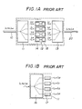
- Fig. 1A shows the conventional optical wavelength-division switching system which comprises an input and output single-mode optical fibers 10 and 20, an optical variable wavelength filter 11, means 12 for converting the wavelengths of optical signals in accordance with the specified switching condition, and an optical combiner 13.
- Each of the wavelength converting means 12 includes an optical-electrical converter 14 and an electrical-optical converter 15.
- Fig. 2A shows the optical variable wavelength filter 11 including an optical branching means 16 and optical filters 17 each having a passing-through wavelength band different from others.
- a WDM optical signal of four wavelengths ⁇ 1, ⁇ 2, ⁇ 3 and ⁇ 4 is supplied from the input single-mode optical fiber 10 to the optical branching means 16 to be divided into four optical signals.
- Each of the four optical signals still includes the four wavelengths ⁇ 1 to ⁇ 4, and an optical signal of the wavelength ⁇ 2 is passed through the first optical filter 17, and optical signals of the wavelengths ⁇ 1, ⁇ 3 and ⁇ 4 are respectively passed through the second to fourth optical filters 17 depending on predetermined passing-through bands thereof.
- the first to fourth optical signals having the individual wavelengths ⁇ 2, ⁇ 1, ⁇ 3 and ⁇ 4 are respectively converted to the first to fourth electric signals having the individual wavelengths ⁇ 1, ⁇ 2, ⁇ 3, and ⁇ 4 by the corresponding optical-electrical converters 14.
- the first to fourth electric signals are respectively converted to the first to fourth optical signals by the corresponding electrical-optical converters 15.
- the optical signals of the wavelengths ⁇ 1 and ⁇ 2 are switched to each other, while the optical signals of the wavelengths ⁇ 3 and ⁇ 4 remain unswitched
- the first to fourth optical signals are combined in the optical combiner 13 to produce a WDM optical signal which is switched between the optical signals of the wavelengths ⁇ 1 and ⁇ 2.
- the WDM optical signal thus combined is supplied to the output single-mode fiber 20.
- the optical communication system comprises a transmitting station 100, single-mode optical fibers 110 and 120, an optical wavelength-division switching system 130, and a receiving station 140.
- the transmitting station 100 includes the first to fourth laser diodes 101 to 104 from which the first to fourth optical signals of wavelength ⁇ 1, ⁇ 2, ⁇ 3 and ⁇ 4 are radiated, and an optical fixed wavelength multiplexer 105 for combining the first to fourth optical signals.
- the first to fourth optical signals have been modulated by transmitting signals of channels 1 to 4.
- the receiving station 140 includes an optical fixed wavelength filter 145, and the first to fourth optical-electrical cnverters 141 to 144.
- the optical signals of the wavelengths ⁇ 1 to ⁇ 4 are combined in the optical fixed wavelength multiplexer 105 to produce a WDM optical signal which is then propagated through the single-mode optical fiber 110.
- the DWM optical signal is demultiplexed into four light signals of wavelengths ⁇ 1 to ⁇ 4.
- the optical signal of the wavelength ⁇ 1 is converted to the optical signal of the wavelength ⁇ 4 therein.
- the optical signals of the wavelengths ⁇ 2, ⁇ 3 and ⁇ 4 are converted to the optical signals of ⁇ 3, ⁇ 2 and ⁇ 1 therein respectively.
- the optical signals of the wavelengths ⁇ 4 to ⁇ 1 thus converted are combined therein to produce a WDM optical signal which is then propagated through the single-mode optical fiber 120.
- the WDM optical signal is demultiplexed in the optical fixed wavelength filter 145 into four optical signals of the wavelengths ⁇ 1 to ⁇ 4.
- the light signal of the wavelength ⁇ 1 is converted in the first optical-electrical converter 141 to the first electric signal which is then supplied to the channel 4.
- the optical signals of the wavelengths ⁇ 2 to ⁇ 4 are respectively converted in the second to fourth optical-electrical converter 142 to 144 to the second to fourth electric signals which are then supplied to the channels 3 to 1.
- the transmitting signals of the channels 1 to 4 in the transmitting station 100 are switched to the receiving signals of the channels 4 to 1 by means of the optical wavelength-division switching system 130.
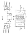
- Fig. 3 shows the optical wavelength-division switching system 130 which is applied to the optical communication system shown in Fig. 2.
- the optical wavelength-division switching system 130 comprises a optical branching means 150, the first to fourth optical heterodyne detection system 151 to 154, the first to fourth electrical-optical converters 161 to 164, and an optical combiner 170.
- Fig. 4 shows one of the first to fourth optical heterodyne detection systems 151 to 154 which comprises an optical combiner 180 having the first to fourth terminals 181 to 184, an isolator 185 connected through an optical fiber 186 to the second terminal 182 of the optical combiner 180, a local oscillation light source 186 for radiating a local oscillation light, a control circuit 187 for controlling a frequency of the local oscillation light in accordance with a control signal to be applied to a terminal 188 thereof, an optical-electrical converter 189 for converting an output of the third terminal 183 of the optical combiner 180 to an electric signal, an amplifier 190 for amplifying the electric signal of the optical-electrical converter 189, and a demodulating circuit 191 for reproducing a receiving signal to be applied through a terminal 192 thereof to one of the electrical-optical converters 161 to 164.
- first to fourth optical heterodyne detection systems 151 to 154 are adopted, these detection systems may be replaced by the first to fourth homodyne detection systems respectively.
- the features of such an optical heterodyne and homodyne detection systems are described on pages 73 to 80 of "Technical Digest of IOOC-ECOC '85", Kunststoffia, Oct. 1 - 4, 1985 vol. II along with the experimental results recently conducted.
- One of the features thereof is that a higher selection of wavelength channels is obtained.
- This advantageous feature makes it possible that such an optical heterodyne or homodyne detection system is used for an optical-electrical conversion type of an optical variable wavelength filter.
- an electric signal corresponding to a predetermined signal in a WDM optical signal can be detected in a case where a local oscillation light is swept in regard to its wavelength to be combined with the WDM optical signal.
- crosstalk is completely negligible between channels in a case where the interval of channels is to be set by more than five times the signal band width. This means that the multiple degree of signals becomes bigger by more than one figure as compared to a normal WDM system using an optical filter and multiplexer.
- a receiving sensitivity is improved by more than 10dB as compared to a direct detecting system so that power loss is also negligible in an optical branching means even if an optical heterodyne or homodyne detection system is combined to the optical branching means to provide a variable wavelength filter.
- a bigger scale of an optical wavelength-division switching system is obtained because frequency bands of light are effectively utilized in a case where an optical heterodyne or homodyne detection system is introduced into an optical-electrical conversion type of an optical filter in an optical wavelength-division switching system.
- the first to fourth optical signals which are modulated by the transmitting signals in the channel 1 to 4 are radiated from the first to fourth laser diodes 101 to 104.
- the transmission rate thereof is 140Mb/s
- the modulation thereof is of a binary optical frequency shift keying (FSK) in which the amount of the deviation is 280MHz.
- control signals are applied through another optical fiber or electric cable (not shown) to the terminal 188 of the control unit 187 in each of the optical heterodyne detection systems 151 to 154.
- the control signals can be of electric signals because the switching is not necessary to be performed in each bit or block of light signals in the optical wavelength-division switching system, although it is necessarily required to do so in a time-division switching system.
- control signals may be transmitted through the optical fiber 110 or 120 along with the optical signals in the form of a WDM optical signal.
- the first to fourth optical signal, the frequency and wavelengthof which are ⁇ 1 to ⁇ 4 and ⁇ 1 to ⁇ 4 respectively, are combined in the optical fixed wavelength multiplexer 105 to be of a WDM optical signal which is then propagated through the optical fiber 110.
- the WDM optical signal is divided into four WDM optical signals in the optical branching means 150 in the optical wavelength-division switching system 130.
- the four WDM optical signals are supplied to the corresponding optical heterodyne detection systems 151 to 154 respectively.
- one of the four outputs of the optical branching means 150 is supplied to the first terminal 181 of the optical combiner 180 to be combined with the local oscillation light which is supplied through the optical fiber 180 to the second terminal 182 thereof.
- the optical-electrical converter 189 At the third and fourth terminals 183 and 184 of the optical combiner 180, two outputs of the optical signal thus combined are obtained.
- One of the two outputs of the optical combiner 180 is supplied to the optical-electrical converter 189 to produce an electric intermediate frequency signal which is then amplified in the amplifier 190.
- the intermediate frequency signal thus amplified is demodulated in the demodulating circuit 191 to produce a receiving signal which is then applied through the terminal 192 to the corresponding one of the first to fourth electrical-optical converter 161 to 164.
- the aforementioned local oscillation light is radiated from the local oscillation light source 186 to be passed through the isolator 185 thereby to be supplied to the second terminal 182 of the optical combiner 180.
- the local oscillation light source 186 is driven to control the frequency of the local oscillation light depending on the control signals applied to the terminal 188 of the control unit 187.
- the local oscillation light source 186 is of a wavelength tunable DBR semiconductor laser in which an oscillation wavelength thereof can be controlled, and a single wavelength oscillation is obtained.
- the outputs of the respective optical heterodyne detection systems 151 to 154 are converted in the corresponding electrical-optical converters 161 to 164 each including a driving circuit and a semiconductor laser so that optical signals modulated in a binary optical FSK, the transmission rate and deviation amount of which are 140Mb/s and 280MHz respectively, are produced therein.
- the oscillation frequency thereof is controlled to be fixed values to be described in more detail later.
- the optical signals of the wavelength ⁇ 1 to ⁇ 4 are switched thereamong in accordance with the fixed frequency values in the converters 161 to 164.
- the optical signals of the wavelengths ⁇ 1 to ⁇ 4 thus switched are combined in the optical combiner 170 to produce a WDM optical signal which is then supplied to the single-mode optical fiber 120.
- the switching operation will be explained in more detail later.
- optical branching means 150 such a means as using an optical fiber fused type of 2 ⁇ 2 couplers which are connected by a predetermined number of steps may be used therefor.
- a wavelength tunable DBR laser diode which is used for the local oscillation light source 186 may be the same as a laser diode described on pages 63 to 65 of "Electronics Letters", vol. 21, 1985. Further, such an optical heterodyne detection system as shown in Fig. 4 is described in detail on pages 1022 and 1023 of "Electronics Letters", vol. 20, 1984.
- the optical signals are radiated with a frequency interval 2GHz (a wavelength interval 0.16 ⁇ ) to avoid crosstalk therebetween from the laser diodes 101 to 104 in the transmitting station 100 (Fig. 5A).
- Each of the optical signals has one of the individual oscillation frequencies ⁇ 1, ⁇ 2, ⁇ 3 and ⁇ 4, and the waveform thereof is of a double-humped shape due to FSK (Frequency Shift Keying) modulation in accordance with the corresponding one of transmitting signals in the channels 1 to 4.
- the optical signals thus FSK modulated are of 140Mb/s in the transmission rate, and of 280MHz in the frequency deviation as described before.
- the frequency and wavelength thereof are, for instance, as follows.
- the local oscillation lights of predetermined frequencies ⁇ a , ⁇ b , ⁇ c and ⁇ d are radiated from the local oscillation light sources 186 under the control of the control units 187 (Fig. 5B).
- the intermediate frequency is produced in each of the optical heterodyne detection systems 151 to 154 so that a double-humped spectrum of FSK signal having a frequency deviation 280MHz on the left and right sides of the center frequency 600MHz is obtained (Fig. 5C).
- One side or both sides of the double-humped spectrum are electrically filtered to be demodulated thereby reproducing a baseband signal.
- a baseband signal which is carried by the optical signal of the wavelength ⁇ 4 is reproduced.
- baseband signals which are carried by the optical signals of the wavelength ⁇ 3, ⁇ 2 and ⁇ 1 are reproduced respectively in the optical heterodyne detection systems 152 to 154.
- the electrical-optical converters 161 to 164 each of a phase tunable type DFB laser diode, for instance, as described on pages 5 to 7 of "Electronics Letters", vol. 22, 1986 are controlled to produce oscillation frequencies ⁇ 1, ⁇ 2, ⁇ 3 and ⁇ 4 respectively.
- the optical signal of the frequency ⁇ 4 is converted to the optical signal of the freqneucy ⁇ 1
- the optical signals of the frequencies ⁇ 3, ⁇ 2 and ⁇ 1 are converted to the optical signals of the frequencies ⁇ 2, ⁇ 3 and ⁇ 4 as follows.
- the switching combination of the invention is not limited to the above example, but may be changed according to the necessity of an optical communication system.
- a wavelength tunable light source has been already provided to cover the region of 100GHz, and even more is possible to cover the region of 700GHz for the local oscillation light source 186 as described on page 788 of "The transactions of The IECE Japan", vol. E68, 1985. Therefore, a bigger scale of 35 or 70 channels can be selected by using such a local oscillation light source in a case where a frequency interval as defined before is 2GHz or 10GHz.
- an amplitude-shift-keying(ASK), phase-shift-keying (PSK) etc. may be utilized therein, if the construction thereof is adapted thereto.
- an optical wavelength-division switching system according to the invention can be applied even to an optical system which has not been designed to include an optical heterodyne detection system for the reason why an optical heterodyne or homodyne detection system can be applied to an intensity modulation system in which a practically used direct detection is performed, if a light carrier wavelength is stabilized therein.
- an optical heterodyne detection and direct detection may be combined in such a manner that an optical wavelength-division switching system is used in a trunk line as a tandem switch, while a direct detector is used in a subscriber's line.
- an optical branching means having no dependence on wavelength is used to introduce optical signals to an optical heterodyne detection system in the embodiment, it may be combined with a variable wavelength filter.
- a filtering characteristic of an optical heterodyne detection system is variable based on a variabe frequency of a local oscillation light source thereof, the filtering characteristic thereof may be fixed based on a fixed frequency of a local oscillation light source, if a wavelength of an electrical-optical converter is made variable.
- the construction of the embodiment is considered to be superior to the modified construction mentioned above because the connection of a plurality of lines to one line (1:n) is difficult to be performed.
Applications Claiming Priority (2)
| Application Number | Priority Date | Filing Date | Title |
|---|---|---|---|
| JP61245842A JPH0636621B2 (ja) | 1986-10-15 | 1986-10-15 | 光交換機 |
| JP245842/86 | 1986-10-15 |
Publications (2)
| Publication Number | Publication Date |
|---|---|
| EP0264119A2 true EP0264119A2 (de) | 1988-04-20 |
| EP0264119A3 EP0264119A3 (de) | 1989-04-05 |
Family
ID=17139662
Family Applications (1)
| Application Number | Title | Priority Date | Filing Date |
|---|---|---|---|
| EP87115017A Withdrawn EP0264119A3 (de) | 1986-10-15 | 1987-10-14 | Optisches Wellenlängenmultiplexvermittlungssystem |
Country Status (3)
| Country | Link |
|---|---|
| US (1) | US4807227A (de) |
| EP (1) | EP0264119A3 (de) |
| JP (1) | JPH0636621B2 (de) |
Cited By (5)
| Publication number | Priority date | Publication date | Assignee | Title |
|---|---|---|---|---|
| EP0223258A2 (de) * | 1985-11-22 | 1987-05-27 | Nec Corporation | Optisches Wellenlängenmultiplexvermittlungssystem mit Wellenlängenschaltlichtmodulatoren |
| EP0351729A2 (de) * | 1988-07-18 | 1990-01-24 | Fujitsu Limited | Optisches Vermittlungssystem |
| GB2227623A (en) * | 1989-01-28 | 1990-08-01 | Stc Plc | Optical fibre network |
| WO1992010770A1 (en) * | 1990-12-07 | 1992-06-25 | Telefonaktiebolaget Lm Ericsson | A method and arrangement for optical switching |
| EP1099321A1 (de) * | 1998-07-21 | 2001-05-16 | Corvis Corporation | Optische nachrichten übertragungs system,vorrichtungen und verfahren |
Families Citing this family (31)
| Publication number | Priority date | Publication date | Assignee | Title |
|---|---|---|---|---|
| JPH0681119B2 (ja) * | 1986-04-17 | 1994-10-12 | 日本電気株式会社 | 波長多重光伝送方式 |
| JP2540935B2 (ja) * | 1989-03-16 | 1996-10-09 | 日本電気株式会社 | 一括偏波制御方法 |
| US5173794A (en) * | 1989-03-16 | 1992-12-22 | Bell Communications Research, Inc. | Wavelength division multiplexing using a tunable acousto-optic filter |
| FR2665039B1 (fr) * | 1990-07-17 | 1994-03-25 | France Telecom | Systeme de commutation optique de signaux multiplexes en frequence. |
| US5214527A (en) * | 1990-09-26 | 1993-05-25 | Bell Communications Research, Inc. | Electronically switched multiple-channel optical receiver |
| US5109447A (en) * | 1991-03-04 | 1992-04-28 | The Boeing Company | High-powered, spectrally flat, very broadband optical source including optical coupler and method using same |
| JPH04334134A (ja) * | 1991-05-10 | 1992-11-20 | Mitsubishi Electric Corp | 通信方式 |
| JP2770613B2 (ja) * | 1991-07-29 | 1998-07-02 | 日本電気株式会社 | 光シグナリング伝送方式 |
| GB2260872B (en) * | 1991-09-20 | 1995-10-25 | Sharp Kk | An optical transmission system |
| US5504609A (en) * | 1995-05-11 | 1996-04-02 | Ciena Corporation | WDM optical communication system with remodulators |
| US9191117B2 (en) * | 1995-05-11 | 2015-11-17 | Ciena Corporation | High-speed optical transponder systems |
| US6233077B1 (en) * | 1995-05-11 | 2001-05-15 | Ciena Corporation | Remodulating channel selectors for WDM optical communication systems |
| US5712932A (en) * | 1995-08-08 | 1998-01-27 | Ciena Corporation | Dynamically reconfigurable WDM optical communication systems with optical routing systems |
| JP3042605B2 (ja) * | 1997-02-14 | 2000-05-15 | 日本電気株式会社 | 光送信器 |
| US6016212A (en) * | 1997-04-30 | 2000-01-18 | At&T Corp | Optical receiver and demultiplexer for free-space wavelength division multiplexing communications systems |
| FR2767975B1 (fr) * | 1997-09-04 | 1999-10-15 | Alsthom Cge Alcatel | Dispositif preamplificateur optique |
| US6120190A (en) | 1997-11-26 | 2000-09-19 | Lasertron, Inc. | Spatially variable bandpass filter monitoring and feedback control of laser wavelength especially in wavelength division multiplexing communication systems |
| FR2771570B1 (fr) * | 1997-11-27 | 2004-09-24 | Alsthom Cge Alkatel | Reduction de la gigue de collision par echange de longueurs d'onde dans un systeme de transmission a fibre optique a signaux solitons et a multiplexage de longueur d'onde |
| US6388782B1 (en) | 1998-06-01 | 2002-05-14 | Sarnoff Corporation | Multi-wavelength dense wavelength division multiplexed optical switching systems |
| US6014237A (en) * | 1998-06-01 | 2000-01-11 | Sarnoff Corporation | Multiwavelength mode-locked dense wavelength division multiplexed optical communication systems |
| US6192058B1 (en) | 1998-09-18 | 2001-02-20 | Sarnoff Corporation | Multiwavelength actively mode-locked external cavity semiconductor laser |
| US6661973B1 (en) | 1999-06-04 | 2003-12-09 | David R. Huber | Optical transmission systems, apparatuses, and methods |
| US7209660B1 (en) * | 1999-12-29 | 2007-04-24 | Forster Energy Llc | Optical communications using heterodyne detection |
| US7447436B2 (en) * | 1999-12-29 | 2008-11-04 | Forster Energy Llc | Optical communications using multiplexed single sideband transmission and heterodyne detection |
| US7146103B2 (en) * | 1999-12-29 | 2006-12-05 | Forster Energy Llc | Optical communications using multiplexed single sideband transmission and heterodyne detection |
| US6407846B1 (en) | 2001-03-16 | 2002-06-18 | All Optical Networks, Inc. | Photonic wavelength shifting method |
| US20020131100A1 (en) * | 2001-03-16 | 2002-09-19 | Myers Michael H. | Method for photonic wavelength error detection |
| US7075954B2 (en) * | 2001-05-29 | 2006-07-11 | Nl Nanosemiconductor Gmbh | Intelligent wavelength division multiplexing systems based on arrays of wavelength tunable lasers and wavelength tunable resonant photodetectors |
| US20030026199A1 (en) * | 2001-08-03 | 2003-02-06 | Myers Michael H. | Code-division, minimum-shift-keying optical multiplexing |
| US6865345B2 (en) * | 2001-08-28 | 2005-03-08 | Agilent Technologies, Inc. | Frequency translating devices and frequency translating measurement systems that utilize light-activated resistors |
| TWI563304B (en) * | 2012-05-22 | 2016-12-21 | Hon Hai Prec Ind Co Ltd | Laser signal transmitting device |
Citations (1)
| Publication number | Priority date | Publication date | Assignee | Title |
|---|---|---|---|---|
| EP0131818A2 (de) * | 1983-07-01 | 1985-01-23 | International Standard Electric Corporation | Optisches Frequenzmultiplexsystem |
Family Cites Families (5)
| Publication number | Priority date | Publication date | Assignee | Title |
|---|---|---|---|---|
| US3851167A (en) * | 1972-12-11 | 1974-11-26 | Itt | Light-guide communication system with image intensifier repeater elements |
| JPS6010612B2 (ja) * | 1977-03-14 | 1985-03-19 | 日本電気株式会社 | ヘテロダイン検波光通信装置 |
| EP0110388B1 (de) * | 1982-11-29 | 1987-10-07 | Nec Corporation | Optisches Zeitmultiplexvermittlungssystem das optische bistabile Einrichtungen anwendet |
| JPS60172841A (ja) * | 1984-01-27 | 1985-09-06 | Nippon Telegr & Teleph Corp <Ntt> | 光スイツチ |
| JPS60254991A (ja) * | 1984-05-31 | 1985-12-16 | Nec Corp | 時分割光交換機 |
-
1986
- 1986-10-15 JP JP61245842A patent/JPH0636621B2/ja not_active Expired - Lifetime
-
1987
- 1987-10-14 EP EP87115017A patent/EP0264119A3/de not_active Withdrawn
- 1987-10-15 US US07/108,679 patent/US4807227A/en not_active Expired - Lifetime
Patent Citations (1)
| Publication number | Priority date | Publication date | Assignee | Title |
|---|---|---|---|---|
| EP0131818A2 (de) * | 1983-07-01 | 1985-01-23 | International Standard Electric Corporation | Optisches Frequenzmultiplexsystem |
Non-Patent Citations (4)
| Title |
|---|
| ELEKTRONIK, vol. 34, no. 13, June 1985, pages 104-109, Munich, DE; P. LANGE: "250 000 ]bertragungskan{le auf einer Glasfaser?" * |
| IEEE JOURNAL ON SELECTED AREAS IN COMMUNICATIONS, vol. SAC-4, no. 4, July 1986, pages 542-550, IEEE, New York, US; C. BAACK et al.: "Architecture of broad-band communications systems" * |
| JOURNAL OF OPTICAL COMMUNICATIONS, vol. 3, no. 3, September 1982, pages 93-100, Fachverlag Schiele & Schön, Berlin, DE; R. Th. KERSTEN et al.: "Wavelength division multiplexing in optical communications systems" * |
| PATENT ABSTRACTS OF JAPAN, vol. 10, no. 236 (E-428)[2292], 15th August 1986; & JP-A-61 67 388 (NIPPON TELEGRAPH & TELEPHONE CORP.) 07-04-1986 * |
Cited By (11)
| Publication number | Priority date | Publication date | Assignee | Title |
|---|---|---|---|---|
| EP0223258A2 (de) * | 1985-11-22 | 1987-05-27 | Nec Corporation | Optisches Wellenlängenmultiplexvermittlungssystem mit Wellenlängenschaltlichtmodulatoren |
| EP0223258A3 (en) * | 1985-11-22 | 1989-04-19 | Nec Corporation | Wavelength division optical switching system having wavelength switching light modulators |
| EP0351729A2 (de) * | 1988-07-18 | 1990-01-24 | Fujitsu Limited | Optisches Vermittlungssystem |
| EP0351729A3 (de) * | 1988-07-18 | 1992-01-15 | Fujitsu Limited | Optisches Vermittlungssystem |
| EP0741498A2 (de) * | 1988-07-18 | 1996-11-06 | Fujitsu Limited | Optische Kommunikationsanordnung |
| EP0741498A3 (de) * | 1988-07-18 | 1997-05-28 | Fujitsu Ltd | Optische Kommunikationsanordnung |
| GB2227623A (en) * | 1989-01-28 | 1990-08-01 | Stc Plc | Optical fibre network |
| WO1992010770A1 (en) * | 1990-12-07 | 1992-06-25 | Telefonaktiebolaget Lm Ericsson | A method and arrangement for optical switching |
| US5450224A (en) * | 1990-12-07 | 1995-09-12 | Telefonaktiebolaget Lm Ericsson | Method and arrangement for optical switching |
| EP1099321A1 (de) * | 1998-07-21 | 2001-05-16 | Corvis Corporation | Optische nachrichten übertragungs system,vorrichtungen und verfahren |
| EP1099321A4 (de) * | 1998-07-21 | 2007-05-02 | Corvis Corp | Optische nachrichten übertragungs system,vorrichtungen und verfahren |
Also Published As
| Publication number | Publication date |
|---|---|
| EP0264119A3 (de) | 1989-04-05 |
| JPS6399697A (ja) | 1988-04-30 |
| JPH0636621B2 (ja) | 1994-05-11 |
| US4807227A (en) | 1989-02-21 |
Similar Documents
| Publication | Publication Date | Title |
|---|---|---|
| EP0264119A2 (de) | Optisches Wellenlängenmultiplexvermittlungssystem | |
| EP0367452B1 (de) | Photonische Schalterarchitektur mit Kode- und Wellenlängenmultiplexierung | |
| US5212579A (en) | Method and apparatus for communicating amplitude modulated signals over an optical communication path | |
| US5596436A (en) | Subcarrier multiplexing with dispersion reduction and direct detection | |
| US5107360A (en) | Optical transmission of RF subcarriers in adjacent signal bands | |
| US6810215B1 (en) | Optical repeater converting wavelength and bit rate between networks | |
| US6922431B1 (en) | Communication using spread spectrum methods over optical fibers | |
| US4991975A (en) | Division multiplexing and demultiplexing means lightwave communication system comprising optical time | |
| KR19980081203A (ko) | 스플리터가 없는 광 방송 스위치 | |
| US5170273A (en) | Wavelength-division switching system for optical frequency-shift keying signals | |
| US7376356B2 (en) | Optical data transmission system using sub-band multiplexing | |
| US7209660B1 (en) | Optical communications using heterodyne detection | |
| JPH07202818A (ja) | 同調可能な集積型光フィルタ装置 | |
| EP0317352B1 (de) | Optisches Wahlnetzwerk | |
| CA1244519A (en) | Optical networks | |
| US5416625A (en) | Optical demultiplexing system | |
| JP2890031B2 (ja) | ミリ波信号光多重伝送方式及び装置 | |
| WO2003032532A1 (en) | Optical signal transmission | |
| JP4586305B2 (ja) | 多重化光伝送方法及び多重化光伝送装置 | |
| JPH0818538A (ja) | 光波長多重ネットワークシステム | |
| RU2124812C1 (ru) | Способ передачи сигналов синхронных цифровых волоконно-оптических систем методом спектрально-кодового мультиплексирования и устройство для его осуществления | |
| Khoe | Coherent multicarrier lightwave technology for flexible capacity networks | |
| JPS63148726A (ja) | 波長分割多重双方向光通信装置 | |
| JP2809796B2 (ja) | コヒーレント光伝送装置 | |
| JP3286094B2 (ja) | 光波長多重ネットワークシステム |
Legal Events
| Date | Code | Title | Description |
|---|---|---|---|
| PUAI | Public reference made under article 153(3) epc to a published international application that has entered the european phase |
Free format text: ORIGINAL CODE: 0009012 |
|
| 17P | Request for examination filed |
Effective date: 19871014 |
|
| AK | Designated contracting states |
Kind code of ref document: A2 Designated state(s): DE FR GB |
|
| PUAL | Search report despatched |
Free format text: ORIGINAL CODE: 0009013 |
|
| AK | Designated contracting states |
Kind code of ref document: A3 Designated state(s): DE FR GB |
|
| 17Q | First examination report despatched |
Effective date: 19910621 |
|
| STAA | Information on the status of an ep patent application or granted ep patent |
Free format text: STATUS: THE APPLICATION IS DEEMED TO BE WITHDRAWN |
|
| 18D | Application deemed to be withdrawn |
Effective date: 19920103 |
|
| RIN1 | Information on inventor provided before grant (corrected) |
Inventor name: KAZUHISA, KAEDEC/O NEC CORPORATION Inventor name: MINORU, SHIKADAC/O NEC CORPORATION Inventor name: MASAHIKO, FUJIWARAC/O NEC CORPORATION |