EP0263696B1 - Laser beam scanner - Google Patents
Laser beam scanner Download PDFInfo
- Publication number
- EP0263696B1 EP0263696B1 EP87308889A EP87308889A EP0263696B1 EP 0263696 B1 EP0263696 B1 EP 0263696B1 EP 87308889 A EP87308889 A EP 87308889A EP 87308889 A EP87308889 A EP 87308889A EP 0263696 B1 EP0263696 B1 EP 0263696B1
- Authority
- EP
- European Patent Office
- Prior art keywords
- hologram
- laser beam
- scanning
- holograms
- window
- Prior art date
- Legal status (The legal status is an assumption and is not a legal conclusion. Google has not performed a legal analysis and makes no representation as to the accuracy of the status listed.)
- Expired - Lifetime
Links
Images


Classifications
-
- G—PHYSICS
- G06—COMPUTING; CALCULATING OR COUNTING
- G06K—GRAPHICAL DATA READING; PRESENTATION OF DATA; RECORD CARRIERS; HANDLING RECORD CARRIERS
- G06K7/00—Methods or arrangements for sensing record carriers, e.g. for reading patterns
- G06K7/10—Methods or arrangements for sensing record carriers, e.g. for reading patterns by electromagnetic radiation, e.g. optical sensing; by corpuscular radiation
- G06K7/10544—Methods or arrangements for sensing record carriers, e.g. for reading patterns by electromagnetic radiation, e.g. optical sensing; by corpuscular radiation by scanning of the records by radiation in the optical part of the electromagnetic spectrum
- G06K7/10821—Methods or arrangements for sensing record carriers, e.g. for reading patterns by electromagnetic radiation, e.g. optical sensing; by corpuscular radiation by scanning of the records by radiation in the optical part of the electromagnetic spectrum further details of bar or optical code scanning devices
- G06K7/10861—Methods or arrangements for sensing record carriers, e.g. for reading patterns by electromagnetic radiation, e.g. optical sensing; by corpuscular radiation by scanning of the records by radiation in the optical part of the electromagnetic spectrum further details of bar or optical code scanning devices sensing of data fields affixed to objects or articles, e.g. coded labels
- G06K7/10871—Methods or arrangements for sensing record carriers, e.g. for reading patterns by electromagnetic radiation, e.g. optical sensing; by corpuscular radiation by scanning of the records by radiation in the optical part of the electromagnetic spectrum further details of bar or optical code scanning devices sensing of data fields affixed to objects or articles, e.g. coded labels randomly oriented data-fields, code-marks therefore, e.g. concentric circles-code
Definitions
- the present invention relates to laser beam scanners, utilising holograms and laser beams, for example for reading bar codes or the like.
- Such a scanner employs holograms in its optical system to cause a laser beam to be directed in accordance with a predetermined scanning pattern.
- Use of such a scanner, giving a complicated scanning pattern, can facilitate the construction of a bar code reader of high reliability and accuracy.
- Such a bar code reader can be utilised in a supermarket or the like as terminal equipment of a POS (point of sales) system which manages sales data in Real Time by direct input of the sales data to a computer from cash registers.
- POS point of sales
- the bar code reader is placed on a register table with a cash register, and a bar code marked on a sales article is scanned and read by the reader while the article is moved thereabove by hand.
- the bar code reader it is desirable that the bar code reader be small in size, especially in height, for the sake of operational convenience and economy of space.
- Such use of holograms to simultaneously function as a conventional rotatable polygon mirror and a conventional scanning lens system is similar in principle to the use of a rotating hologram disc in a scanning system described in EP-A-0132956.
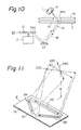
- Figure 10 shows a schematic side view of the bar code reader, which employs a laser beam scanning system 10 comprising a motor 11 driving a rotatable hologram disc 12, having a plurality of hologram facets, a mirror 13, a stationary hologram member 2, a window cover 14 and a scanning window 15 (provided by a portion of the stationary hologram member 2 that is exposed through an opening 14a in the window cover 14).
- Scattered light 18, from the bar code 17 propagates in the direction opposite to the scanning beam 16, as illustrated by broken lines, and reaches the hologram disc 12, where the scattered light 18 is diffracted towards an optical detector (not shown) which responds to the received light so as to provide an output representative of the bar code 17.
- the scattered light 18, from the bar code 17, is divergent until it reaches the stationary hologram member 2.
- scattered light passing back through the opening 14a to the hologram member 2 is not widely divergent, because of the positional relationship between the hologram member 2 and the bar code 17.
- This scattered light is converted by the stationary hologram member 2 to a substantially parallel light beam that passes to the hologram disc 12 without divergence.
- the scanning beam emerging via the opening 14a scans the surface of the bar code 17 so as to trace out a scanning line thereover.
- a plurality of scanning lines are required to be traced out in different directions.
- Figure 11 shows a perspective view of the scanning window 15 constituted by the exposed portion of the stationary hologram member 2, which member comprises a transparent substrate 21 and strip-form holograms 22, 23 and 24 formed on the substrate 21.
- a scanning pattern comprising a plurality of scanning lines 220, 230 and 240, corresponding respectively to the hologram strips 22, 23 and 24 and intersecting each other, is formed at some distance above the stationary hologram member 2.
- the bar code 17 may not always be scanned by the scanning beam.
- Fig. 12(a) which relates to a plane close to the window cover 14
- the bar code 17 being moved along a broken line 1 is read, but the bar code being moved along either of the broken lines 2 and 3 is not read. This is because, with the bar code 17 inclined as depicted in Fig. 12(a), only the scanning line 240 can pass through the entire length of the bar code.
- the scanning lines 220 and 230 cannot pass through the entire lengh of the bar code, owing to the difference in orientation between the scanning lines and the bar code 17. Therefore, the bar code 17 being moved along the broken line 2 or 3, in the illustrated plane close to the window cover 14, cannot be read because the scanning line 240 does not extend as far as the broken line 2 or 3.
- a laser beam scanner comprising: a hologram window 8 incorporating a plurality of layer-form holograms, arranged in overlying relationship to one another; and optical means arranged for causing a laser beam to be incident on the hologram window and to scan the said layer-form holograms so that diffraction of the beam by the individual holograms produces respective scanning beams which emerge from a main face of the hologram window so as to trace out in turn, in an operation space adjacent to the said main face, respective scanning lines which intersect one another; the arrangement being such that each of the said scanning beams, after leaving the ,hologram that produced that beam by diffraction, emerges from the said main face without having been incident upon any other one of the holograms at such an angle as to satisfy the Bragg condition therein.
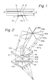
- Fig. 1 shows a hologram window 3 having incorporated therein at least two layer-form holograms, comprising strip-form holograms 31 and 32, arranged in an overlying relationship to one another so that the hologram strip 32 crosses the strip 31.
- a laser beam scanner employing the window 3 has an optical system for directing laser beams 33 and 34 so that they are diffracted respectively by the strip-form holograms 31 and 32, thereby producing respective scanning beams that emerge from the scanner by way of the upper main face of the window 3.
- An optical detector (not shown) is installed in the scanner to detect signal light scattered back, from an article under examination, through the hologram strips 31 and 32 of the hologram window 3.
- Continuous scanning beams can be obtained by an arrangement wherein the scanning beam 34 diffracted by the lower hologram strip 31 impinges on the upper hologram strip 32 at an angle such that the Bragg condition (described below) is not satisfied in that strip, and wherein the laser beam 33 to be diffracted by the upper hologram 32 is incident on the lower hologram strip 31 at an angle such that the Bragg condition is not satisfied in the strip 31.
- the scanning beam produced by diffraction in the lower hologram strip 31 then passes through the upper hologram without being diffracted thereby, and the laser beam to be diffracted by the upper hologram strip 32 passes through the lower hologram strip 31 without being diffracted thereby.
- a window cover defining the lowest part of the usable operation space can be positioned very close to the hologram window, enabling the overall height of the space needed for the scanner to be kept desirably small.
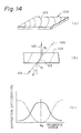
- Fig. 14(a) shows interference fringes 103 in a layer-form hologram 102.
- Light passing through the hologram layer 102 is diffracted in a manner dependent upon the pattern of the interference fringes 103.
- Each interference fringe 103 is inclined, as seen in a cross-section of the hologram layer 102, as illustrated in Figure 14(b).
- a laser beam 104 is incident on the hologram layer 102 at an angle ⁇ as shown, so that it impinges on the fringes 103 at a glancing angle ⁇ 1, diffraction by the interference fringes 103 may cause light to leave the fringes 103 at a glancing angle ⁇ 2 as shown.
- the intensity of the transmitted beam 106 increases in accordance with the deviation of the glancing incidence angle ⁇ 1, of the beam 104, from the Bragg angle ⁇ B , as illustrated in the graph of Figure 14(c).
- the abscissa represents the glancing incidence angle ⁇ 1 of the beam impinging on the hologram, and the ordinate represents the diffraction efficiency.
- the solid line graph represents the diffracted beam 105, the luminous strength (intensity) of which is maximised at the Bragg angle ⁇ B .
- the broken line graph represents the directly transmitted beam 106, the intensity of which is almost zero at the Bragg angle ⁇ B and increases in accordance with the deviation of the incidence angle ⁇ 1 from the Bragg angle ⁇ B .
- a plurality of layer-form holograms are incorporated in a hologram window, disposed in an overlying relationship to one another, the arrangement being such that a laser beam to be diffracted by a particular one of the hologram layers passes first through one or more preceding hologram layers without being significantly diffracted thereby, and the beam diffracted by that particular hologram layer then penetrates succeeding hologram layers without being diffracted significantly thereby.
- This is achieved by ensuring that, where diffraction is to be avoided, the relevant incidence angle of the beam is different from the Bragg angle. In practice, it is generally sufficient to make the difference between the relevant incidence angle and the Bragg angle such that only about one-tenth of the incident beam flux is diffracted.
- Fig. 2 shows components of a hologram window 4 which comprises a first hologram strip 41 formed on a transparent substrate 43 such as a glass plate, and a second hologram strip 42 formed on a transparent substrate 44 such as a glass plate.
- the first hologram strip 41 comprises two strip-form holograms 41a and 41b having respective different diffraction directions.
- the second hologram strip 42 comprises two strip-form holograms 42a and 42b having respective different diffraction directions.
- the hologram window 4 is assembled by fixing two transparent substrates 43 and 44 together in such a manner that the strip 42 overlies and extends transversely with respect to the strip 41, so as to cross thereover.
- a scanning laser beam directed onto the hologram 41a is diffracted thereby and propagated therefrom as a diffracted scanning beam 45a directed so that where it passes through the hologram strip 42 the beam 45a does not satisfy the Bragg condition in the hologram strip 42.
- the scanning beam 45a therefore passes through the transparent substrate 44 and the hologram strip 42 without being significantly diffracted thereby, and traces out a continuous scanning line 46a in a plane above the window 4.
- a scanning laser beam incident on the hologram 41b is diffracted thereby and propagates therefrom as a diffracted scanning beam 45b, the direction of which does not satisfy the Bragg condition in the upper hologram strip 42.
- the scanning beam 45b accordingly penetrates the transparent substrate 44 and the hologram strip 42 without being diffracted, and traces out a continuous scanning line 46b.
- a scanning laser beam directed so that it does not satisfy the Bragg condition in the hologram strip 41 penetrates the lower substrate 43 and the hologram strip 41, without being diffracted significantly thereby, and is incident on the upper hologram strip 42, for example on the strip-form hologram 42a.
- the beam incident on the hologram 42a is diffracted thereby and propagated therefrom as a diffracted scanning beam 47a which traces out a continuous scanning line 48a.
- a scanning laser beam, the direction of which does not satisfy the Bragg condition in the hologram strip 41 penetrates the transparent substrate 43 and the hologram strip 41, without being diffracted significantly thereby, and is incident on the hologram 42b.
- the beam incident on the hologram 42b is diffracted thereby and propagated therefrom as a diffracted scanning beam 47b which traces out a continuous scanning line 48b.
- a hologram window 5 comprises a transparent substrate 53 such as a glass plate, a first hologram strip 51 coated on the lower surface of the transparent substrate 53, and a second hologram strip 52 coated on the upper surface of the transparent substrate 53.
- the first hologram strip 51 comprises two strip-form holograms 51a and 51b having different diffraction directions.
- the second hologram strip 52 comprises two holograms 52a and 52b having different diffraction directions.
- Each of the hologram strips 41, 42, 51 and 52 may comprise phase-type or surface relief-type holograms.
- a scanning laser beam incident on the hologram 51a is diffracted thereby and propagated therefrom as a diffracted scanning beam 55a, the direction of which does not satisfy the Bragg condition in the upper hologram strip 52. Therefore, the scanning beam 55a diffracted by the hologram 51a penetrates the transparent substrate 53 and the upper hologram strip 52 without being diffracted by the hologram strip 52, and traces a continuous scanning line 56a.
- a scanning laser beam incident on the lower hologram 51b is diffracted by the hologram 51b and propagated therefrom as a diffracted scanning beam 55b, the direction of which does not satisfy the Bragg condition in the upper hologram strip 52. Therefore, the scanning beam diffracted by the lower hologram 51b penetrates the transparent substrate 53 and the upper hologram strip 52 without being diffracted, and traces a continuous scanning line 56b.
- a scanning laser beam directed onto the hologram window 5 with an incidence angle not satisfying the Bragg condition in the hologram strip 51 penetrates the hologram strip 51 and the transparent substrate 53 without being diffracted by the hologram strip 51 and is incident on the hologram 52a.
- the incident beam is diffracted by the hologram 52a and propagated therefrom as a diffracted scanning beam 57a which traces a continuous scanning line 58a.
- another scanning laser beam, directed onto the hologram window 5 with an incidence angle not satisfying the Bragg condition in the hologram strip 51 penetrates the transparent substrate 53 and the hologram strip 51 without being diffracted by the hologram strip 51 and is incident on the upper hologram 52b.
- the incident beam is diffracted by the hologram 52b and propagated therefrom as a diffracted scanning beam 57b which traces a continuous scanning line 58b.
- scanning of the bar code 17 by the beam 16 is brought about by deflecting the laser beam by the optical scanning system 10 and directing the resulting scanning beam onto the surface of the bar code 17 via the mirror 13 and the stationary hologram member 2.
- the range of movement of the scanning beam spot at the location of the bar code 17 will therefore depend upon the path length of the scanning beam, from the system 10 to the bar code 17.
- the scanning range of the beam spot at the bar code 17 will be narrowed in accordance with any shortening of the optical distance from the scanning system 10 to the bar code 17, if the scanning angle of the beam at the scanning system 10 remains the same.
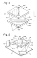
- Figures 4 and 5 illustrate how the optical path length of the scanning laser beam can be kept sufficiently large to give an adequate scanning range at a distance, above a hologram window, that is reduced as compared with the arrangement of Figures 10 and 11.
- a hologram window 6 comprises a first hologram strip 41 formed on a lower transparent substrate 43 and a second hologram strip 42 formed on an upper transparent substrate 44, similar to the embodiment of Figure 2.
- the first hologram strip 41 comprises two strip-form holograms 41a and 41b having different diffraction directions.
- the second hologram strip 42 comprises two strip-form holograms 42a and 42b having different diffraction directions.
- a hologram 62 for introducing a scanning laser beam 61 into the upper transparent substrate 44 is provided at a corner thereof.
- a hologram 64 for introducing a scanning laser beam 63 into the lower transparent substrate 43 is provided at a corner thereof.
- the scanning laser beam 61 is introduced into the transparent substrate 44 through the hologram 62 and propagates in that substrate, undergoing repeated total internal reflections therein, to the hologram 42a or 42b. During the propagation within the transparent substrate 44, the lateral range of movement of the scanning laser beam 61 is gradually widened. Also, the scanning laser beam 63 is introduced into the transparent substrate 43 through the hologram 64 and propagates in that substrate, undergoing repeated total internal reflections therein, to the hologram 41a or 41b. During the propagation within the transparent substrate 43, the lateral range of movement of the scanning laser beam 63 is widened. Thus the path length required to widen the scanning range adequately, i.e. the lateral range of movement of the eventual beam spot on an article to be examined, is obtained by virtue of repeated total internal reflections within each of the transparent substrates.
- a hologram window 5 comprises a first hologram strip 51 formed on a lower surface of a transparent substrate 53, and a second hologram strip 52 formed an upper surface of the transparent substrate 53.
- the hologram strip 51 comprises two strip-form holograms 51a and 51b having different diffraction directions.
- the second hologram 52 comprises two strip-form holograms 52a and 52b having different diffraction directions.
- a floor mirror 71 and a plurality of side mirrors 72 and 73 are disposed below the hologram window 5.
- a scanning laser beam 74 which is approximately parallel to the hologram window 5, impinges on the side mirrors 72 and 73 in turn, is reflected by each of the mirrors 72 and 73, further reflected by the floor mirror 71, and then propagates to the hologram strip 51 or 52.
- the path length from that system to the window 5 is made sufficiently large, to give an adequate scanning range immediately above that window.
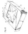
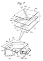
- a laser beam scanner embodying the present invention will now be described with reference to Figures 6 to 9.
- the scanner is housed in a plastic case 80 which comprises an upper cover 81 and a lower box 82.
- a rectangular opening 83 is formed in the upper cover 81, and a vent 84 for a cooling fan is formed by a plurality of slits in one side wall of the lower box 82.
- a confirmation lamp 85 for indicating whether or not a bar code has been read is provided on the upper cover 81.
- a window cover 87 having an opening shaped like an is disposed inside the upper cover 81 at the location of the opening 83, and a hologram window is disposed below the window cover 87.
- the case 80 can be very compact.
- the case 80 can have a height of less than 85 mm (in fact a height of 79 mm has been achieved) and the longitudinal x lateral dimensions can be less than 250 mm x 310 mm (in fact 222 mm x 305 mm has been achieved).
- the case 80 houses the hologram window 8, optical scanning means described below, and a power source for the optical scanning means.
- the hologram window 8 is a three layer structure comprising, in addition to the two layers of Fig. 2 (i.e. the transparent substrate 43 having the hologram strip 41 formed thereon and the transparent substrate 44 having the hologram strip 42 formed thereon), a transparent substrate 37, such as a glass plate, having a hologram strip 35 formed thereon.
- the three substrate layers are stacked and adhesively fastened together.
- the hologram strip 35 comprises two strip-form holograms 35a and 35b having different respective diffraction directions.
- the holograms may be phase type or surface relief type holograms.
- the hologram strips 41, 42 and 35 cross over one another so as to form, as seen from above the window, the shape of an .
- a scanning laser beam 36 is diffracted by the hologram strip 35, the resulting diffracted beam is directed so that it does not satisfy the Bragg condition in the other two hologram strips 41 and 42.
- the scanning laser beam is to be diffracted by either of the hologram strips 41 and 42 that beam is passed through the hologram strip 35 at an incidence angle not satisfying the Bragg angle in that hologram strip 35.
- the hologram window 8 as illustrated in a lower part of Fig. 7, is disposed above an optical system comprising three side mirrors 88, a concave mirror 90 having an aperture 89, a floor mirror 91, an optical detector 92, a light collector mirror 93 for guiding light to the optical detector 92, a rotatable polygon mirror 94 having five sides, and a motor 95 for driving the polygon mirror 94.
- Figure 8 shows the window cover 87 that is disposed on the hologram window 8 (itself not shown in Fig. 8), and an He-Ne laser source 97 mounted on a base on which the aforementioned optical system is also mounted together with the power and drive circuits (not shown) for driving the laser source 97 and the motor 95.
- a tiny mirror 98 is disposed behind the concave mirror 90 so as to face the aperture 89 thereof.
- the optical system, the laser source 97, and the power circuit are assembled and housed within the case 80 of Fig. 6.
- the laser source 97 emits a laser beam which is reflected by the mirror 99 (Fig. 7) and propagates toward the concave mirror 90.
- the laser beam 1 passes through the aperture 89 in the concave mirror 90 and is incident on the tiny mirror 98 behind the concave mirror 90.
- the mirror 98 reflects the beam back through the aperture 89 to the polygon mirror 94 as a reflected beam 2.
- the reflected beam 2 is incident on the side surfaces of the polygon mirror 94 as it rotates, and is reflected by the mirror constituting each side of the polygon mirror 94 so as to pass to the side mirrors 88 as a scanning beam 3 or , according to the inclination and rotation of the mirror surface on which the beam is incident.
- Each scanning beam 3 or moves across the three side mirrors 88 (Fig. 7) and is reflected by the side mirrors 88 in turn, and the floor mirror 91, so that it is directed toward the hologram window 8 as a reflected beam 4 or , which is diffracted by the hologram window 8 and propagated therefrom as a scanning beam 5 or .
- the scanning beams 5 and move in accordance with a predetermined scanning pattern.
- Scattered signal light from the bar code is propagated, in the direction opposite to the scanning beam direction, back to the side mirrors 88 by way of the hologram window 8 and the floor mirror 91 along the light paths 5 and 4, or and .
- the back-scattered signal light is reflected by the side mirrors 88 so that it propagates to the polygon mirror 94, where that signal light is reflected towards the concave mirror 90.
- the signal light is then reflected by the concave mirror 90 so that it converges towards the optical detector 92 via the mirror 93, and is detected by the optical detector which is responsive to that signal light from the bar code.
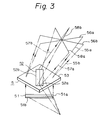
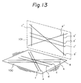
- a scanning window 100 (corresponding to the hologram window 8 of Fig. 6) of a laser beam scanner comprises three layers of holograms stacked one above the other with transparent substrates disposed between the layers. Each hologram layer comprises two parallel strip-form holograms disposed side by side. The holograms of one layer intersect the holograms of the other layers in a central region of the scanning window 100 as seen from above.
- a laser beam scans the six strip-form holograms stacked in three layers in a predetermined order, in accordance with the arrangement of the optical scanning system, and thus traces out six scanning lines (a) to (f), corresponding respectively to the six holograms, on the window 100.
- the scanning beam diffracted by one hologram layer is not diffracted by the other two hologram layers and is emitted from the window in a predetermined direction as a continuous scanning beam.
- the diffracted scanning beams emitted from the window 100 trace out scanning lines (a') to (f') on an imaginary projection plane 101, which lines correspond respectively to the scanning lines (a) to (f) on the window 100.
- the scanning beam (a) diagonally crossing the window 100 is diffracted by the hologram strip and traces a vertical scanning line (a') on the vertical plane 101.
- the scanning pattern it is possible to illuminate and read a bar code above the scanning window by at least one of the scanning beams, for various heights, locations and directions of the movement of the bar code.
Landscapes
- Physics & Mathematics (AREA)
- Engineering & Computer Science (AREA)
- Electromagnetism (AREA)
- Artificial Intelligence (AREA)
- Toxicology (AREA)
- General Health & Medical Sciences (AREA)
- Health & Medical Sciences (AREA)
- Computer Vision & Pattern Recognition (AREA)
- General Physics & Mathematics (AREA)
- Theoretical Computer Science (AREA)
- Mechanical Optical Scanning Systems (AREA)
- Diffracting Gratings Or Hologram Optical Elements (AREA)
- Holo Graphy (AREA)
Applications Claiming Priority (4)
| Application Number | Priority Date | Filing Date | Title |
|---|---|---|---|
| JP23990386 | 1986-10-08 | ||
| JP239903/86 | 1986-10-08 | ||
| JP62107204A JPH0687099B2 (ja) | 1986-10-08 | 1987-04-30 | レ−ザ光走査装置 |
| JP107204/87 | 1987-04-30 |
Publications (3)
| Publication Number | Publication Date |
|---|---|
| EP0263696A2 EP0263696A2 (en) | 1988-04-13 |
| EP0263696A3 EP0263696A3 (en) | 1989-11-02 |
| EP0263696B1 true EP0263696B1 (en) | 1993-02-03 |
Family
ID=26447254
Family Applications (1)
| Application Number | Title | Priority Date | Filing Date |
|---|---|---|---|
| EP87308889A Expired - Lifetime EP0263696B1 (en) | 1986-10-08 | 1987-10-07 | Laser beam scanner |
Country Status (8)
| Country | Link |
|---|---|
| US (1) | US4848862A (ja) |
| EP (1) | EP0263696B1 (ja) |
| JP (1) | JPH0687099B2 (ja) |
| KR (1) | KR900008270B1 (ja) |
| AU (1) | AU592018B2 (ja) |
| CA (1) | CA1298499C (ja) |
| DE (1) | DE3783996T2 (ja) |
| ES (1) | ES2037091T3 (ja) |
Families Citing this family (21)
| Publication number | Priority date | Publication date | Assignee | Title |
|---|---|---|---|---|
| DE68922773T2 (de) * | 1988-03-25 | 1995-09-28 | Fujitsu Ltd | Lichtbündelabtaster. |
| US5231277A (en) * | 1988-12-20 | 1993-07-27 | Fujitsu Limited | Optical scanner using plannar reflecting holograms |
| CA2005862C (en) * | 1988-12-20 | 1995-09-05 | Hirokazu Aritake | Optical scanner using planar reflecting holograms |
| US5237160A (en) * | 1989-08-02 | 1993-08-17 | Ricoh Company, Ltd. | Bar code scanner having hologram |
| US5128520A (en) | 1989-08-11 | 1992-07-07 | Spectra-Physics, Inc. | Scanner with coupon validation |
| US5039183A (en) * | 1989-09-05 | 1991-08-13 | Eastman Kodak Company | Holographic laser scanner |
| DE69028593T2 (de) * | 1989-10-16 | 1997-01-30 | Fujitsu Ltd | Balkencodeleser |
| US5016955A (en) * | 1990-04-19 | 1991-05-21 | Eastman Kodak Company | Holographic laser scanner motor |
| US5286961A (en) * | 1990-05-23 | 1994-02-15 | Tokyo Electric Co., Ltd. | Bar code reader producing two groups of vertical scan lines and two groups of inclined scan lines on a plane normal to the read window |
| JP2716278B2 (ja) * | 1990-05-23 | 1998-02-18 | 株式会社テック | 定置式バーコード読取装置 |
| DE59101271D1 (de) * | 1990-09-19 | 1994-05-05 | Sulzer Chemtech Ag Winterthur | Statischer Mischer mit rohrartigem Gehäuse. |
| US5491328A (en) * | 1991-09-24 | 1996-02-13 | Spectra-Physics Scanning Systems, Inc. | Checkout counter scanner having multiple scanning surfaces |
| US5691830A (en) * | 1991-10-11 | 1997-11-25 | International Business Machines Corporation | Holographic optical system including waveplate and aliasing suppression filter |
| US5475207A (en) * | 1992-07-14 | 1995-12-12 | Spectra-Physics Scanning Systems, Inc. | Multiple plane scanning system for data reading applications |
| US5498862A (en) * | 1993-05-06 | 1996-03-12 | International Computers Limited | Side scanning bar code reader with vertical and horizontal scan patterns |
| JPH08335243A (ja) * | 1995-06-08 | 1996-12-17 | Fujitsu Ltd | バーコードスキャナ |
| US5975417A (en) * | 1997-12-19 | 1999-11-02 | Ncr Corporation | Convertible barcode scanner |
| US7100832B2 (en) * | 2000-04-18 | 2006-09-05 | Metrologic Instruments, Inc. | Bioptical laser scanning system providing 360° of omnidirectional bar code symbol scanning coverage at point of sale station |
| US20030132291A1 (en) * | 2002-01-11 | 2003-07-17 | Metrologic Instruments, Inc. | Point of sale (POS) station having bar code reading system with integrated internet-enabled customer-kiosk terminal |
| US7296748B2 (en) | 2002-01-11 | 2007-11-20 | Metrologic Instruments, Inc. | Bioptical laser scanning system providing 360° of omnidirectional bar code symbol scanning coverage at point of sale station |
| US8523076B2 (en) | 2012-01-10 | 2013-09-03 | Metrologic Instruments, Inc. | Omnidirectional laser scanning bar code symbol reader generating a laser scanning pattern with a highly non-uniform scan density with respect to line orientation |
Family Cites Families (7)
| Publication number | Priority date | Publication date | Assignee | Title |
|---|---|---|---|---|
| US4428643A (en) * | 1981-04-08 | 1984-01-31 | Xerox Corporation | Optical scanning system with wavelength shift correction |
| JPS5880139A (ja) * | 1981-11-04 | 1983-05-14 | Sony Corp | 光学ヘツド |
| JPS59202409A (ja) * | 1983-04-30 | 1984-11-16 | Toppan Printing Co Ltd | 走査装置 |
| JP2532049B2 (ja) * | 1983-06-30 | 1996-09-11 | 富士通株式会社 | 光ビ−ム走査装置 |
| EP0160062A1 (en) * | 1983-10-24 | 1985-11-06 | Applied Holographics Public Limited Company | Holographic backgrounds |
| CH674774A5 (ja) * | 1986-04-03 | 1990-07-13 | Zumbach Electronic Ag | |
| JP3191443B2 (ja) * | 1992-10-14 | 2001-07-23 | 富士通株式会社 | 半導体の表面処理方法 |
-
1987
- 1987-04-30 JP JP62107204A patent/JPH0687099B2/ja not_active Expired - Lifetime
- 1987-10-01 CA CA000548423A patent/CA1298499C/en not_active Expired - Lifetime
- 1987-10-06 AU AU79381/87A patent/AU592018B2/en not_active Ceased
- 1987-10-07 DE DE8787308889T patent/DE3783996T2/de not_active Expired - Fee Related
- 1987-10-07 EP EP87308889A patent/EP0263696B1/en not_active Expired - Lifetime
- 1987-10-07 ES ES198787308889T patent/ES2037091T3/es not_active Expired - Lifetime
- 1987-10-08 US US07/105,571 patent/US4848862A/en not_active Expired - Lifetime
- 1987-10-10 KR KR1019870011234A patent/KR900008270B1/ko not_active IP Right Cessation
Also Published As
| Publication number | Publication date |
|---|---|
| KR880005714A (ko) | 1988-06-30 |
| EP0263696A2 (en) | 1988-04-13 |
| JPS63218914A (ja) | 1988-09-12 |
| AU7938187A (en) | 1988-04-14 |
| DE3783996D1 (de) | 1993-03-18 |
| KR900008270B1 (ko) | 1990-11-10 |
| JPH0687099B2 (ja) | 1994-11-02 |
| ES2037091T3 (es) | 1993-06-16 |
| DE3783996T2 (de) | 1993-06-03 |
| CA1298499C (en) | 1992-04-07 |
| AU592018B2 (en) | 1989-12-21 |
| US4848862A (en) | 1989-07-18 |
| EP0263696A3 (en) | 1989-11-02 |
Similar Documents
| Publication | Publication Date | Title |
|---|---|---|
| EP0263696B1 (en) | Laser beam scanner | |
| US5206491A (en) | Plural beam, plural window multi-direction bar code reading device | |
| KR890002871B1 (ko) | 광속(光速) 주사장치 | |
| KR940010808B1 (ko) | 바 코드 리더(Bar code reader)용 레이저 스캐너 | |
| US6840453B2 (en) | Optical scanning apparatus | |
| JP2789282B2 (ja) | 光学式マーク読取装置 | |
| KR910008421B1 (ko) | 홀로그램 스캐너를 이용한 바코드리더의 바코드 검지방법 및 주사광학계 | |
| US4591236A (en) | Optical scanner with beam directing holograms at window | |
| JPH03156587A (ja) | バーコード読取装置 | |
| EP0396485B1 (en) | Bar code scanner with a large depth of field | |
| US5081364A (en) | Multifocal scanning system | |
| US5231277A (en) | Optical scanner using plannar reflecting holograms | |
| JPS581119A (ja) | ホログラム・スキヤナ | |
| JP2826240B2 (ja) | バーコードリーダ | |
| US5975418A (en) | Bar code scanner with increased number of scanning beams having different directions | |
| US5245170A (en) | Optical scanner using planar reflection holograms | |
| JP2576604B2 (ja) | レーザ光走査装置 | |
| JPS63109590A (ja) | 光学読取装置 | |
| JP2795293B2 (ja) | バーコード読取り装置 | |
| EP0375340A2 (en) | Optical scanner | |
| JPS6238415A (ja) | レ−ザ光走査装置 | |
| JPS63278187A (ja) | 光学読取装置 | |
| JPS6374023A (ja) | ホログラムスキヤナ | |
| JPH04290183A (ja) | バーコード読取り装置 | |
| JPH04283887A (ja) | 読取装置 |
Legal Events
| Date | Code | Title | Description |
|---|---|---|---|
| PUAI | Public reference made under article 153(3) epc to a published international application that has entered the european phase |
Free format text: ORIGINAL CODE: 0009012 |
|
| AK | Designated contracting states |
Kind code of ref document: A2 Designated state(s): DE ES FR GB IT NL SE |
|
| PUAL | Search report despatched |
Free format text: ORIGINAL CODE: 0009013 |
|
| AK | Designated contracting states |
Kind code of ref document: A3 Designated state(s): DE ES FR GB IT NL SE |
|
| 17P | Request for examination filed |
Effective date: 19900119 |
|
| 17Q | First examination report despatched |
Effective date: 19910326 |
|
| ITF | It: translation for a ep patent filed |
Owner name: INTERPATENT ST.TECN. BREV. |
|
| GRAA | (expected) grant |
Free format text: ORIGINAL CODE: 0009210 |
|
| AK | Designated contracting states |
Kind code of ref document: B1 Designated state(s): DE ES FR GB IT NL SE |
|
| REF | Corresponds to: |
Ref document number: 3783996 Country of ref document: DE Date of ref document: 19930318 |
|
| ET | Fr: translation filed | ||
| REG | Reference to a national code |
Ref country code: ES Ref legal event code: FG2A Ref document number: 2037091 Country of ref document: ES Kind code of ref document: T3 |
|
| PLBE | No opposition filed within time limit |
Free format text: ORIGINAL CODE: 0009261 |
|
| STAA | Information on the status of an ep patent application or granted ep patent |
Free format text: STATUS: NO OPPOSITION FILED WITHIN TIME LIMIT |
|
| 26N | No opposition filed | ||
| EAL | Se: european patent in force in sweden |
Ref document number: 87308889.2 |
|
| PGFP | Annual fee paid to national office [announced via postgrant information from national office to epo] |
Ref country code: SE Payment date: 19951017 Year of fee payment: 9 |
|
| PGFP | Annual fee paid to national office [announced via postgrant information from national office to epo] |
Ref country code: NL Payment date: 19951024 Year of fee payment: 9 |
|
| PGFP | Annual fee paid to national office [announced via postgrant information from national office to epo] |
Ref country code: ES Payment date: 19951030 Year of fee payment: 9 |
|
| PG25 | Lapsed in a contracting state [announced via postgrant information from national office to epo] |
Ref country code: SE Effective date: 19961008 Ref country code: ES Free format text: LAPSE BECAUSE OF EXPIRATION OF PROTECTION Effective date: 19961008 |
|
| PG25 | Lapsed in a contracting state [announced via postgrant information from national office to epo] |
Ref country code: NL Effective date: 19970501 |
|
| NLV4 | Nl: lapsed or anulled due to non-payment of the annual fee |
Effective date: 19970501 |
|
| EUG | Se: european patent has lapsed |
Ref document number: 87308889.2 |
|
| REG | Reference to a national code |
Ref country code: ES Ref legal event code: FD2A Effective date: 19990601 |
|
| REG | Reference to a national code |
Ref country code: GB Ref legal event code: IF02 |
|
| PGFP | Annual fee paid to national office [announced via postgrant information from national office to epo] |
Ref country code: GB Payment date: 20021002 Year of fee payment: 16 |
|
| PGFP | Annual fee paid to national office [announced via postgrant information from national office to epo] |
Ref country code: FR Payment date: 20021008 Year of fee payment: 16 |
|
| PGFP | Annual fee paid to national office [announced via postgrant information from national office to epo] |
Ref country code: DE Payment date: 20021011 Year of fee payment: 16 |
|
| PG25 | Lapsed in a contracting state [announced via postgrant information from national office to epo] |
Ref country code: GB Free format text: LAPSE BECAUSE OF NON-PAYMENT OF DUE FEES Effective date: 20031007 |
|
| PG25 | Lapsed in a contracting state [announced via postgrant information from national office to epo] |
Ref country code: DE Free format text: LAPSE BECAUSE OF NON-PAYMENT OF DUE FEES Effective date: 20040501 |
|
| GBPC | Gb: european patent ceased through non-payment of renewal fee |
Effective date: 20031007 |
|
| PG25 | Lapsed in a contracting state [announced via postgrant information from national office to epo] |
Ref country code: FR Free format text: LAPSE BECAUSE OF NON-PAYMENT OF DUE FEES Effective date: 20040630 |
|
| REG | Reference to a national code |
Ref country code: FR Ref legal event code: ST |
|
| PG25 | Lapsed in a contracting state [announced via postgrant information from national office to epo] |
Ref country code: IT Free format text: LAPSE BECAUSE OF NON-PAYMENT OF DUE FEES;WARNING: LAPSES OF ITALIAN PATENTS WITH EFFECTIVE DATE BEFORE 2007 MAY HAVE OCCURRED AT ANY TIME BEFORE 2007. THE CORRECT EFFECTIVE DATE MAY BE DIFFERENT FROM THE ONE RECORDED. Effective date: 20051007 |