EP0263354B1 - Apparatus for the production of foam-backed upholstery, especially motor vehicle upholstery - Google Patents
Apparatus for the production of foam-backed upholstery, especially motor vehicle upholstery Download PDFInfo
- Publication number
- EP0263354B1 EP0263354B1 EP87113867A EP87113867A EP0263354B1 EP 0263354 B1 EP0263354 B1 EP 0263354B1 EP 87113867 A EP87113867 A EP 87113867A EP 87113867 A EP87113867 A EP 87113867A EP 0263354 B1 EP0263354 B1 EP 0263354B1
- Authority
- EP
- European Patent Office
- Prior art keywords
- upholstery
- holder
- friction surface
- thrust bar
- mold cavity
- Prior art date
- Legal status (The legal status is an assumption and is not a legal conclusion. Google has not performed a legal analysis and makes no representation as to the accuracy of the status listed.)
- Expired - Lifetime
Links
Images

Classifications
-
- B—PERFORMING OPERATIONS; TRANSPORTING
- B29—WORKING OF PLASTICS; WORKING OF SUBSTANCES IN A PLASTIC STATE IN GENERAL
- B29C—SHAPING OR JOINING OF PLASTICS; SHAPING OF MATERIAL IN A PLASTIC STATE, NOT OTHERWISE PROVIDED FOR; AFTER-TREATMENT OF THE SHAPED PRODUCTS, e.g. REPAIRING
- B29C51/00—Shaping by thermoforming, i.e. shaping sheets or sheet like preforms after heating, e.g. shaping sheets in matched moulds or by deep-drawing; Apparatus therefor
- B29C51/26—Component parts, details or accessories; Auxiliary operations
-
- B—PERFORMING OPERATIONS; TRANSPORTING
- B29—WORKING OF PLASTICS; WORKING OF SUBSTANCES IN A PLASTIC STATE IN GENERAL
- B29C—SHAPING OR JOINING OF PLASTICS; SHAPING OF MATERIAL IN A PLASTIC STATE, NOT OTHERWISE PROVIDED FOR; AFTER-TREATMENT OF THE SHAPED PRODUCTS, e.g. REPAIRING
- B29C44/00—Shaping by internal pressure generated in the material, e.g. swelling or foaming ; Producing porous or cellular expanded plastics articles
- B29C44/02—Shaping by internal pressure generated in the material, e.g. swelling or foaming ; Producing porous or cellular expanded plastics articles for articles of definite length, i.e. discrete articles
- B29C44/12—Incorporating or moulding on preformed parts, e.g. inserts or reinforcements
- B29C44/14—Incorporating or moulding on preformed parts, e.g. inserts or reinforcements the preformed part being a lining
- B29C44/146—Shaping the lining before foaming
Description
Vorrichtung zum Herstellen von mit hinterschäumten Bezügen versehenen Polstern, insbesondere AutomobilsitzpolsternDevice for producing foam-backed upholstery, in particular automobile seat upholstery
Die Erfindung bezieht sich auf eine Vorrichtung zum Herstellen von mit hinterschäumten Bezügen versehenen Polstern, insbesondere Automobilsitzpolstern, bestehend aus einem Formwerkzeug mit zugeordnetem Mischkopf.The invention relates to a device for producing foam-backed upholstery, in particular automobile seat upholstery, consisting of a molding tool with an associated mixing head.
Man hat schon auf verschiedenste Weise versucht, den Bezugsstoffabschnitt möglichst faltenfrei, beziehungsweise an vorgesehenen Stellen reproduzierbar in unvermeidbare, jedoch geordnete Falten gelegt und überall voll an die Formhohlraumwandung anliegend, im Formhohlraum zu plazieren.Attempts have already been made in various ways to place the cover fabric section as wrinkle-free as possible, or reproducibly in intended places in the inevitable but orderly folds, and to place it fully against the mold cavity wall in the mold cavity.
Es ist allgemein bekannt, hierfür sogenannte Vakuumformwerkzeuge zu verwenden, bei weichen durch in der Formhohlraumwandung vorgesehene Perforationen der Bezugsstoffabschnitt mittels Unterdruck an die Wandung angesaugt wird.It is generally known to use so-called vacuum molding tools for this purpose, in the case of soft perforations provided in the mold cavity wall, the cover material section is sucked onto the wall by means of negative pressure.
In der Regel benutzt man zusätzlich einen Spannrahmen, welcher den zunächst über die untere Formwerkzeughälfte gelegten Bezugsstoffabschnitt mit kontrolliertem Druck auf die den Formhohlraum umgebende Fläche der unteren Formwerk- . zeughälfte drückt. Schließlich ist es auch möglich, einen sogenannten Oberstempel zu benutzen, mit welchem man den Bezugsstoffabschnitt in den Formhohlraum drückt. Meist werden alle drei Maßnahmen gleichzeitig verwendet (DE-OS 27 46 686). Es versteht sich, daß auch jede Maßnahme allein, jedoch mit mäßigerem Erfolg, angewendet werden kann. Auch die Kombination aller drei Maßnahmen zum Zwecke der Optimierung hat dann ihre Grenzen, wenn das zu fertigende Polster kompliziert gestaltet ist und der Formhohlraum ebenfalls eine dementsprechend komplizierte Geometrie, wie beispielsweise Hinterschneidungen, aufweist. An derartig kritischen Stellen ist es nämlich außerordentlich schwierig, den Bezugsstoffabschnitt ohne zuviel direkte manuelle Nachhilfe zum Anliegen an die Formhohlraumwandung zu bekommen. Auch die anschließende Hinterschäumung bietet keine Gewähr, daß die Formhohlraumkontur voll ausgefüllt wird. Unvollständig geformte Polster sind oft nicht nur unansehnlich, sondern auch aus technischen Gründen nicht mehr brauchbar; sie bedeuten Ausschuß.As a rule, an additional clamping frame is used, which initially covers the cover fabric section over the lower mold half with controlled pressure on the surface of the lower mold surrounding the mold cavity. half presses. Finally, it is also possible to use a so-called upper punch, with which the cover fabric section is pressed into the mold cavity. Usually all three measures are used simultaneously (DE-OS 27 46 686). It is understood that each measure can be used alone, but with less success. The combination of all three measures for the purpose of optimization also has its limits if the upholstery to be manufactured is of complicated design and the mold cavity also has a correspondingly complicated geometry, such as undercuts, for example. At such critical points it is extremely difficult to get the upholstery section to lie against the mold cavity wall without too much direct manual tutoring. The subsequent back-foaming does not guarantee that the mold cavity contour will be completely filled. Incompletely shaped cushions are often not only unsightly, but are also no longer usable for technical reasons; they mean committee.
Es besteht die Aufgabe, bei der Herstellung von Polstern der eingangs genannten Art, welche eine komplizierte Form aufweisen, die durch den Formhohlraum entsprechend nachgebildet ist, an den besonders kritischen Stellen des Formhohlraumes, insbesondere an Hinterschneidungen, das Anlegen des Bezugsstoffabschnittes an die Formhohlraumwandung zu verbessern.It is the object in the manufacture of upholstery of the type mentioned, which have a complicated shape, which is simulated by the mold cavity, to improve the application of the cover fabric section to the mold cavity wall at the particularly critical points of the mold cavity, in particular at undercuts .
Gelöst wird diese Aufgabe durch eine über der unteren Formwerkzeughälfte an einer Halterung angeordneten Schubleiste, wobei die untere Formwerkzeughälfte und/oder die Halterung bzw. Schubleiste zueinander bewegbar sind und die Schubleiste der Kontur des Randes des Formhohlraumes angepaßt ist, aber in Schubposition einen die Stärke des Bezugstoffabschnittes berücksichtigenden, jedoch gegenüber dieser Stärke Untermaß aufweisenden Spalt zum Rand des Formhohlraumes beläßt und wobei ihre diesem Rand zugewandte Fläche als Reibfläche ausgebildet ist.This object is achieved by a slide bar arranged above the lower mold half on a holder, the lower mold half and / or the holder or slide bar being movable relative to one another and the slide bar being adapted to the contour of the edge of the mold cavity, but in the push position the strength of the Leaving the fabric section taking into account, but having an undersize compared to this thickness, to the edge of the mold cavity and its surface facing this edge is designed as a friction surface.
Selbstverständlich läßt sich die Schubleiste in besonders vorteilhafter Weise zusammen mit einem Vakuumformwerkzeug, einem Spannrahmen und/oder einem Oberstempel gleichzeitig verwenden. Nichtdestoweniger kann es auch Anwendungsfälle geben, wo die Schubleiste allein ohne die genannten weiteren Hilfen ausreicht, um im Zusammenwirken mit geringer manueller Tätigkeit den Bezugsstoffabschnitt ausreichend gut an der Formhohlraumwandung zu plazieren. Bei der Relativbewegung zwischen Schubleiste und Rand des Formhohlraumes nimmt die Reibfläche den Bezugsstoff mit, so daß nunmehr insbesondere bei Hinterschneidungen die erforderliche Menge vorhanden ist, um sich überall anzulegen. Es versteht sich, daß die Reibfläche und ihre Höhe auf den speziellen Fall abzustimmen sind. Die Reibfläche muß so beschaffen sein, daß sie den Bezugsstoff genügend greift, um ihn schieben zu können. Hierzu gehört auch eine optimale Weite des Spaltes zwischen Rand und Schubleiste bzw. Reibfläche. Die gewählte Höhe der Reibfläche sorgt dafür, daß die benötigte Menge Bezugsstoff nachgeschoben wird. Eine Optimierung dieser Faktoren läßt sich von Fall zu Fall recht einfach durch Versuche ermitteln.Of course, the slide bar can be used in a particularly advantageous manner together with a vacuum molding tool, a tenter and / or an upper punch at the same time. Nevertheless, there can also be applications where the slide bar alone is sufficient without the additional aids mentioned to place the cover fabric section sufficiently well on the mold cavity wall in cooperation with little manual work. During the relative movement between the slide bar and the edge of the mold cavity, the friction surface takes the covering material with it, so that the necessary amount is now available, particularly in the case of undercuts, to fit anywhere. It is understood that the friction surface and its height are to be tailored to the specific case. The friction surface must be such that it grips the cover material enough to be able to push it. This also includes an optimal width of the gap between the edge and the slide bar or friction surface. The selected height of the friction surface ensures that the required amount of covering material is replenished. Optimization of these factors can easily be determined from trial to trial.
Gemäß einer ersten Ausführungsform besteht die Reibfläche aus einer Aufrauhung, beispielsweise in Form einer Rasterung durch Riefen.According to a first embodiment, the friction surface consists of a roughening, for example in the form of a raster by means of scoring.
Eine solche Aufrauhung muß auf die Beschaffenheit der zu beanspruchenden Rückseite des Bezugsstoffabschnittes abgestimmt sein, damit keine Beschädigungen auftreten.Such roughening must be matched to the nature of the back of the cover fabric section to be claimed so that no damage occurs.
Alternativ hierzu besteht die Reibfläche aus einem Elastomerbelag. Auch hier muß die Härte entsprechend der Beschaffenheit der Bezugsstoffrückseite gewählt werden. Es versteht sich, daß der Elastomerbelag zusätzlich Oberflächenkonturen aufweisen kann.Alternatively, the friction surface consists of an elastomer coating. Here too, the hardness must be selected according to the nature of the back of the cover fabric. It goes without saying that the elastomer covering can additionally have surface contours.
Vorzugsweise ist die Schubleiste federnd gelagert.The slide bar is preferably spring-mounted.
Diese Maßnahme ermöglicht es, daß der zwischen der Schubleiste und dem Rand des Formhohlraumes gebildete Spalt durch den darin geführten Bezugsstoffabschnitt völlig ausgefüllt ist, wobei sich die federnde Schubleiste entsprechend gegen den Bezugsstoff anpreßt und auf diese Weise infolge der verstärkten Reibung eine besonders gute Schubkraft ausübt.This measure makes it possible for the gap formed between the push bar and the edge of the mold cavity to be completely filled by the cover fabric section guided therein, the resilient push bar pressing against the cover fabric accordingly and thus exerting a particularly good thrust force due to the increased friction.
Da bei den meisten Vorrichtungen dieser Art die Schubleiste beim Schließen des Formwerkzeuges hinderlich sein würde, ist die Schubleiste vorzugsweise aus dem senkrechten Projektionsbereich des Formwerkzeughohlraumes bzw. des Formwerkzeuges entfernbar.Since in most devices of this type the slide bar would be a hindrance when the mold is closed, the slide bar can preferably be removed from the vertical projection area of the mold cavity or the mold.
Dies geschieht dadurch, daß entweder die untere Formwerkzeughälfte oder, was aus konstruktiven Gründen meist zweckmäßiger ist, die Schubleiste entsprechend verschiebbar gelagert ist.This is done in that either the lower mold half or, which is usually more expedient for design reasons, the slide bar is correspondingly displaceably mounted.
Vorzugsweise ist die Schubleiste an einer als Tragrahmen ausgebildeten Halterung angeordnet.The slide bar is preferably arranged on a holder designed as a supporting frame.
Dies hat den Vorteil, daß man ihn auf Schienen verfahrbar lagern kann. Daß man ihn in Arbeitsposition zweckmäßigerweise fixiert, ist selbstverständlich.This has the advantage that it can be moved on rails. It goes without saying that it is convenient to fix it in the working position.
Wird ein Oberstempel als Halterung verwendet, so läßt sich die Schubleiste vorzugsweise seitlich an diesem Oberstempel anbringen.If an upper punch is used as a holder, the slide bar can preferably be attached laterally to this upper punch.
Auf diese Weise läßt sich die Schubleiste zusammen mit dem Oberstempel aus dem besagten Projektionsbereich entfernen, wobei gegebenenfalls der Oberstempel und damit indirekt die Schubleiste an einem Tragrahmen befestigt sind.In this way, the slide bar can be removed together with the upper ram from said projection area, the upper ram and thus indirectly the slide bar possibly being attached to a supporting frame.
In der Zeichnung ist die neue Vorrichtung rein schematisch in einem Ausführungsbeispiel dargestellt und nachstehend näher erläutert. Es zeigen:
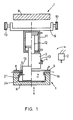
- Fig. 1 die Vorrichtung im Schnitt,
- Fig. 2 eine vergrößerte und detaillierte Darstellung der Anordnung der Schubleiste der Vorrichtung nach Fig. 1 und
- Fig. 3 eine weitere Ausführungsform der Reibfläche der Schubleiste in der Draufsicht.
- 1 shows the device in section,
- Fig. 2 is an enlarged and detailed view of the arrangement of the slide bar of the device according to Fig. 1 and
- Fig. 3 shows another embodiment of the friction surface of the sliding bar in plan view.
In Fig. 1, 2 besteht die Vorrichtung aus einem Vakuumformwerkzeug 1, einem Mischkopf 2, einer als verfahrbarer Oberstempel 3 ausgebildeten Halterung 3 mit Schubleiste 4 sowie einem Spannrahmen 5.1, 2, the device consists of a
Das Vakuumformwerkzeug 1 besteht aus einer unteren Formwerkzeughälfte 6, welche den Formhohlraum 7 enthält und gegen die fix angeordnete, obere Formwerkzeughälfte 8 zum Zwecke des Schließens und Öffnens der Vakuumformwerkzeuges 1 verfahrbar ist. Der Mischkopf 2 ist rein schematisch dargestellt und läßt sich zum Einfüllen eines Polyurethan-Reaktionsgemisches über den Formhohlraum 7 schwenken. Der Oberstempel 3 ist an einem Tragrahmen 9 befestigt, welcher in Schienen 10 aus dem senkrechten Projektionsbereich des Formwerkzeuges 1 bzw. des Formhohlraumes 7 herausfahrbar ist. Der Oberstempel 3 weist einen in einem Zylinder 11 geführten Kolben 12 auf, welcher abwechselnd beidseitig hydraulisch beaufschlagbar ist. In Fig. 1 ist der Oberstempel 3 auf der rechten Seite in oberer Totpunktlage dargestellt, auf der linken Seite in herabgefahrener Stellung. An den Seiten des Oberstempels 3 sind Schubleisten 4 angeordnet. Sie sind mittels Federn 13 am Oberstempel 3 gelagert (siehe Fig. 2) und sind in bezug auf den inneren Rand 14 des Formhohlraumes 7 so eingestellt, daß ein geringer Spalt 15 verbleibt. Hierzu ist die Schubleiste 4 mittels eines Gelenkes 16 an Laschen 17 gelagert, welche in Führungen 18 des Oberstempels 3 ein-und feststellbar gelagert sind (nur eine Lasche und eine Führung sind dargestellt). Beim Herabfahren drückt die Schubleiste 4, welche mit einem höckerartige Konturierungen 19 aufweisenden Elastomerbelag aus Polyurethan als Reibfläche 20 versehen ist, gegen den durch den verbleibenden Spalt 15 geführten Bezugsstoffabschnitt 21 und schiebt inh mit. Ein einstellbarer Anschlagbolzen 22 sorgt dafür, daß die Zusammendrückbarkeit der Feder 13 begrenzt ist, damit eine maximale Breite des Spaltes 15 gewahrt bleibt. Da der nachgeschobene Teil des Bezugsstoffabschnittes 21 momentan nicht gespannt ist, reicht das Vakuum nunmehr wieder aus, um ihn auch in der Hinterschneidung 23 an die Wandung 24 des Formhohlraumes 7 anzusaugen.The
In Fig. 3 ist die Schubleiste 31 mit einer Aufrauhung als Reibfläche 32 versehen, welche sich kreuzende Riefen 33 und dadurch gebildete vierseitige Pyramiden 34 aufweist.In Fig. 3, the
Claims (7)
Applications Claiming Priority (2)
| Application Number | Priority Date | Filing Date | Title |
|---|---|---|---|
| DE3633923A DE3633923C1 (en) | 1986-10-04 | 1986-10-04 | Device for producing upholstered cushions, in particular automobile seat cushions |
| DE3633923 | 1986-10-04 |
Publications (3)
| Publication Number | Publication Date |
|---|---|
| EP0263354A2 EP0263354A2 (en) | 1988-04-13 |
| EP0263354A3 EP0263354A3 (en) | 1989-04-05 |
| EP0263354B1 true EP0263354B1 (en) | 1990-10-31 |
Family
ID=6311112
Family Applications (1)
| Application Number | Title | Priority Date | Filing Date |
|---|---|---|---|
| EP87113867A Expired - Lifetime EP0263354B1 (en) | 1986-10-04 | 1987-09-23 | Apparatus for the production of foam-backed upholstery, especially motor vehicle upholstery |
Country Status (6)
| Country | Link |
|---|---|
| US (1) | US4755120A (en) |
| EP (1) | EP0263354B1 (en) |
| JP (1) | JPS63158210A (en) |
| CA (1) | CA1272874A (en) |
| DE (2) | DE3633923C1 (en) |
| ES (1) | ES2018223B3 (en) |
Families Citing this family (10)
| Publication number | Priority date | Publication date | Assignee | Title |
|---|---|---|---|---|
| JPH047931Y2 (en) * | 1987-09-30 | 1992-02-28 | ||
| DE3739257C1 (en) * | 1987-11-18 | 1988-09-15 | Fritsche Moellmann Gmbh Co Kg | Device for producing upholstered upholstered covers |
| DE3823584A1 (en) * | 1988-07-12 | 1990-01-18 | Grammer Sitzsysteme Gmbh | METHOD FOR PRODUCING A UPHOLSTERY PART |
| DE3823690C1 (en) * | 1988-07-13 | 1989-07-06 | Grammer Sitzsysteme Gmbh, 8450 Amberg, De | |
| US4908084A (en) * | 1988-11-18 | 1990-03-13 | Kenneth Assink | Substrate convering method and apparatus |
| US5593631A (en) * | 1989-06-30 | 1997-01-14 | Sumitomo Chemical Company, Limited | Method for molding resin articles |
| US5018957A (en) * | 1990-05-25 | 1991-05-28 | J R Automation Technologies, Inc. | Hot staking machine |
| US5370516A (en) * | 1993-08-30 | 1994-12-06 | Hoover Universal, Inc. | Apparatus for manufacturing seating components |
| US5871784A (en) * | 1995-06-07 | 1999-02-16 | J. R. Automation Technologies, Inc. | Heat staking apparatus |
| JP2828242B2 (en) * | 1995-11-30 | 1998-11-25 | 大日本印刷株式会社 | Injection molding simultaneous painting apparatus and method |
Family Cites Families (12)
| Publication number | Priority date | Publication date | Assignee | Title |
|---|---|---|---|---|
| US2774410A (en) * | 1953-08-31 | 1956-12-18 | Nat Automotive Fibres Inc | Method and apparatus for tensioning and edge turning the cover material of automobile door laminated panels |
| US3172927A (en) * | 1962-08-22 | 1965-03-09 | Mojonnier Inc Albert | Method and apparatus for molding plastic articles |
| US3531555A (en) * | 1963-03-01 | 1970-09-29 | Haskon Inc | Process for forming foamed containers |
| US3260781A (en) * | 1963-07-02 | 1966-07-12 | Haveg Industries Inc | Process for thermoforming a shrinkresistant foamed polystyrene cup |
| GB1274643A (en) * | 1968-07-04 | 1972-05-17 | Diva Cars Ltd | Improvements relating to motor land vehicles |
| JPS52123762A (en) * | 1976-04-05 | 1977-10-18 | Tachikawa Spring Co | Method of producing seat |
| DE2746686A1 (en) * | 1977-10-18 | 1979-04-19 | Grammer Willibald Fa | Mfr. of a seat cushion complete with case - by lining deep-draw mould with case, applying vacuum and plunger, and filling cavity with foam |
| AT377228B (en) * | 1980-07-24 | 1985-02-25 | Lignotock Verfahrenstech | METHOD AND DEVICE FOR MANUFACTURING MOLDED PARTS FROM LEVEL FLOORED MESH FIBER MATS, PREFERABLY FROM CELLULOSE OR LIGNOCELLULOSE FIBERS PROVIDED WITH BINDERS |
| DE3034973C2 (en) * | 1980-09-17 | 1983-11-24 | Metzeler Schaum Gmbh, 8940 Memmingen | Device for pulling upholstery material into a foam backing mold |
| US4464329A (en) * | 1982-07-01 | 1984-08-07 | Leesona Corporation | Differential pressure synthetic plastic forming machine and method with formed article carrier means |
| DE3319391A1 (en) * | 1983-05-26 | 1984-11-29 | Günter Hans 1000 Berlin Kiss | METHOD FOR MOLDING SPATIAL MOLDED PARTS AND DEVICE FOR IMPLEMENTING THE METHOD |
| US4692199A (en) * | 1985-12-13 | 1987-09-08 | Lear Siegler, Inc. | Method and apparatus for bonding fabric to a foam pad |
-
1986
- 1986-10-04 DE DE3633923A patent/DE3633923C1/en not_active Expired
-
1987
- 1987-09-17 CA CA000547203A patent/CA1272874A/en not_active Expired - Lifetime
- 1987-09-23 DE DE8787113867T patent/DE3765900D1/en not_active Expired - Lifetime
- 1987-09-23 ES ES87113867T patent/ES2018223B3/en not_active Expired - Lifetime
- 1987-09-23 EP EP87113867A patent/EP0263354B1/en not_active Expired - Lifetime
- 1987-09-24 US US07/100,503 patent/US4755120A/en not_active Expired - Fee Related
- 1987-10-02 JP JP62248199A patent/JPS63158210A/en active Pending
Also Published As
| Publication number | Publication date |
|---|---|
| CA1272874A (en) | 1990-08-21 |
| DE3765900D1 (en) | 1990-12-06 |
| DE3633923C1 (en) | 1987-12-10 |
| ES2018223B3 (en) | 1991-04-01 |
| EP0263354A3 (en) | 1989-04-05 |
| EP0263354A2 (en) | 1988-04-13 |
| US4755120A (en) | 1988-07-05 |
| JPS63158210A (en) | 1988-07-01 |
Similar Documents
| Publication | Publication Date | Title |
|---|---|---|
| EP0263354B1 (en) | Apparatus for the production of foam-backed upholstery, especially motor vehicle upholstery | |
| EP0263355B1 (en) | Apparatus for the production of foam-backed upholstery, especially motor vehicle upholstery | |
| EP1287918B1 (en) | Method and device for forming a corner limited on three sides from a flat sheet material | |
| DE102007009705B3 (en) | Press tool assembly for automotive body panels has standard base frame for clamp and standard base frame for press tool | |
| DD252560A5 (en) | METHOD AND DEVICE FOR PULLING METAL PANELS OF LOW STRENGTH | |
| DE3216332C2 (en) | Device for producing a three-dimensionally shaped layered body from a compact plastic layer and a foamed-on foam layer | |
| DE2734999A1 (en) | Tool for joining motor vehicle door panels - has reciprocating slide and wedge ram making inwards curved folded joints | |
| DE102005024378B4 (en) | Method for incremental forming of thin-walled workpieces and device | |
| DE3622971A1 (en) | METHOD AND DEVICE FOR PRODUCING FOAMED UPHOLSTERY WITH A TEXTILE COVER, ESPECIALLY SEAT UPHOLSTERY FOR MOTOR VEHICLES | |
| DE3411023C2 (en) | Device for producing and / or processing laminated workpieces | |
| EP0264003B1 (en) | Method and apparatus for the production of foam-backed upholstery, especially motor vehicle upholstery | |
| DE102004035758B4 (en) | Method and device for producing a decorative preform | |
| DE3208867A1 (en) | METHOD AND DEVICE FOR BENDING LONG-STRETCHED PARTS | |
| EP1056556A1 (en) | Flanging device with pressing and clamping elements | |
| DE1041901B (en) | Device for bending bolsters on the free ends of the resilient wires of switch parts | |
| DE2741684A1 (en) | METHOD AND SHAPE FOR MANUFACTURING AN UPHOLSTERED BODY | |
| DE4413834C1 (en) | Process and apparatus for bending overhangs of a lamination around an edge region of a workpiece | |
| DE681196C (en) | Method and device for pressing large, irregularly shaped sheet metal parts, e.g. Mudguards for cars | |
| EP3378956A1 (en) | Method and device for manufacturing a leather-covered head-rest recess | |
| EP0308771A1 (en) | Method and vacuum-forming die for producing cushions with a backfoamed cover | |
| EP3548244A1 (en) | Device and method for processing a cover, assembly for a vehicle roof, and vehicle roof for a motor vehicle | |
| DE19949576A1 (en) | Mold for producing coated plastic injection molding, especially automobile fitting has sliding coating holder mounted on mold ram and moved by mold die | |
| DE102012204093A1 (en) | Edge folding device for folding end portion of upholstery material used in e.g. furniture, has folding bars that are provided with edge segments which are provided with recess for defined formation of pleat of upholstery material | |
| DE2408883C3 (en) | Device for removing protruding burrs, weld beads or the like | |
| DE1527336C (en) | Device for enforcing and bending profiles |
Legal Events
| Date | Code | Title | Description |
|---|---|---|---|
| PUAI | Public reference made under article 153(3) epc to a published international application that has entered the european phase |
Free format text: ORIGINAL CODE: 0009012 |
|
| 17P | Request for examination filed |
Effective date: 19870923 |
|
| AK | Designated contracting states |
Kind code of ref document: A2 Designated state(s): BE DE ES FR GB IT NL SE |
|
| PUAL | Search report despatched |
Free format text: ORIGINAL CODE: 0009013 |
|
| AK | Designated contracting states |
Kind code of ref document: A3 Designated state(s): BE DE ES FR GB IT NL SE |
|
| 17Q | First examination report despatched |
Effective date: 19900327 |
|
| GRAA | (expected) grant |
Free format text: ORIGINAL CODE: 0009210 |
|
| AK | Designated contracting states |
Kind code of ref document: B1 Designated state(s): BE DE ES FR GB IT NL SE |
|
| REF | Corresponds to: |
Ref document number: 3765900 Country of ref document: DE Date of ref document: 19901206 |
|
| ET | Fr: translation filed | ||
| ITF | It: translation for a ep patent filed |
Owner name: SOCIETA' ITALIANA BREVETTI S.P.A. |
|
| GBT | Gb: translation of ep patent filed (gb section 77(6)(a)/1977) | ||
| PGFP | Annual fee paid to national office [announced via postgrant information from national office to epo] |
Ref country code: ES Payment date: 19910430 Year of fee payment: 5 |
|
| PGFP | Annual fee paid to national office [announced via postgrant information from national office to epo] |
Ref country code: DE Payment date: 19910820 Year of fee payment: 5 |
|
| PLBE | No opposition filed within time limit |
Free format text: ORIGINAL CODE: 0009261 |
|
| STAA | Information on the status of an ep patent application or granted ep patent |
Free format text: STATUS: NO OPPOSITION FILED WITHIN TIME LIMIT |
|
| PGFP | Annual fee paid to national office [announced via postgrant information from national office to epo] |
Ref country code: SE Payment date: 19910909 Year of fee payment: 5 |
|
| PGFP | Annual fee paid to national office [announced via postgrant information from national office to epo] |
Ref country code: FR Payment date: 19910910 Year of fee payment: 5 |
|
| PGFP | Annual fee paid to national office [announced via postgrant information from national office to epo] |
Ref country code: GB Payment date: 19910913 Year of fee payment: 5 |
|
| PGFP | Annual fee paid to national office [announced via postgrant information from national office to epo] |
Ref country code: BE Payment date: 19910925 Year of fee payment: 5 |
|
| ITTA | It: last paid annual fee | ||
| 26N | No opposition filed | ||
| PG25 | Lapsed in a contracting state [announced via postgrant information from national office to epo] |
Ref country code: GB Effective date: 19920923 |
|
| PG25 | Lapsed in a contracting state [announced via postgrant information from national office to epo] |
Ref country code: SE Effective date: 19920924 Ref country code: ES Free format text: LAPSE BECAUSE OF THE APPLICANT RENOUNCES Effective date: 19920924 |
|
| PG25 | Lapsed in a contracting state [announced via postgrant information from national office to epo] |
Ref country code: BE Effective date: 19920930 |
|
| PGFP | Annual fee paid to national office [announced via postgrant information from national office to epo] |
Ref country code: NL Payment date: 19920930 Year of fee payment: 6 |
|
| BERE | Be: lapsed |
Owner name: FRITSCHE-MOLLMANN G.M.B.H. & CO. K.G. Effective date: 19920930 Owner name: BAYER A.G. Effective date: 19920930 |
|
| PG25 | Lapsed in a contracting state [announced via postgrant information from national office to epo] |
Ref country code: NL Effective date: 19930401 |
|
| NLV4 | Nl: lapsed or anulled due to non-payment of the annual fee | ||
| GBPC | Gb: european patent ceased through non-payment of renewal fee |
Effective date: 19920923 |
|
| PG25 | Lapsed in a contracting state [announced via postgrant information from national office to epo] |
Ref country code: FR Effective date: 19930528 |
|
| PG25 | Lapsed in a contracting state [announced via postgrant information from national office to epo] |
Ref country code: DE Effective date: 19930602 |
|
| REG | Reference to a national code |
Ref country code: FR Ref legal event code: ST |
|
| EUG | Se: european patent has lapsed |
Ref document number: 87113867.3 Effective date: 19930406 |
|
| REG | Reference to a national code |
Ref country code: ES Ref legal event code: FD2A Effective date: 19991007 |
|
| PG25 | Lapsed in a contracting state [announced via postgrant information from national office to epo] |
Ref country code: IT Free format text: LAPSE BECAUSE OF NON-PAYMENT OF DUE FEES;WARNING: LAPSES OF ITALIAN PATENTS WITH EFFECTIVE DATE BEFORE 2007 MAY HAVE OCCURRED AT ANY TIME BEFORE 2007. THE CORRECT EFFECTIVE DATE MAY BE DIFFERENT FROM THE ONE RECORDED. Effective date: 20050923 |