EP0263042A1 - Sealing system between a spindle and valve housing, and extractable cup therefor - Google Patents
Sealing system between a spindle and valve housing, and extractable cup therefor Download PDFInfo
- Publication number
- EP0263042A1 EP0263042A1 EP87420248A EP87420248A EP0263042A1 EP 0263042 A1 EP0263042 A1 EP 0263042A1 EP 87420248 A EP87420248 A EP 87420248A EP 87420248 A EP87420248 A EP 87420248A EP 0263042 A1 EP0263042 A1 EP 0263042A1
- Authority
- EP
- European Patent Office
- Prior art keywords
- annular
- sleeve
- sealing
- extraction
- diameter
- Prior art date
- Legal status (The legal status is an assumption and is not a legal conclusion. Google has not performed a legal analysis and makes no representation as to the accuracy of the status listed.)
- Granted
Links
- 238000007789 sealing Methods 0.000 title claims abstract description 72
- 238000000605 extraction Methods 0.000 claims abstract description 81
- 125000006850 spacer group Chemical group 0.000 claims abstract description 10
- 230000000284 resting effect Effects 0.000 claims abstract description 4
- OKTJSMMVPCPJKN-UHFFFAOYSA-N Carbon Chemical compound [C] OKTJSMMVPCPJKN-UHFFFAOYSA-N 0.000 claims description 13
- 229910002804 graphite Inorganic materials 0.000 claims description 13
- 239000010439 graphite Substances 0.000 claims description 13
- 230000006835 compression Effects 0.000 claims description 10
- 238000007906 compression Methods 0.000 claims description 10
- 238000001125 extrusion Methods 0.000 claims description 9
- 210000004907 gland Anatomy 0.000 claims description 7
- 229910000831 Steel Inorganic materials 0.000 description 3
- 238000012423 maintenance Methods 0.000 description 3
- 239000002184 metal Substances 0.000 description 3
- 229910052751 metal Inorganic materials 0.000 description 3
- 239000010959 steel Substances 0.000 description 3
- 229910000906 Bronze Inorganic materials 0.000 description 2
- 239000010974 bronze Substances 0.000 description 2
- KUNSUQLRTQLHQQ-UHFFFAOYSA-N copper tin Chemical compound [Cu].[Sn] KUNSUQLRTQLHQQ-UHFFFAOYSA-N 0.000 description 2
- 229920001971 elastomer Polymers 0.000 description 2
- 239000012530 fluid Substances 0.000 description 2
- 238000009434 installation Methods 0.000 description 2
- 239000000463 material Substances 0.000 description 2
- 238000000034 method Methods 0.000 description 2
- 230000003449 preventive effect Effects 0.000 description 2
- 239000010935 stainless steel Substances 0.000 description 2
- 229910001220 stainless steel Inorganic materials 0.000 description 2
- 208000031968 Cadaver Diseases 0.000 description 1
- 229910001018 Cast iron Inorganic materials 0.000 description 1
- 235000008612 Gnetum gnemon Nutrition 0.000 description 1
- 240000000018 Gnetum gnemon Species 0.000 description 1
- 229920000297 Rayon Polymers 0.000 description 1
- 229910045601 alloy Inorganic materials 0.000 description 1
- 239000000956 alloy Substances 0.000 description 1
- 230000015556 catabolic process Effects 0.000 description 1
- 230000000295 complement effect Effects 0.000 description 1
- 238000006731 degradation reaction Methods 0.000 description 1
- 238000005553 drilling Methods 0.000 description 1
- 230000000694 effects Effects 0.000 description 1
- 239000000806 elastomer Substances 0.000 description 1
- 238000002347 injection Methods 0.000 description 1
- 239000007924 injection Substances 0.000 description 1
- 238000007689 inspection Methods 0.000 description 1
- 239000002964 rayon Substances 0.000 description 1
- 238000004381 surface treatment Methods 0.000 description 1
- 230000008961 swelling Effects 0.000 description 1
- 230000009897 systematic effect Effects 0.000 description 1
- XLYOFNOQVPJJNP-UHFFFAOYSA-N water Substances O XLYOFNOQVPJJNP-UHFFFAOYSA-N 0.000 description 1
Images


Classifications
-
- F—MECHANICAL ENGINEERING; LIGHTING; HEATING; WEAPONS; BLASTING
- F16—ENGINEERING ELEMENTS AND UNITS; GENERAL MEASURES FOR PRODUCING AND MAINTAINING EFFECTIVE FUNCTIONING OF MACHINES OR INSTALLATIONS; THERMAL INSULATION IN GENERAL
- F16K—VALVES; TAPS; COCKS; ACTUATING-FLOATS; DEVICES FOR VENTING OR AERATING
- F16K41/00—Spindle sealings
- F16K41/02—Spindle sealings with stuffing-box ; Sealing rings
-
- F—MECHANICAL ENGINEERING; LIGHTING; HEATING; WEAPONS; BLASTING
- F16—ENGINEERING ELEMENTS AND UNITS; GENERAL MEASURES FOR PRODUCING AND MAINTAINING EFFECTIVE FUNCTIONING OF MACHINES OR INSTALLATIONS; THERMAL INSULATION IN GENERAL
- F16J—PISTONS; CYLINDERS; SEALINGS
- F16J15/00—Sealings
- F16J15/16—Sealings between relatively-moving surfaces
- F16J15/18—Sealings between relatively-moving surfaces with stuffing-boxes for elastic or plastic packings
- F16J15/189—Means for facilitating the removal of the packing
Definitions
- the present invention relates to a sealing system between the operating rod or axis of a valve or a tap and the body of this valve or tap, for uses at temperatures which can range from -245 ° C. to 1050 ° C, with pressures in the pipe or the sealed cavity typically ranging from 0.1 Pa to 40 MPa.
- valve stem and valve body
- casing gland devices include compressible seals or seals, which are housed in the annular chamber which define between them for this purpose the stem and the valve body, and means for axially clamping the seals comprising a support piece or gland engaging in the annular chamber to compress them.
- the quality and stacking height of the seals as well as their compression ratio in service vary with the conditions of use: temperature, pressure, nature of the sealed fluid, sealing requirements.
- types of seals used mention may be made of asbestos-graphite seals, and rings of molded and compressed expanded graphite.
- the subject of the invention is a sealing system between a circular cylindrical rod or operating rod and a valve or tap body defining between them, as is known, an annular chamber ending in a bottom, system comprising as it is known one or more compressible annular seals and a means of axial compression of these seals.
- the compressible sealing ring or rings inserted in the socket essentially ensure, after axial tightening which causes them to be crushed with lateral swelling, the seal between the valve stem and the internal surface of the lateral wall of the sleeve, this internal surface being typically cylindrical of revolution at least over the entire stacking height of the annular sealing means.
- the upper end portion or "upper end" of the side wall of the sleeve leaves free passage for the introduction of the annular sealing means in the sleeve, it carries attachment means or means for extracting the socket after use which are necessarily associated with an appropriate external extraction means.
- This upper end of the side wall of the sleeve is either continuous circular like the rest of the side wall, or discontinuous in the form of lugs carrying the extraction means.
- the bottom of the annular chamber is either flat or inclined at less than 60 °.
- a shaped spacer is preferably used to obtain a flat bearing face.
- the annular seal or lower seal ensuring the seal between the underside of the bottom of the bushing and the bottom or the spacer of the bottom of the annular chamber then typically takes two forms: - Either a flat compressible seal, for example made of elastomer or asbestos-rubber, the underside of the sleeve being flat; or, preferably, a conventional O-ring or an annular seal in compressed expanded graphite, the underside of the annular bottom of the sleeve having a groove or groove in which is embedded in the seal.
- This preferred arrangement allows the correct centering of the seal, and also the adjustment in advance of the level of tightness thanks to the choice of the quality of the seal and of its additional thickness relative to the groove, the compression rate being that of the metal contact. -metal.
- the inner edge of its annular bottom has a clearance with respect to this stem typically between 0.1 and 1 mm at the radius.
- this play is a little strong, for example greater than 0.3 mm in radius in the case of graphite rings, it is highly desirable to place in the sleeve two non-compressible annular rings or washers, respectively placed below and above the stacked ring or sealing rings.
- anti-extrusion rings have a clearance with respect to the valve stem less than or equal to 0.15 mm in radius, and a small clearance and preferably less than 0.2 mm in diameter with respect to to the inner side surface of the socket.
- sealing rings in molded and compressed expanded graphite with a specific mass of between 1.4 and 1.9 g / cm3 thus form, in combination with two anti-extrusion rings, annular sealing means which are particularly well suited to sealing system of the invention.
- the socket is usually made of metal or alloy compatible with the fluid to be sealed, for example in the same material as the valve body.
- the existing axial clamping means comprise a gland whose annular bearing part can engage in the annular chamber but not inside the extractable bush
- these clamping means are completed by an intermediate compression ring of diameter inner diameter greater than the valve stem and outer diameter less than the diameter of the cylindrical inner surface of the sleeve. It can be noted that, when this compression ring has small clearances relative to the rod and relative to the interior of the sleeve, it can possibly replace the anti-extrusion ring situated above the stacked sealing ring or rings .
- the extraction or attachment means carried by the top of this sleeve are necessarily associated with an appropriate external extraction means.
- the extraction means carried by the upper end of the sleeve also constituting the end of its side wall, for example, taking into account in particular for their choice of the possibilities of realization and the mechanical strength necessary for the extraction : - at least 2 radial holes, blind or through, the external extraction means comprising hooks engaging in these holes, particularly when the thickness is small; one or more threaded holes in the thickness, of longitudinal axis, the external extraction means then comprising one or more threaded rods screwing into this or these threaded holes, - an internal thread from the top of the sleeve, the external extraction means comprising a hollow inner dameter tube greater than the diameter of the valve stem, at least the end portion of which is threaded and screws into said internal thread from the top of the sleeve.
- the socket of the invention may also have, in the case where the compression means leaves the corresponding clearance, an upper end projecting from the annular chamber.
- This new arrangement can allow a simpler extraction, the extraction means carried by the top of the sleeve then being its end which protrudes, possibly provided with the hooking means described above, and the external extraction means being any suitable means. , including extraction by hand or with one of the external means already mentioned.
- An external extraction means particularly suitable for sockets carrying at their upper end an internal extraction thread has been developed, it allows a perfectly axial extraction and therefore better preserves the lateral surfaces of the annular chamber and of the rod. valve, and also the state of the annular sealing means.
- This sleeve has a side wall whose inner surface is at least partially circular cylindrical and an annular bottom whose circular inner edge has a diameter at least 0.2 mm greater than the diameter of the valve stem, the underside of the bottom of this bushing carrying a circular groove of U-shaped cross section, and it further comprises extraction means carried by the upper end of the bushing, these extraction means forming part of the group consisting of: internal thread, at minus 2 radial holes, at least one threaded hole in the thickness.
- the sleeve is made up of several removable parts, namely at least 2 adjoining semi-annular cylindrical parts, each comprising an annular bottom portion and extraction means, and an extractable annular bottom on which these cylindrical parts are supported and which carries under its lower face a groove in which the annular seal is embedded in the general case, and on its upper face extraction means, for example threaded holes;
- the annular sealing means possibly comprise compressible sealing rings and segmented into several contiguous parts, the junctions being preferably offset with respect to the junctions of the lateral cylindrical parts of the sleeve.
- the extractable annular bottom preferably has a central opening well adjusted relative to the valve stem, thus having a diameter less than or equal to the diameter of this rod increased by 0.3 mm. And to have a good seal given the junctions between the annular bottom portions of the cylindrical parts, it is important that the upper surface of the extractable bottom define with the rod an annular housing in which the portions of compressible sealing rings are inserted. .
- portions of lower rings typically 2 portions of contiguous rings made of molded and compressed expanded graphite, which rest on the portions of the annular bottom and include annular central portions in excess thickness, these parts placed through the joint planes between the annular bottom portions of the sleeve and the bottom annular extractable and applying in the annular housing thus formed between the extractable bottom and the valve stem.
- this extractable annular bottom can be extracted for inspection and / or replacement of the annular seal less often than the cylindrical parts carrying the parts of sealing rings, which is very advantageous in practice.
- the means for extracting the sleeve and the external extraction means can be kept in principle.
- the removable sleeve comprises 2 semicircular contiguous cylindrical parts
- extraction by thread and threaded tube will be possible, with on the one hand threaded parts on these contiguous parts carrying out by internal thread extraction socket, and with on the other hand a threaded tube reconstituted from 2 longitudinal parts and an extraction part (nut + support) also in 2 reconstituted parts.
- FIGS. 2a and 2c correspond to the example of sealing system described below, usable with valves for pipes containing steam superheated at about 10 MPa -200 ° C.
- the sealing device (1) is associated with a valve stem (2) of diameter 30.0 mm and with a valve body (3) defining with the stem (2) an annular chamber (4) 46.0 mm in diameter, 84 mm deep, and ending in a flat bottom (5) pierced with an orifice (6) for passage of the rod (2), orifice (6) with the same axis of symmetry of revolution as the cylindrical lateral surface (7) of the chamber (4) and of diameter 31.0 mm.
- the extractable sleeve (8) is made of AISI 316L stainless steel, with a total height of 64 mm and an external diameter of 45.9 mm, with a smooth and cylindrical external lateral surface (9) circular over this entire height. It has an annular bottom (10) of total thickness 6 mm, the inner edge (11) or edge of its orifice (12) for passage of the rod, has a diameter of 31 mm. Above this bottom (10), the inner surface (13) of the side wall (14) of the sleeve (8) is circular cylindrical and of diameter 40.0 mm on a height of 51 mm, the portion of upper end (15) of the sleeve comprising (FIG. 2b), above a chamfer (16) intended to facilitate the introduction of the annular sealing means (17), an internally threaded part (18) M 42, 5 mm x 1.5 mm pitch over a height of 6 mm.
- the annular sealing means (17) inserted in the sleeve (8) include 6 rings (19) FARGRAF (registered trademark of the company CEFILAC) in expanded graphite, molded and compressed each with an internal diameter of 30 mm X external diameter 40 mm x thickness 7.5 mm and specific mass 1.6 g / cm3, the stacking of these rings (19) being framed by 2 anti-extrusion rings (20) placed respectively below and above this stacking, each having an internal diameter of 30.2 mm x outside diameter 39.95 mm x thickness 2 mm, in steel with anti-friction surface treatment allowing occasional friction with the valve stem (2) without hurting this stem (2).
- FARGRAF registered trademark of the company CEFILAC
- the underside (21) of the bottom (10) of the sleeve has a circular groove (22) of the same axis of symmetry of revolution with dimensions of internal diameter 34 mm x external diameter 42 mm x depth 3.2 mm, of cross section U-shaped, that is to say with a flat bottom (23) and a lateral surface perpendicular to this bottom.
- the external tightness of the sleeve (2) ensured by a lower seal (24)
- ORIGRAF registered trademark of CEFILAC
- This seal (24) is embedded in the groove (22) and the sealing in service is obtained by axial tightening until contact with the face (21) of the bottom (10) of the sleeve (8) with the flat bottom ( 5) of the annular chamber (4).
- the axial clamping means compressing all the sealing rings (19,24) comprise a conventional gland (25) of bearing portion (26) with an internal diameter of 31 mm and an external diameter of 45.8 mm, coming from the prior device and not entering the sleeve (8), and an intermediate compression ring (27) of inside and outside diameters 31 and 39.8 mm and height 20 mm.
- Figures 2a and 2c respectively represent, apart from this particular example, extraction means carried by the top of other sockets according to the invention, namely: holes radial (28) ( Figure 2a), and holes (29) threaded through the thickness ( Figure 2c).
- the external extraction means (30) used to disassemble the device d sealing (1) comprises only two parts (31) and (32): - a hollow bronze tube (31) material not injuring the seals, with an internal diameter of 32 mm, externally threaded M 42.5 mm x pitch 1.5 mm over its entire length of 220 mm except the chamfers of extremities; an extraction piece (32) made of stainless steel, with an outside diameter of 75 mm and a total height of 76 mm, comprising, from its lower support face (33), an axial internal housing (34) with a diameter of 46 mm and of height 66 mm, and at its upper part a laterally machined portion in the form of a hexagon (35) of 60 mm on flats x height 10 mm with a threaded opening M 42.5 mm x pitch 1.5 mm passing through the upper wall (36) of the housing (34), here coincid
- the extraction of the sealing device (1) is carried out as follows: the threaded tube (31) is screwed into the sleeve (8) until it is locked, then the extraction part (32) is lowered by screwing this part on the threaded tube (31) until contact with the valve body (3). Then, having immobilized the threaded tube (31) in rotation either manually or using a key, the tube (31) carrying at its upper end a hexagon machined in its mass of 36 mm on plates x height 8 mm, we continue to screw the extraction part (32) on the tube (31) using its hexagon (35) and a wrench. The threaded tube (31) is thus mounted on which the extractable sleeve (8) is hung, and screwing is continued until the top of this sleeve (8) stops on the top (37) of the interior housing (34). .
- FIG. 4 schematically represents a sealing device, the installation and extraction of which can be carried out without the drive end of the valve stem (2) being released.
- the sleeve (80) is composed of 2 contiguous semi-cylindrical parts (81), each comprising a cylindrical side wall (140) and an annular bottom portion (100) having a clearance of several mm relative to the valve stem (2) , and a complementary annular bottom (101), extractable by means of threaded rods screwed into 2 threaded holes (102) carried by its upper face (103).
- This extractable bottom (101) has under its lower face (21) a lower seal (24) made of molded and compressed expanded graphite, sealing the bottom (5) of the annular chamber (4).
- the bottom (101) has a central annular zone (104) of lesser thickness, the corresponding hollow surface (105) defining with the valve stem (2) an annular housing (106).
- the central orifice (107) of this bottom has a small clearance relative to the valve stem (2), the surface (105) then having an anti-extrusion role.
- the following practical example can be given relating to a valve stem (2) of diameter 30.0 mm and to an annular chamber of diameter 46.0 mm as in the previous examples, without going back over the means of extraction which are not shown: - the extractable bottom (101), in steel with a treatment of anti-friction surface of the surfaces which can rub on the valve stem (2), has a central opening (107) of 30.2 mm in diameter, a total thickness of 10 mm and a central annular zone of thickness 6 mm and outer diameter 35 mm. Its outside diameter is 45.95 mm.
- Its lower face (21) has the same groove or groove (22) as previously, with the same lower seal (24) embedded in this groove (22); - the semi-cylindrical parts (81) have a thickness of 3 mm, both for their side walls (140) and for their annular bottom portions (100), and the internal diameter of these contiguous annular portions (100) is 35 mm ; the annular sealing means, each segmented into two contiguous parts, include: .
- the sealing system of the invention can be used with all types of taps or valves allowing its installation, usually within the limits already indicated at the beginning of this description.
Landscapes
- General Engineering & Computer Science (AREA)
- Engineering & Computer Science (AREA)
- Mechanical Engineering (AREA)
- Details Of Valves (AREA)
- Lift Valve (AREA)
- Containers And Packaging Bodies Having A Special Means To Remove Contents (AREA)
- Nozzles (AREA)
- Other Liquid Machine Or Engine Such As Wave Power Use (AREA)
- Purses, Travelling Bags, Baskets, Or Suitcases (AREA)
- Load-Engaging Elements For Cranes (AREA)
- Multiple-Way Valves (AREA)
- Closures For Containers (AREA)
- Prostheses (AREA)
Abstract
Description
La présente invention concerne un système d'étanchéité entre la tige ou axe de manoeuvre d'une vanne ou d'un robinet et le corps de cette vanne ou de ce robinet, pour des utilisations à des températures pouvant aller de -245°C à 1050°C, avec des pressions dans la tuyauterie ou la cavité étanche allant elles-même typiquement de 0,1 Pa à 40 MPa.The present invention relates to a sealing system between the operating rod or axis of a valve or a tap and the body of this valve or tap, for uses at temperatures which can range from -245 ° C. to 1050 ° C, with pressures in the pipe or the sealed cavity typically ranging from 0.1 Pa to 40 MPa.
Les systèmes d'étanchéité connus entre tige de manoeuvre ou "tige de vanne" et corps de vanne, appelés couramment "dispositifs presse-étoupe" comportent des garnitures ou joints d'étanchéité compressibles, venant se loger dans la chambre annulaire que définissent entre eux à cet effet la tige et le corps de vanne, et des moyens de serrage axial des joints comprenant une pièce d'appui ou fouloir s'engageant dans la chambre annulaire pour les comprimer. La qualité et la hauteur d'empilage des joints d'étanchéité ainsi que leur taux de compression en service varient avec les conditions d'utilisation: température, pression, nature du fluide étanché, exigences d'étanchéité. Parmi les types de joints utilisés, on peut citer des garnitures amiante-graphite, et des bagues en graphite expansé moulé et comprimé.
Le problème de démontage du dispositif presse-étoupe avec extraction des joints d'étanchéité se pose soit lorsqu'il y a fuite ou dégradation de l'étanchéité, soit pour l'entretien préventif. Ainsi, dans les centrales productrices d'électricité et spécialement dans les centrale nucléaires, un entretien préventif est fait assez fréquemment, par exemple tous les deux ans, pour changes les pièces d'usure à savoir des joints et des pièces d'operculage.The known sealing systems between operating rod or "valve stem" and valve body, commonly called "cable gland devices" include compressible seals or seals, which are housed in the annular chamber which define between them for this purpose the stem and the valve body, and means for axially clamping the seals comprising a support piece or gland engaging in the annular chamber to compress them. The quality and stacking height of the seals as well as their compression ratio in service vary with the conditions of use: temperature, pressure, nature of the sealed fluid, sealing requirements. Among the types of seals used, mention may be made of asbestos-graphite seals, and rings of molded and compressed expanded graphite.
The problem of dismantling the cable gland device with extraction of the seals arises either when there is leakage or degradation of the seal, or for preventive maintenance. Thus, in power plants and especially in nuclear power plants, preventive maintenance is done quite frequently, for example every two years, to change the wearing parts, namely seals and lidding parts.
On constate alors que les joints usagés collent aux surfaces latérales de la chambre où ils sont insérés, et on peut citer deux méthodes utilisées pour obtenir un débouchage faute de pouvoir extraire les joints: de façon artisanale, utilisation de tire-bouchons à manche souple, et, dans l'entretien systématique des centrales énergétiques, perçage laser avec injection d'eau sous pression. Ces méthodes sont coûteuses ou consommatrices de temps.We can then see that the used seals stick to the lateral surfaces of the chamber where they are inserted, and we can cite two methods used to obtain an unblocking because we cannot extract the seals: the traditional way, using corkscrews with flexible handles, and, in the systematic maintenance of power plants, laser drilling with injection pressurized water. These methods are expensive or time consuming.
La demanderesse à essayé de parvenir à un mode d'extraction des joints d'étanchéité plus satisfaisant, c'est-à-dire moins coûteux et/ou plus rapide, dans ce cas des "dispositifs presse-étoupe".The Applicant has tried to achieve a more satisfactory mode of extraction of the seals, that is to say less expensive and / or faster, in this case "cable gland devices".
L'invention a pour objet un système d'étanchéité entre une tige cylindrique circulaire ou tige de manoeuvre et un corps de vanne ou de robinet définissant entre eux, comme il est connu, une chambre annulaire se terminant par un fond, système comportant comme il est connu un ou plusieurs joints d'étanchéité annulaires compressibles et un moyen de compression axiale de ces joints.The subject of the invention is a sealing system between a circular cylindrical rod or operating rod and a valve or tap body defining between them, as is known, an annular chamber ending in a bottom, system comprising as it is known one or more compressible annular seals and a means of axial compression of these seals.
Selon l'invention, ce système d'étanchéité, dont les joints d'étanchéité sont facilement extraits après usage, comprend:
- a/ un dispositif d'étanchéité extractible comprenant lui-même:
- a1/ une douille porte-garnitures d'étanchéité extractible s'encastrant dans la chambre annulaire, comportant une paroi latérale dont la surface intérieure est au moins en partie cylindrique et un fond annulaire dont le bord intérieur a un jeu par rapport à la tige qui traverse ce fond d'au moins 0,1 mm au rayon, la surface inférieure de ce fond de la douille s'appliquant sur un joint d'étanchéité annulaire compressible qui s'appuie sur le fond de la chambre annulaire ou sur une entretoise annulaire reposant sur ce fond, et comportant aussi, à l'extrémité haute de sa paroi latérale, des moyens d'extraction ne débordant pas transversalement par rapport à cette paroi latérale.
- a2/ des moyens d'étanchéité annulaires insérés dans la douille, comprenant une ou plusieurs bagues d'étanchéité compressibles;
- a3/ ledit joint d'étanc héité annulaire, disposé entre le fond de la douille et le fond ou ladite entretoise de la chambre annulaire;
- b/ un ou des moyens de serrage axial comprimant à la fois lesdits moyens d'étanchéité, entre ce ou ces moyens de serrage et le fond annulaire de la douille, et ledit joint d'étanchéité annulaire entre la face inférieure du fond de la douille et le fond ou ladite entretoise de la chambre annulaire;
- c/ un moyen d'extraction externe coopérant avec les moyens d'extraction portés par la douille.
- a / an extractable sealing device itself comprising:
- a1 / an extractable seal holder sleeve fitting into the annular chamber, comprising a side wall whose inner surface is at least partially cylindrical and an annular bottom whose inner edge has a clearance with respect to the rod which crosses this bottom by at least 0.1 mm to the radius, the lower surface of this bottom of the socket applying to a compressible annular seal which rests on the bottom of the annular chamber or on an annular spacer resting on this bottom, and also comprising, at the high end of its side wall, extraction means not projecting transversely with respect to this side wall.
- a2 / annular sealing means inserted in the sleeve, comprising one or more compressible sealing rings;
- a3 / said annular ring seal, disposed between the bottom of the sleeve and the bottom or said spacer of the annular chamber;
- b / one or more axial clamping means compressing both said sealing means, between this or these clamping means and the annular bottom of the socket, and said annular seal between the underside of the bottom of the socket and the bottom or said spacer of the annular chamber;
- c / an external extraction means cooperating with the extraction means carried by the sleeve.
La ou les bagues d'étanchéité compressibles insérées dans la douille assurent essentiellement, après serrage axial qui entraîne leur écrasement avec un gonflement latéral, l'étanchéité entre la tige de vanne et la surface intérieure de la paroi latérale de la douille, cette surface intérieure étant typiquement cylindrique de révolution au moins sur toute la hauteur d'empilement des moyens d'étanchéité annulaires. La portion d'extrémité haute ou "extrémité haute" de la paroi latérale de la douille laisse le passage libre pour l'introduction des moyens d'étanchéité annulaires dans la douille, elle porte des moyens d'accrochage ou moyens d'extraction de la douille après usage qui sont nécessairement associés avec un moyen d'extraction externe approprié. Cette extrémité haute de la paroi latérale de la douille est soit circulaire continue comme le reste de la paroi latérale, soit discontinue sous forme de pattes portant les moyens d'extraction.The compressible sealing ring or rings inserted in the socket essentially ensure, after axial tightening which causes them to be crushed with lateral swelling, the seal between the valve stem and the internal surface of the lateral wall of the sleeve, this internal surface being typically cylindrical of revolution at least over the entire stacking height of the annular sealing means. The upper end portion or "upper end" of the side wall of the sleeve leaves free passage for the introduction of the annular sealing means in the sleeve, it carries attachment means or means for extracting the socket after use which are necessarily associated with an appropriate external extraction means. This upper end of the side wall of the sleeve is either continuous circular like the rest of the side wall, or discontinuous in the form of lugs carrying the extraction means.
Le fond de la chambre annulaire est soit plat, soit incliné à moins de 60°. Dans le deuxième cas on utilise de préférence une entretoise de forme pour obtenir une face d'appui plane. Le joint d'étanchéité annulaire ou joint inférieur assurant l'étanchéité entre la face inférieure du fond de la douille et le fond ou l'entretoise du fond de la chambre annulaire se présente alors typiquement sous deux formes:
- soit un joint compressible plat, par exemple en élastomère ou en amiante-caoutchouc, la face inférieure de la douille étant plane;
-soit, de préférence, un joint torique classique ou un joint annulaire en graphite expansé comprimé, la face inférieure du fond annulaire de la douille comportant une gorge ou rainure dans laquelle est encastré dans le joint. Cette disposition préférée permet le bon centrage du joint, et aussi le réglage à l'avance du niveau d'étanchéité grâce au choix de la qualité du joint et de sa surépaisseur par rapport à la gorge, le taux de compression étant celui du contact métal-métal.The bottom of the annular chamber is either flat or inclined at less than 60 °. In the second case, a shaped spacer is preferably used to obtain a flat bearing face. The annular seal or lower seal ensuring the seal between the underside of the bottom of the bushing and the bottom or the spacer of the bottom of the annular chamber then typically takes two forms:
- Either a flat compressible seal, for example made of elastomer or asbestos-rubber, the underside of the sleeve being flat;
or, preferably, a conventional O-ring or an annular seal in compressed expanded graphite, the underside of the annular bottom of the sleeve having a groove or groove in which is embedded in the seal. This preferred arrangement allows the correct centering of the seal, and also the adjustment in advance of the level of tightness thanks to the choice of the quality of the seal and of its additional thickness relative to the groove, the compression rate being that of the metal contact. -metal.
De façon à ne pas blesser la tige de vanne, le bord intérieur de son fond annulaire a un jeu par rapport à cette tige typiquement compris entre 0,1 et 1 mm au rayon. Pour éviter des effets d'extrusion des bagues d'étanchéité lors de la compression, lorsque ce jeu est un peu fort, par exemple supérieur à 0,3 mm au rayon dans le cas de bagues en graphite, il est fortement souhaitable de placer dans la douille deux bagues ou rondelles annulaires non compressibles, disposées respectivement en-dessous et au-dessus de la bague ou des bagues d'étanchéité empilées. Ces bagues ou rondelles non compressibles souvent appelées "bagues antiextrusion" ont un jeu par rapport à la tige de vanne inférieur ou égal à 0,15 mm au rayon, et un jeu faible et de préférence inférieur à 0,2 mm au diamètre par rapport à la surface intérieure latérale de la douille.In order not to injure the valve stem, the inner edge of its annular bottom has a clearance with respect to this stem typically between 0.1 and 1 mm at the radius. To avoid the effects of extrusion of the sealing rings during compression, when this play is a little strong, for example greater than 0.3 mm in radius in the case of graphite rings, it is highly desirable to place in the sleeve two non-compressible annular rings or washers, respectively placed below and above the stacked ring or sealing rings. These non-compressible rings or washers often called "anti-extrusion rings" have a clearance with respect to the valve stem less than or equal to 0.15 mm in radius, and a small clearance and preferably less than 0.2 mm in diameter with respect to to the inner side surface of the socket.
Ce sont typiquement des rondelles plates, en acier avec sur leur bord intérieur une surface traitée anti-friction pour supprimer tout risque de blesser la tige de vanne, ou encore en bronze ou en fonte. Une ou plusieurs bagues d'étanchéité en graphite expansé moulé et comprimé de masse spécifique comprise entre 1,4 et 1,9 g/cm3 forment ainsi, en association avec deux bagues anti-extrusion,des moyens d'étanchéité annulaires particulièrement bien adaptés au système d'étanchéité de l'invention.These are typically flat washers, made of steel with an anti-friction treated surface on their inner edge to eliminate any risk of injuring the valve stem, or in bronze or cast iron. One or more sealing rings in molded and compressed expanded graphite with a specific mass of between 1.4 and 1.9 g / cm3 thus form, in combination with two anti-extrusion rings, annular sealing means which are particularly well suited to sealing system of the invention.
La douille est habituellement en métal ou alliage compatible avec le fluide à étancher, par exemple dans le mêm e matériau que le corps de vanne.The socket is usually made of metal or alloy compatible with the fluid to be sealed, for example in the same material as the valve body.
Quand les moyens de serrage axial existants comportent un fouloir dont la pièce d'appui annulaire peut s'engager dans la chambre annulaire mais pas à l'intérieur de la douille extractible, on complète ces moyens de serrage par une bague de compression intermédiaire de diamètre intérieur supérieur au diamètre de la tige de vanne et de diamètre extérieur inférieur au diamètre de la surface intérieure cylindrique de la douille. On peut remarquer que, lorsque cette bague de compression a des jeux faibles par rapport à la tige et par rapport à l'intérieur de la douille, elle peut éventuellement remplacer la bague antiextrusion située au-dessus de la ou des bagues d'étanchéité empilées.When the existing axial clamping means comprise a gland whose annular bearing part can engage in the annular chamber but not inside the extractable bush, these clamping means are completed by an intermediate compression ring of diameter inner diameter greater than the valve stem and outer diameter less than the diameter of the cylindrical inner surface of the sleeve. It can be noted that, when this compression ring has small clearances relative to the rod and relative to the interior of the sleeve, it can possibly replace the anti-extrusion ring situated above the stacked sealing ring or rings .
Dans le cas habituel où la douille est entièrement contenue dans la chambre annulaire, les moyens d'extraction ou d'accrochage portés par le haut de cette douille sont nécessairement associés à un moyen d'extraction externe approprié. Les moyens d'extraction portés par l'extrémité haute de la douille constituant aussi l'extrémité de sa paroi latérale, sont par exemple, en tenant compte en particulier pour leur choix des possibilités de réalisation et de la résistance mécanique nécessaire pour l'extraction:
- au moins 2 trous radiaux, borgnes ou traversants, le moyen d'extraction externe comportant des crochets s'engageant dans ces trous, particulièrement lorsque l'épaisseur est faible;
- un ou plusieurs trous filetés dans l'épaisseur, d'axe longitudinal, le moyen d'extraction externe comportant alors une ou des tiges filetées se vissant dans ce ou ces trous filetés,
- un filetage intérieur du haut de la douille, le moyen d'extraction externe comportant un tube creux de damètre intérieur supérieur au diamètre de la tige de vanne, dont la portion d'extrémité au moins est filetée et se visse dans ledit filetage intérieur du haut de la douille. Dans le cas où la tige de vanne est démontée avant l'extraction de la douille, ce tube creux peut être remplacé par une barre ou tige portant le même filetage.In the usual case where the sleeve is entirely contained in the annular chamber, the extraction or attachment means carried by the top of this sleeve are necessarily associated with an appropriate external extraction means. The extraction means carried by the upper end of the sleeve also constituting the end of its side wall, for example, taking into account in particular for their choice of the possibilities of realization and the mechanical strength necessary for the extraction :
- at least 2 radial holes, blind or through, the external extraction means comprising hooks engaging in these holes, particularly when the thickness is small;
one or more threaded holes in the thickness, of longitudinal axis, the external extraction means then comprising one or more threaded rods screwing into this or these threaded holes,
- an internal thread from the top of the sleeve, the external extraction means comprising a hollow inner dameter tube greater than the diameter of the valve stem, at least the end portion of which is threaded and screws into said internal thread from the top of the sleeve. In the case where the valve stem is removed before the socket is extracted, this hollow tube can be replaced by a bar or stem with the same thread.
La douille de l'invention peut avoir également, dans le cas où le moyen de compression laisse le dégagement correspondant, une extrémité haute dépassant de la chambre annulaire. Cette disposition nouvelle peut permettre une extraction plus simple, les moyens d'extraction portés par le haut de la douille étant alors son extrémité qui dépasse, éventuellement munie des moyens d'accrochage décrits précédemment, et le moyen d'extraction externe étant tout moyen convenable, y compris l'extraction à la main ou bien avec l'un des moyens externes déjà signalés.The socket of the invention may also have, in the case where the compression means leaves the corresponding clearance, an upper end projecting from the annular chamber. This new arrangement can allow a simpler extraction, the extraction means carried by the top of the sleeve then being its end which protrudes, possibly provided with the hooking means described above, and the external extraction means being any suitable means. , including extraction by hand or with one of the external means already mentioned.
Lorsque le serrage direct du joint inférieur annulaire situé entre le fond de la douille et le fond de la chambre annulaire est nécessaire ou souhaitable, par exemple dans le cas de très fortes pressions à étancher, cette disposition permet aussi d'assurer simplement ce serrage à l'aide d'une bride fixée sur le corps de vanne. Il est possible d'obtenir un tel serrage direct dans le cas d'une douille ne dépassant pas de la chambre annulaire, grâce à une bride usinée avec une ou plusieurs parties en relief, par exemple une virole, qui appuient directement sur la douille, mais cette structure équivalente à la précédente est évidemment plus délicate à réaliser.When direct tightening of the annular lower seal located between the bottom of the sleeve and the bottom of the annular chamber is necessary or desirable, for example in the case of very high pressures to be sealed, this arrangement also makes it possible to simply ensure this tightening at using a flange fixed on the valve body. It is possible to obtain such direct tightening in the case of a socket not exceeding the annular chamber, thanks to a flange machined with one or more raised parts, for example a ferrule, which press directly on the socket, but this structure equivalent to the previous one is obviously more difficult to achieve.
Un moyen d'extraction externe particulièrement adapté aux douilles portant à leur extrémité haute un filetage intérieur d'extraction a été mis au point, il permet une extraction parfaitement axiale et donc de mieux préserver les surfaces latérales de la chambre annulaire et de la tige de vanne, et aussi l'état des moyens d'étanchéité annulaires.An external extraction means particularly suitable for sockets carrying at their upper end an internal extraction thread has been developed, it allows a perfectly axial extraction and therefore better preserves the lateral surfaces of the annular chamber and of the rod. valve, and also the state of the annular sealing means.
Ce moyen d'extraction externe comprend au moins;
- d) un tube creux fileté, de diamètre intérieur supérieur au diamètre de la tige de vanne, se vissant dans le filetage intérieur du haut de la douille, ainsi que dans l'écrou (e);
- e) un écrou d'extraction fileté intérieurement avec le même filetage que celui du haut de la dou ille;
- f) un support d'extraction, permettant le maintien de l'écrou d'extraction, pendant sa rotation, à hauteur au moins égale à la hauteur totale de la douille extractible diminuée de sa hauteur de vissage par le tube fileté.
- d) a hollow threaded tube, with an internal diameter greater than the diameter of the valve stem, screwing into the internal thread of the top of the sleeve, as well as into the nut (e);
- e) an internally threaded extraction nut with the same thread as that of the top of the sleeve;
- f) an extraction support, allowing the extraction nut to be maintained, during its rotation, at a height at least equal to the total height of the extractable bush less its screwing height by the threaded tube.
L'invention a encore pour objet la douille extractible elle-même, utilisée pour réaliser l'étanchéité entre une tige de vanne et un corps de vanne définissant entre eux une chambre annulaire, dans une version préférentielle. Cette douille comporte une paroi latérale dont la surface intérieure est au moins en partie cylindrique circulaire et un fond annulaire dont le bord intérieur circulaire a un diamètre supérieur d'au moins 0,2 mm au diamètre de la tige de vanne, la face inférieure du fond de cette douille portant une gorge circulaire de section droite en U, et elle comporte en outre des moyens d'extraction portés par l'extrémité haute de la douille, ces moyens d'extraction faisant partie du groupe constitué par: filetage intérieur, au moins 2 trous radiaux, au moins un trou fileté dans l'épaisseur.Another subject of the invention is the extractable bushing itself, used for sealing between a valve stem and a valve body defining between them an annular chamber, in a preferred version. This sleeve has a side wall whose inner surface is at least partially circular cylindrical and an annular bottom whose circular inner edge has a diameter at least 0.2 mm greater than the diameter of the valve stem, the underside of the bottom of this bushing carrying a circular groove of U-shaped cross section, and it further comprises extraction means carried by the upper end of the bushing, these extraction means forming part of the group consisting of: internal thread, at minus 2 radial holes, at least one threaded hole in the thickness.
Dans le cas où l'ensemble de commande de la vanne ne peut pas être démonté, l'extraction de la douille étant de ce fait impossible, il y a lieu d'utiliser un dispositif d'étanchéité selon l'invention démontable:
- la douille est composée de plusieurs parties démontables, à savoir au moins 2 parties cylindriques semi-annnulaires jointives comportant chacune une portion de fond annulaire et des moyens d'extraction, et un fond annulaire extractible sur lequel ces parties cylindriques s'appuient et qui porte sous sa face inférieure une gorge dans laquelle s'encastre le joint d'étanchéité annulaire du cas général, et sur sa face supérieure des moyens d'extraction, par exemple des trous filetés;
- les moyens d'étanchéité annulaires comprennent éventuellement des bagues d'étanchéité compressibles et segmentés en plusieurs parties jointives, les jonctions étant de préférence décalées par rapport aux jonctions des parties cylindriques latérales de la douille.In the case where the valve control assembly cannot be dismantled, the extraction of the bushing being therefore impossible, it is necessary to use a removable sealing device according to the invention:
- The sleeve is made up of several removable parts, namely at least 2 adjoining semi-annular cylindrical parts, each comprising an annular bottom portion and extraction means, and an extractable annular bottom on which these cylindrical parts are supported and which carries under its lower face a groove in which the annular seal is embedded in the general case, and on its upper face extraction means, for example threaded holes;
- The annular sealing means possibly comprise compressible sealing rings and segmented into several contiguous parts, the junctions being preferably offset with respect to the junctions of the lateral cylindrical parts of the sleeve.
L'utilisation de bagues anti-extrusion au fond présentant des difficultés de positionnement et étant donc déconseillé, le fond annulaire extractible a de préférence un orifice central bien ajusté par rapport à la tige de vanne, ayant ainsi un diamètre inférieur ou égal au diamètre de cette tige augmenté de 0,3 mm. Et pour avoir une bonne étanchéité compte tenu des jonctions entre portions de fond annulaire des parties cylindriques, il est important que la surface supérieure du fond extractible définisse avec la tige un logement annulaire dans lequel viennent s'insérer les portions de bagues d'étanchéité compressibles. La disposition optimale pour l'étanchéité est alors obtenue avec des portions de bagues inférieures, typiquement 2 portions de bagues jointives en graphite expansé moulé et comprimé, qui s'appuient sur les portions de fond annulaire et comportent des parties centrales annulaires en surépaisseur,ces parties se plaçant au travers des plans de joints entre portions de fond annulaire de la douille et fond annulaire extractible et s'appliquant dans le logement annulaire ainsi formé entre le fond extractible et la tige de vanne.The use of anti-extrusion rings at the bottom presenting positioning difficulties and therefore being inadvisable, the extractable annular bottom preferably has a central opening well adjusted relative to the valve stem, thus having a diameter less than or equal to the diameter of this rod increased by 0.3 mm. And to have a good seal given the junctions between the annular bottom portions of the cylindrical parts, it is important that the upper surface of the extractable bottom define with the rod an annular housing in which the portions of compressible sealing rings are inserted. . The optimal arrangement for sealing is then obtained with portions of lower rings, typically 2 portions of contiguous rings made of molded and compressed expanded graphite, which rest on the portions of the annular bottom and include annular central portions in excess thickness, these parts placed through the joint planes between the annular bottom portions of the sleeve and the bottom annular extractable and applying in the annular housing thus formed between the extractable bottom and the valve stem.
Dans ce dispositif démontable dont le fond est ainsi dédoublé en des fonds jointifs permettant l'extraction des parties de bagues et en un fond annulaire extractible associé à un joint annulaire continu réalisant l'étanchéité sur le fond de la chambre annulaire, ce fond annulaire extractible peut être extrait pour contrôle et/ou remplacement du joint annulaire moins souvent que les parties cylindriques portant les parties de bagues d'étanchéité, ce qui est fort intéressant en pratique.In this removable device, the bottom of which is thus split into joined bottoms allowing the extraction of the ring parts and into an extractable annular bottom associated with a continuous annular seal sealing the bottom of the annular chamber, this extractable annular bottom can be extracted for inspection and / or replacement of the annular seal less often than the cylindrical parts carrying the parts of sealing rings, which is very advantageous in practice.
Dans ce cas du dispositif d'étanchéité démontable, les moyens d'extraction de la douille et les moyens d'extraction externes peuvent être conservés dans leurs principes. Ainsi, dans le cas où la douille démontable comporte 2 parties cylindriques jointives hémicirculaires, l'extraction par filetage et tube fileté sera possible, avec d'une part sur ces parties jointives des parties filetées réalisant par rapprochement un filetage intérieur d'extraction de la douille, et avec d'autre part un tube fileté reconstitué à partir de 2 parties longitudinales et une pièce d'extraction (écrou + support) également en 2 parties reconstituées.In this case of the removable sealing device, the means for extracting the sleeve and the external extraction means can be kept in principle. Thus, in the case where the removable sleeve comprises 2 semicircular contiguous cylindrical parts, extraction by thread and threaded tube will be possible, with on the one hand threaded parts on these contiguous parts carrying out by internal thread extraction socket, and with on the other hand a threaded tube reconstituted from 2 longitudinal parts and an extraction part (nut + support) also in 2 reconstituted parts.
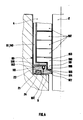
- La figure 1 représente un dispositif d'étanchéité extractible selon l'invention, en coupe par un plan passant par l'axe de la tige de vanne.FIG. 1 represents an extractable sealing device according to the invention, in section through a plane passing through the axis of the valve stem.
- Les figures 2a, 2b, 2c représentent des moyens d'extraction portés par la douille extractible de l'invention.Figures 2a, 2b, 2c show extraction means carried by the extractable bush of the invention.
- La figure 3 représente, en coupe par un plan passant par l'axe de la tige de vanne, le dispositif d'étanchéité surmonté d'un moyen d'extraction externe, à gauche en position initiale vissée, à droite après extraction hors de la chambre annulaire.FIG. 3 represents, in section through a plane passing through the axis of the valve stem, the sealing device surmounted by an external extraction means, on the left in the initial screwed position, right after extraction out of the annular chamber.
- La figure 4 représente un dispositif d'étanchéité extractible démontable selon l'invention, en demi-coupe axiale passant par le plan de jonction des 2 parties cylindriques jointives de la douille.FIG. 4 represents a removable extractable sealing device according to the invention, in axial half-section passing through the junction plane of the 2 contiguous cylindrical parts of the sleeve.
Les figures autres que les figures 2a et 2c correspondent à l'exemple de système d'étanchéité décrit ci-dessous, utilisable avec des vannes pour canalisations contenant de la vapeur d'eau surchauffée à environ 10 MPa -200°C.The figures other than FIGS. 2a and 2c correspond to the example of sealing system described below, usable with valves for pipes containing steam superheated at about 10 MPa -200 ° C.
Le dispositif d'étanchéité (1) selon l'invention est associé à une tige de vanne (2) de diamètre 30,0 mm et à un corps de vanne (3) définissant avec la tige (2) une chambre annulaire (4) de diamètre 46,0 mm, de profondeur 84 mm, et se terminant par un fond plat (5) percé d'un orifice (6) de passage de la tige (2), orifice (6) de même axe de symétrie de révolution que la surface latérale cylindrique (7) de la chambre (4) et de diamètre 31,0 mm.The sealing device (1) according to the invention is associated with a valve stem (2) of diameter 30.0 mm and with a valve body (3) defining with the stem (2) an annular chamber (4) 46.0 mm in diameter, 84 mm deep, and ending in a flat bottom (5) pierced with an orifice (6) for passage of the rod (2), orifice (6) with the same axis of symmetry of revolution as the cylindrical lateral surface (7) of the chamber (4) and of diameter 31.0 mm.
La douille extractibe (8) est an acier inoxydable AISI 316L, de hauteur totale 64 mm et de diamètre extérieur 45,9 mm, avec une surface latérale extérieure (9) lisse et cylindrique circulaire sur toute cette hauteur. Elle comporte un fond annulaire (10) d'épaisseur totale 6 mm dont le bord intérieur (11) ou bord de son orifice (12) de passage de la tige, a un diamètre de 31 mm. Au-dessus de ce fond (10), la surface intérieure (13) de la paroi latérale (14) de la douille (8) est cylindrique circulaire et de diamètre 40,0 mm sur une hauteur de 51 mm, la portion d'extrémité haute (15) de la douille comportant (figure 2b), au-dessus d'un chanfrein (16) destiné à faciliter l'introduction des moyens d'étanchéité annulaires (17), une partie filetée intérieurement (18) M 42,5 mm x pas 1,5 mm sur une hauteur de 6 mm.The extractable sleeve (8) is made of AISI 316L stainless steel, with a total height of 64 mm and an external diameter of 45.9 mm, with a smooth and cylindrical external lateral surface (9) circular over this entire height. It has an annular bottom (10) of total thickness 6 mm, the inner edge (11) or edge of its orifice (12) for passage of the rod, has a diameter of 31 mm. Above this bottom (10), the inner surface (13) of the side wall (14) of the sleeve (8) is circular cylindrical and of diameter 40.0 mm on a height of 51 mm, the portion of upper end (15) of the sleeve comprising (FIG. 2b), above a chamfer (16) intended to facilitate the introduction of the annular sealing means (17), an internally threaded part (18)
Les moyens d'étanchéité annulaires (17) insérés dans la douille (8) (figure 1) comprennent 6 bagues (19) FARGRAF (marque déposée de la société CEFILAC) en graphite expansé,moulé et comprimé chacune de diamètre intérieur 30 mm X diamètre extérieur 40 mm x épaisseur 7,5 mm et de masse spécifique 1,6 g/cm3, l'empilage de ces bagues (19) étant encadré par 2 bagues anti-extrusion (20) placées respectivement au-dessous et au-dessus de cet empilage, chacune étant de diamètre intérieur 30,2 mm x diamètre extérieur 39,95 mm x épaisseur 2 mm, en acier avec traitement de surface anti-friction permettant le frottement occasionnel avec la tige de vanne (2) sans que cela blesse cette tige (2).The annular sealing means (17) inserted in the sleeve (8) (figure 1) include 6 rings (19) FARGRAF (registered trademark of the company CEFILAC) in expanded graphite, molded and compressed each with an internal diameter of 30 mm X external diameter 40 mm x thickness 7.5 mm and specific mass 1.6 g / cm3, the stacking of these rings (19) being framed by 2 anti-extrusion rings (20) placed respectively below and above this stacking, each having an internal diameter of 30.2 mm x outside diameter 39.95 mm x
La face inférieure (21) du fond (10) de la douille comporte une rainure circulaire (22) de même axe de symétrie de révolution de dimensions diamètre intérieur 34 mm x diamètre extérieur 42 mm x profo ndeur 3,2 mm, de section droite en U, c'est-à-dire à fond plat (23) et à surface latérale perpendiculaire à ce fond. L'étanchéité extérieure de la douille (2) assurée par un joint inférieur (24) ORIGRAF (marque déposée de CEFILAC) en graphite expansé moulé et comprimé de masse spécifique 1,8 g/cm3, de dimensions: diamètre intérieur 34 mm x diamètre extérieur 42 mm x x épaisseur ou hauteur 44 mm. Ce joint (24) est encastré dans la rainure (22) et l'étanchéité en service est obtenu par serrage axial jusqu'au contact de la face (21) du fond (10) de la douille (8) avec le fond plat (5) de la chambre annulaire (4).The underside (21) of the bottom (10) of the sleeve has a circular groove (22) of the same axis of symmetry of revolution with dimensions of
Les moyens de serrage axial comprimant toutes les bagues d'étanchéité (19,24) comportent un fouloir classique (25) de portion d'appui (26) du diamètre intérieur 31 mm et de diamètre extérieur 45,8 mm, venant du dispositif antérieur et ne rentrant pas dans la douille (8), et une bague de compression intermédiaire (27) de diamètres intérieur et extérieur 31 et 39,8 mm et de hauteur 20 mm.The axial clamping means compressing all the sealing rings (19,24) comprise a conventional gland (25) of bearing portion (26) with an internal diameter of 31 mm and an external diameter of 45.8 mm, coming from the prior device and not entering the sleeve (8), and an intermediate compression ring (27) of inside and
Les figures 2a et 2c représentent respectivement, en dehors de cet exemple particulier, des moyens d'extraction portés par le haut d'autres douilles selon l'invention, à savoir: des trous radiaux (28) (figure 2a), et des trous (29) filetés dans l'épaisseur (figure 2c).Figures 2a and 2c respectively represent, apart from this particular example, extraction means carried by the top of other sockets according to the invention, namely: holes radial (28) (Figure 2a), and holes (29) threaded through the thickness (Figure 2c).
L'extrémité haute (15) de la douille (8) est enfoncée de près de 20 mm dans la chambre annulaire (4) (figures 1 et 3), et le moyen d'extraction externe (30) utilisé pour démonter le dispositif d'étanchéité (1) comporte seulement deux pièces (31) et(32):
- un tube creux en bronze (31) matériau ne blessant pas les garnitures d'étanchéité, de diamètre intérieur 32 mm, fileté extérieurement M 42,5 mm x pas 1,5 mm sur toute sa longueur de 220 mm sauf les chanfreins d'extrémités;
- une pièce d'extraction (32) en acier inoxydable, de diamètre extérieur 75 mm et de hauteur totale 76 mm, comportant à partir de sa face inférieure d'appui (33) un logement intérieur axial(34) de diamètre 46 mm et de hauteur 66 mm, et à sa partie supérieure une portion usinée latéralement en forme de six pans (35) de 60 mm sur plats x hauteur 10 mm avec au centre un orifice fileté M 42,5 mm x pas 1,5 mm traversant le voile supérieur (36) du logement (34), voile ici confondu avec le six pans (35) formant écrou d'extraction.The upper end (15) of the sleeve (8) is pressed almost 20 mm into the annular chamber (4) (Figures 1 and 3), and the external extraction means (30) used to disassemble the device d sealing (1) comprises only two parts (31) and (32):
- a hollow bronze tube (31) material not injuring the seals, with an internal diameter of 32 mm, externally threaded M 42.5 mm x pitch 1.5 mm over its entire length of 220 mm except the chamfers of extremities;
an extraction piece (32) made of stainless steel, with an outside diameter of 75 mm and a total height of 76 mm, comprising, from its lower support face (33), an axial internal housing (34) with a diameter of 46 mm and of height 66 mm, and at its upper part a laterally machined portion in the form of a hexagon (35) of 60 mm on flats x
L'extraction du dispositif d'étanchéité (1) se fait comme suit: on visse le tube fileté (31) dans la douille (8) jusqu'au blocage, puis on fait descendre la pièce d'extraction (32) par vissage de cette pièce sur le tube fileté (31) jusqu'à contact avec le corps de vanne (3). Puis, ayant immobilisé le tube fileté (31) en rotation soit manuellement, soit à l'aide d'une clef, le tube (31) portant à son extrémité supérieure un six pans usiné dans sa masse de 36 mm sur plats x hauteur 8 mm, on continue à visser la pièce d'extraction (32) sur le tube (31) à l'aide de son six pans (35) et d'une clef. On fait ainsi monter le tube fileté (31) sur lequel est accroché la douille extractible (8), et on continue le vissage jusqu'à butée du haut de cette douille (8) sur le haut (37) du logement intérieur (34).The extraction of the sealing device (1) is carried out as follows: the threaded tube (31) is screwed into the sleeve (8) until it is locked, then the extraction part (32) is lowered by screwing this part on the threaded tube (31) until contact with the valve body (3). Then, having immobilized the threaded tube (31) in rotation either manually or using a key, the tube (31) carrying at its upper end a hexagon machined in its mass of 36 mm on plates x height 8 mm, we continue to screw the extraction part (32) on the tube (31) using its hexagon (35) and a wrench. The threaded tube (31) is thus mounted on which the extractable sleeve (8) is hung, and screwing is continued until the top of this sleeve (8) stops on the top (37) of the interior housing (34). .
La figure 4 représente schématiquement un dispositif d'étanchéité dont la mise en place et l'extraction peuvent être effectuées sans que l'extrémité d'entraînement de la tige de vanne (2) soit libérée. La douille (80) est composée de 2 parties hémicylindriques jointives (81), comportant chacune une paroi latérale cylindrique (140) et une portion de fond annulaire (100) ayant un jeu de plusieurs mm par rapport à la tige de vanne (2), et d'un fond complémentaire annulaire (101), extractible au moyen de tiges filetées se vissant dans 2 trous filetés (102) portés par sa face supérieure (103). Ce fond extractible (101) comporte sous sa face inférieure (21) un joint d'étanchéité inférieur (24) en graphite expansé moulé et comprimé, réalisant l'étanchéité sur le fond (5) de la chambre annulaire (4). Le fond (101) comporte une zone annulaire centrale (104) de moindre épaisseur, la surfa ce en creux correspondante (105) définissant avec la tige de vanne (2) un logement annulaire (106). L'orifice central (107) de ce fond a un jeu faible par rapport à la tige de vanne (2), la surface (105) ayant alors un rôle anti-extrusion. Deux portions de bagues d'étanchéité (190) en graphite expansé moulé et comprimé, comportant une partie annulaire intérieure d'épaisseur renforcée (191) et orientées de sorte que leurs plans de joints soient éloignés des plans de joints des 2 parties hémicylindriques (81), constituent alors la base de l'empilement de bagues d'étanchéité (190, 192), leur partie annulaire plus épaisse (191) venant d'une part obstruer les plans de joints entre les portions de fond annulaire (100) et le fond annulaire extractible (101) et entre les deux portions de fond annulaires (100), et d'autre part s'encastrer dans le logement annulaire (106) en s'appliquant sur son fond (105). En illustration de ces dispositions, on peut donner l'exemple pratique suivant relatif à une tige de vanne (2) de diamètre 30,0 mm et à une chambre annulaire de diamètre 46,0 mm comme dans les exemples précédents, sans revenir sur les moyens d'extraction qui ne sont pas figurés:
- le fond extractible (101), en acier avec un traitement de surface anti-friction des surfaces pouvant frotter sur la tige de vanne (2), a un orifice central (107) de 30,2 mm de diamètre, une épaisseur totale de 10 mm et une zone annulaire centrale d'épaisseur 6 mm et de diamètre extérieur 35 mm. Son diamètre extérieur est de 45,95 mm. Sa face inférieure (21) comporte la même gorge ou rainure (22) que précédemment, avec le même joint inférieur (24) encastré dans cette gorge (22);
- les parties hémicylindriques (81) ont une épaisseur de 3 mm, aussi bien pour leurs parois latérales (140) que pour leurs portions de fond annulaires (100), et le diamètre intérieur de ces portions annulaires jointives (100) est de 35 mm;
- les moyens d'étanchéité annulaires segmentés chacun en deux parties jointives comportent:
. à la base de l'empilage des joints en graphite expansé moulé et comprimé, deux portions de bagues inférieures de forme jointives (180),limitées par une même surface supérieure plane (193) et comprenant chacune schématiquement une partie annulaire extérieur ⌀ 35 x ⌀ 40 mm x épaisseur 5 mm venant s'appliquer sur la portion de fond (100), et une partie annulaire intérieure (191) ⌀ 30 x ⌀ 35 x épaisseur 12 mm qui s'encastre dans le logement annulaire (106) et s'applique sur le fond de la surface en creux (105), réalisant ainsi une excellente étanchéité en service;
. au-dessus de cette bague inférieure de forme en 2 portions (190), 5 bagues (192) ⌀ 30 x ⌀ 40 mm x 7,5 mm en graphite expansé moulé et comprimé de même qualité (FARGRAF, marque déposée) et de masse spécifique 1,6 g/cm3, chacune en deux demi-bagues jointives;
. en tête de l'empilage, une bague anti-extrusion en 2 parties jointives, réalisant les mêmes caractéristiques que les bagues (20) précédentes.FIG. 4 schematically represents a sealing device, the installation and extraction of which can be carried out without the drive end of the valve stem (2) being released. The sleeve (80) is composed of 2 contiguous semi-cylindrical parts (81), each comprising a cylindrical side wall (140) and an annular bottom portion (100) having a clearance of several mm relative to the valve stem (2) , and a complementary annular bottom (101), extractable by means of threaded rods screwed into 2 threaded holes (102) carried by its upper face (103). This extractable bottom (101) has under its lower face (21) a lower seal (24) made of molded and compressed expanded graphite, sealing the bottom (5) of the annular chamber (4). The bottom (101) has a central annular zone (104) of lesser thickness, the corresponding hollow surface (105) defining with the valve stem (2) an annular housing (106). The central orifice (107) of this bottom has a small clearance relative to the valve stem (2), the surface (105) then having an anti-extrusion role. Two portions of sealing rings (190) in molded and compressed expanded graphite, comprising an inner annular part of reinforced thickness (191) and oriented so that their joint planes are distant from the joint planes of the 2 semi-cylindrical parts (81 ), then constitute the base of the stack of sealing rings (190, 192), their thicker annular part (191) coming on the one hand obstructing the planes of joint between the annular bottom portions (100) and the extractable annular bottom (101) and between the two annular bottom portions (100), and on the other hand to be embedded in the annular housing (106) by applying to its bottom (105). As an illustration of these arrangements, the following practical example can be given relating to a valve stem (2) of diameter 30.0 mm and to an annular chamber of diameter 46.0 mm as in the previous examples, without going back over the means of extraction which are not shown:
- the extractable bottom (101), in steel with a treatment of anti-friction surface of the surfaces which can rub on the valve stem (2), has a central opening (107) of 30.2 mm in diameter, a total thickness of 10 mm and a central annular zone of thickness 6 mm and outer diameter 35 mm. Its outside diameter is 45.95 mm. Its lower face (21) has the same groove or groove (22) as previously, with the same lower seal (24) embedded in this groove (22);
- the semi-cylindrical parts (81) have a thickness of 3 mm, both for their side walls (140) and for their annular bottom portions (100), and the internal diameter of these contiguous annular portions (100) is 35 mm ;
the annular sealing means, each segmented into two contiguous parts, include:
. at the base of the stack of molded and compressed expanded graphite seals, two portions of lower rings of contiguous shape (180), bounded by the same flat upper surface (193) and each schematically comprising an outer annular part ⌀ 35 x ⌀ 40 mm x
. above this lower ring, shaped in 2 portions (190), 5 rings (192) ⌀ 30 x ⌀ 40 mm x 7.5 mm in molded and compressed expanded graphite of the same quality (FARGRAF, registered trademark) and mass specific 1.6 g / cm3, each in two contiguous half-rings;
. at the head of the stack, an anti-extrusion ring in 2 contiguous parts, achieving the same characteristics as the rings (20) above.
Le système d'étanchéité de l'invention peut être utilisé avec tous types de robinets ou vannes permettant sa mise en place, habituellement dans les limites déjà indiquées au début de cette description. The sealing system of the invention can be used with all types of taps or valves allowing its installation, usually within the limits already indicated at the beginning of this description.
Claims (14)
a1) une douille extractible (8) s'encastrant dans ladite chambre annulaire (4), comportant une paroi latérale (14) dont la surface intérieure (13) est au moins en partie cylindrique et un fond annulaire (10) dont le bord intérieur (11) a un jeu par rapport à la tige (2) qui traverse ce fond (10) d'au moins 0,1 m m au rayon, la face inférieure (21) de ce fond (10) de la douille (8) s'appliquant sur un joint d'étanchéité annulaire compressible (24) qui s'appuie sur le fond (5) de la chambre annulaire (4) on sur une entretoise annulaire reposant sur ce fond (5), et comportant aussi, à l'extrémité haute (15) de ladite paroi latérale (14), des moyens d'extraction (15,18,28,29) ne débordant pas transversalement par rapport à cette paroi latérale (14);
a2) des moyens d'étanchéité annulaires (17) insérés dans la douille (8), comprenant une ou plusieurs bagues d'étanchéité (19) compressibles;
a3) ledit joint d'étanchéité annulaire (24), disposé entre le fond (10,21) de la douille (8) et le fond (5) ou ladite entretoise de la chambre annulaire (4);
a1) an extractable bush (8) fitting into said annular chamber (4), comprising a side wall (14) whose inner surface (13) is at least partially cylindrical and an annular bottom (10) whose inner edge (11) has a clearance with respect to the rod (2) which crosses this bottom (10) of at least 0.1 mm to the radius, the lower face (21) of this bottom (10) of the sleeve (8) applying to a compressible annular seal (24) which rests on the bottom (5) of the annular chamber (4) on an annular spacer resting on this bottom (5), and also comprising, at the 'upper end (15) of said side wall (14), extraction means (15,18,28,29) not projecting transversely relative to this side wall (14);
a2) annular sealing means (17) inserted in the sleeve (8), comprising one or more compressible sealing rings (19);
a3) said annular seal (24), disposed between the bottom (10,21) of the sleeve (8) and the bottom (5) or said spacer of the annular chamber (4);
- une douille (80) composée de plusieurs parties démontables consistant en au moins 2 parties cylindriques semi-annulaires jointives (81), comportant chacune une portion de fond annulaire (100) et des moyens d'extraction, et en un fond annulaire extractible (101) sur lequel ces parties cylindriques (81) s'appuient et qui porte sous sa face inférieure une gorge (22), dans laquelle s'encastre le joint d'étanchéité annulaire (24), et sur sa face supérieure des moyens d'extraction;
- des moyens d'étanchéité composés de bagues d'étanchéité compressibles (190, 192) et éventuellement de bagues anti-extrusion segmentées en plusieurs parties jointives.12. Sealing system according to any one of claims 2 to 7 and 10,11, characterized in that its extractable sealing device comprises:
- a socket (80) composed of several removable parts consisting of at least 2 adjoining semi-annular cylindrical parts (81), each comprising an annular bottom portion (100) and extraction means, and an extractable annular bottom ( 101) on which these cylindrical parts (81) are supported and which carries under its lower face a groove (22), in which the annular seal (24) is embedded, and on its upper face means of extraction;
- sealing means composed of compressible sealing rings (190, 192) and possibly of anti-extrusion rings segmented into several contiguous parts.
Priority Applications (1)
| Application Number | Priority Date | Filing Date | Title |
|---|---|---|---|
| AT87420248T ATE49644T1 (en) | 1986-09-26 | 1987-09-23 | SEALING DEVICE BETWEEN STEM AND VALVE BODY AND MATCHING PULLABLE SLEEVE. |
Applications Claiming Priority (2)
| Application Number | Priority Date | Filing Date | Title |
|---|---|---|---|
| FR8613643A FR2604505B1 (en) | 1986-09-26 | 1986-09-26 | SEALING SYSTEM BETWEEN ROD AND VALVE BODY AND CORRESPONDING EXTRACTIBLE SOCKET |
| FR8613643 | 1986-09-26 |
Publications (2)
| Publication Number | Publication Date |
|---|---|
| EP0263042A1 true EP0263042A1 (en) | 1988-04-06 |
| EP0263042B1 EP0263042B1 (en) | 1990-01-17 |
Family
ID=9339418
Family Applications (1)
| Application Number | Title | Priority Date | Filing Date |
|---|---|---|---|
| EP87420248A Expired - Lifetime EP0263042B1 (en) | 1986-09-26 | 1987-09-23 | Sealing system between a spindle and valve housing, and extractable cup therefor |
Country Status (6)
| Country | Link |
|---|---|
| EP (1) | EP0263042B1 (en) |
| AT (1) | ATE49644T1 (en) |
| DE (1) | DE3761456D1 (en) |
| ES (1) | ES2012499B3 (en) |
| FR (1) | FR2604505B1 (en) |
| GR (1) | GR3004001T3 (en) |
Cited By (6)
| Publication number | Priority date | Publication date | Assignee | Title |
|---|---|---|---|---|
| EP0369210A1 (en) * | 1988-11-17 | 1990-05-23 | Combustion Engineering, Inc. | Seal with packing carrier |
| US5323428A (en) * | 1992-12-31 | 1994-06-21 | Combustion Engineering, Inc. | Readily disconnectable nozzle arrangement for use with nuclear reactor |
| US5513227A (en) * | 1992-12-31 | 1996-04-30 | Combustion Engineering Inc. | Readily disconnectable nozzle arrangement for use with a nuclear reactor |
| CN102644760A (en) * | 2012-04-26 | 2012-08-22 | 西南石油大学 | Sealing structure of ultrahigh-pressure needle valve |
| CN108825784A (en) * | 2018-08-08 | 2018-11-16 | 淮南中泰矿山装备制造有限公司 | Pipe jacking tunnelling machine main shaft waterproof construction |
| WO2019094163A1 (en) * | 2017-11-09 | 2019-05-16 | Fisher Controls International Llc | Methods and apparatus to install valve packing components |
Families Citing this family (1)
| Publication number | Priority date | Publication date | Assignee | Title |
|---|---|---|---|---|
| CN115126927A (en) * | 2022-06-25 | 2022-09-30 | 苏州华亘阀门有限公司 | PTA high-pressure angle stop valve |
Citations (9)
| Publication number | Priority date | Publication date | Assignee | Title |
|---|---|---|---|---|
| US2486939A (en) * | 1944-08-02 | 1949-11-01 | Phillips Petroleum Co | Stuffing box |
| GB934055A (en) * | 1960-05-06 | 1963-08-14 | Hendrik Albert Nieboer | Improvements relating to fluid control valves |
| US3257095A (en) * | 1962-12-12 | 1966-06-21 | Chester A Siver | Valve construction particularly packed or sealed |
| DE1267923B (en) * | 1967-03-31 | 1968-05-09 | Erich Herion | Straight-way valve |
| DE2319607A1 (en) * | 1973-04-18 | 1974-10-31 | Wepuko Hydraulik Gmbh | PISTON SEAL IN HIGH PRESSURE CYLINDERS, FOR EXAMPLE IN HIGH PRESSURE PUMPS |
| DE2460456A1 (en) * | 1974-12-20 | 1976-06-24 | Voith Gmbh J M | DEVICE FOR SEALING THE ROTOR SHAFT OF A DUST LOOPER |
| US4299395A (en) * | 1980-04-21 | 1981-11-10 | Reed Lehman T | Geothermal well head assembly |
| DE3345116A1 (en) * | 1982-12-14 | 1984-06-14 | Osakeyhtiö Safematic Ltd., 40951 Muurame | Sealing bush for a pump, a valve etc. |
| DE3302683C1 (en) * | 1983-01-27 | 1984-08-30 | Potthoff & Flume GmbH, 4670 Lünen | Contact seal for an axially fixed shaft or spindle |
Family Cites Families (1)
| Publication number | Priority date | Publication date | Assignee | Title |
|---|---|---|---|---|
| JPS5813260A (en) * | 1981-07-15 | 1983-01-25 | Oishi Kikai Seisakusho:Kk | Packing mounting structure capable of facilitating removal of gland packing |
-
1986
- 1986-09-26 FR FR8613643A patent/FR2604505B1/en not_active Expired
-
1987
- 1987-09-23 EP EP87420248A patent/EP0263042B1/en not_active Expired - Lifetime
- 1987-09-23 AT AT87420248T patent/ATE49644T1/en not_active IP Right Cessation
- 1987-09-23 DE DE8787420248T patent/DE3761456D1/en not_active Expired - Fee Related
- 1987-09-23 ES ES87420248T patent/ES2012499B3/en not_active Expired - Lifetime
-
1990
- 1990-02-13 GR GR890400132T patent/GR3004001T3/el unknown
Patent Citations (9)
| Publication number | Priority date | Publication date | Assignee | Title |
|---|---|---|---|---|
| US2486939A (en) * | 1944-08-02 | 1949-11-01 | Phillips Petroleum Co | Stuffing box |
| GB934055A (en) * | 1960-05-06 | 1963-08-14 | Hendrik Albert Nieboer | Improvements relating to fluid control valves |
| US3257095A (en) * | 1962-12-12 | 1966-06-21 | Chester A Siver | Valve construction particularly packed or sealed |
| DE1267923B (en) * | 1967-03-31 | 1968-05-09 | Erich Herion | Straight-way valve |
| DE2319607A1 (en) * | 1973-04-18 | 1974-10-31 | Wepuko Hydraulik Gmbh | PISTON SEAL IN HIGH PRESSURE CYLINDERS, FOR EXAMPLE IN HIGH PRESSURE PUMPS |
| DE2460456A1 (en) * | 1974-12-20 | 1976-06-24 | Voith Gmbh J M | DEVICE FOR SEALING THE ROTOR SHAFT OF A DUST LOOPER |
| US4299395A (en) * | 1980-04-21 | 1981-11-10 | Reed Lehman T | Geothermal well head assembly |
| DE3345116A1 (en) * | 1982-12-14 | 1984-06-14 | Osakeyhtiö Safematic Ltd., 40951 Muurame | Sealing bush for a pump, a valve etc. |
| DE3302683C1 (en) * | 1983-01-27 | 1984-08-30 | Potthoff & Flume GmbH, 4670 Lünen | Contact seal for an axially fixed shaft or spindle |
Non-Patent Citations (1)
| Title |
|---|
| PATENT ABSTRACTS OF JAPAN, vol. 6, no. 89 (M-207)[1234]; & JP-A-58 13 260 (OOISHI KIKAI SEISAKUSHO K.K.) 25-01-1983 * |
Cited By (8)
| Publication number | Priority date | Publication date | Assignee | Title |
|---|---|---|---|---|
| EP0369210A1 (en) * | 1988-11-17 | 1990-05-23 | Combustion Engineering, Inc. | Seal with packing carrier |
| US5323428A (en) * | 1992-12-31 | 1994-06-21 | Combustion Engineering, Inc. | Readily disconnectable nozzle arrangement for use with nuclear reactor |
| US5513227A (en) * | 1992-12-31 | 1996-04-30 | Combustion Engineering Inc. | Readily disconnectable nozzle arrangement for use with a nuclear reactor |
| CN102644760A (en) * | 2012-04-26 | 2012-08-22 | 西南石油大学 | Sealing structure of ultrahigh-pressure needle valve |
| CN102644760B (en) * | 2012-04-26 | 2013-08-28 | 西南石油大学 | Sealing structure of ultrahigh-pressure needle valve |
| WO2019094163A1 (en) * | 2017-11-09 | 2019-05-16 | Fisher Controls International Llc | Methods and apparatus to install valve packing components |
| US10746320B2 (en) | 2017-11-09 | 2020-08-18 | Fisher Controls International Llc | Methods and apparatus to install valve packing components |
| CN108825784A (en) * | 2018-08-08 | 2018-11-16 | 淮南中泰矿山装备制造有限公司 | Pipe jacking tunnelling machine main shaft waterproof construction |
Also Published As
| Publication number | Publication date |
|---|---|
| FR2604505B1 (en) | 1989-03-03 |
| ATE49644T1 (en) | 1990-02-15 |
| ES2012499B3 (en) | 1990-04-01 |
| EP0263042B1 (en) | 1990-01-17 |
| GR3004001T3 (en) | 1993-03-16 |
| DE3761456D1 (en) | 1990-02-22 |
| FR2604505A1 (en) | 1988-04-01 |
Similar Documents
| Publication | Publication Date | Title |
|---|---|---|
| EP0177397B1 (en) | Valve with replaceable seat and rapid maintenance | |
| FR2520829A1 (en) | METAL TO METAL JOINT | |
| FR2593259A1 (en) | SEAL, IN PARTICULAR FOR A VALVE, AND VALVE HAVING THE SAME | |
| EP2688741B1 (en) | Press having improved support | |
| FR2524057A1 (en) | ROTARY STRAWBERRY DRILLING TOOL, AND METHOD FOR ASSEMBLING AND MOUNTING A CUTTING ELEMENT FOR SUCH A TOOL | |
| FR2852076A1 (en) | METHOD FOR MAKING A RADIALLY EXPANSION-SEALED TUBULAR THREAD SEAL | |
| EP0263042B1 (en) | Sealing system between a spindle and valve housing, and extractable cup therefor | |
| LU85606A1 (en) | SEALING FOR CAST IRON PIPE JOINTS | |
| EP1618324B1 (en) | Fluid flow control valve device | |
| EP0526373B1 (en) | Locked pipe fitting with composite seal assembly | |
| CA1308758C (en) | Conduit tube attacking device | |
| EP0428433B1 (en) | Device for fixation of upper spider guide plate in a nuclear reactor vessel | |
| FR2866094A1 (en) | Mechanical connector for integrating plastic pipe and valve, has ring including two portions, and pipe coupling unit constituted of teeth that are disposed circumferentially on inner side of ring portions | |
| FR2568656A1 (en) | Sealing device | |
| FR2694063A1 (en) | Locked interlocking joint between tubular elements. | |
| FR2690726A1 (en) | Selective double rear seat for valve stems. | |
| FR2708323A1 (en) | Spherical valve and its manufacturing process. | |
| FR2480896A1 (en) | VALVE WITH CONICAL SEAT | |
| FR2997119A1 (en) | ASSEMBLY FOR TEMPORARILY FIXING THE GROUND OF ANY TYPE OF EQUIPMENT FOR THE ARRANGEMENT OF SPACES FOR SPECIFIC EVENTS | |
| EP0034101B1 (en) | Disconnectable coupling, especially for joining two tubes or pipes | |
| EP3597976A1 (en) | Easily manoeuvrable fluid connector | |
| EP4007863B1 (en) | Tank closure device and tank | |
| FR2507733A1 (en) | VALVE WITH DIRECT PASSAGE | |
| BE898637A (en) | Parallel slide gate valve - has annular valve seat inserts retained by removable flanged inlet-outlet nozzles | |
| FR2678997A1 (en) | METALLIC CORE SEAL AND EXPANDED GRAPHITE TRIMS. |
Legal Events
| Date | Code | Title | Description |
|---|---|---|---|
| PUAI | Public reference made under article 153(3) epc to a published international application that has entered the european phase |
Free format text: ORIGINAL CODE: 0009012 |
|
| AK | Designated contracting states |
Kind code of ref document: A1 Designated state(s): AT BE CH DE ES GB GR IT LI LU NL SE |
|
| 17P | Request for examination filed |
Effective date: 19880520 |
|
| 17Q | First examination report despatched |
Effective date: 19890316 |
|
| RAP1 | Party data changed (applicant data changed or rights of an application transferred) |
Owner name: LE CARBONE-LORRAINE S.A. |
|
| RAP1 | Party data changed (applicant data changed or rights of an application transferred) |
Owner name: LE CARBONE LORRAINE |
|
| GRAA | (expected) grant |
Free format text: ORIGINAL CODE: 0009210 |
|
| AK | Designated contracting states |
Kind code of ref document: B1 Designated state(s): AT BE CH DE ES GB GR IT LI LU NL SE |
|
| REF | Corresponds to: |
Ref document number: 49644 Country of ref document: AT Date of ref document: 19900215 Kind code of ref document: T |
|
| GBT | Gb: translation of ep patent filed (gb section 77(6)(a)/1977) | ||
| REF | Corresponds to: |
Ref document number: 3761456 Country of ref document: DE Date of ref document: 19900222 |
|
| ITF | It: translation for a ep patent filed | ||
| PLBE | No opposition filed within time limit |
Free format text: ORIGINAL CODE: 0009261 |
|
| STAA | Information on the status of an ep patent application or granted ep patent |
Free format text: STATUS: NO OPPOSITION FILED WITHIN TIME LIMIT |
|
| 26N | No opposition filed | ||
| PGFP | Annual fee paid to national office [announced via postgrant information from national office to epo] |
Ref country code: GR Payment date: 19910729 Year of fee payment: 5 |
|
| PGFP | Annual fee paid to national office [announced via postgrant information from national office to epo] |
Ref country code: GB Payment date: 19910805 Year of fee payment: 5 |
|
| PGFP | Annual fee paid to national office [announced via postgrant information from national office to epo] |
Ref country code: AT Payment date: 19910814 Year of fee payment: 5 |
|
| PGFP | Annual fee paid to national office [announced via postgrant information from national office to epo] |
Ref country code: SE Payment date: 19910816 Year of fee payment: 5 Ref country code: DE Payment date: 19910816 Year of fee payment: 5 |
|
| PGFP | Annual fee paid to national office [announced via postgrant information from national office to epo] |
Ref country code: CH Payment date: 19910819 Year of fee payment: 5 |
|
| PGFP | Annual fee paid to national office [announced via postgrant information from national office to epo] |
Ref country code: LU Payment date: 19910828 Year of fee payment: 5 |
|
| PGFP | Annual fee paid to national office [announced via postgrant information from national office to epo] |
Ref country code: ES Payment date: 19910905 Year of fee payment: 5 |
|
| ITTA | It: last paid annual fee | ||
| PGFP | Annual fee paid to national office [announced via postgrant information from national office to epo] |
Ref country code: NL Payment date: 19910930 Year of fee payment: 5 |
|
| PGFP | Annual fee paid to national office [announced via postgrant information from national office to epo] |
Ref country code: BE Payment date: 19911001 Year of fee payment: 5 |
|
| EPTA | Lu: last paid annual fee | ||
| PG25 | Lapsed in a contracting state [announced via postgrant information from national office to epo] |
Ref country code: LU Free format text: LAPSE BECAUSE OF NON-PAYMENT OF DUE FEES Effective date: 19920923 Ref country code: GB Effective date: 19920923 Ref country code: AT Effective date: 19920923 |
|
| PG25 | Lapsed in a contracting state [announced via postgrant information from national office to epo] |
Ref country code: SE Effective date: 19920924 Ref country code: ES Free format text: LAPSE BECAUSE OF EXPIRATION OF PROTECTION Effective date: 19920924 |
|
| PG25 | Lapsed in a contracting state [announced via postgrant information from national office to epo] |
Ref country code: LI Effective date: 19920930 Ref country code: CH Effective date: 19920930 Ref country code: BE Effective date: 19920930 |
|
| REG | Reference to a national code |
Ref country code: GR Ref legal event code: FG4A Free format text: 3004001 |
|
| BERE | Be: lapsed |
Owner name: LE CARBONE LORRAINE Effective date: 19920930 |
|
| PG25 | Lapsed in a contracting state [announced via postgrant information from national office to epo] |
Ref country code: GR Free format text: THE PATENT HAS BEEN ANNULLED BY A DECISION OF A NATIONAL AUTHORITY Effective date: 19930331 |
|
| PG25 | Lapsed in a contracting state [announced via postgrant information from national office to epo] |
Ref country code: NL Effective date: 19930401 |
|
| NLV4 | Nl: lapsed or anulled due to non-payment of the annual fee | ||
| GBPC | Gb: european patent ceased through non-payment of renewal fee |
Effective date: 19920923 |
|
| REG | Reference to a national code |
Ref country code: CH Ref legal event code: PL |
|
| PG25 | Lapsed in a contracting state [announced via postgrant information from national office to epo] |
Ref country code: DE Effective date: 19930602 |
|
| REG | Reference to a national code |
Ref country code: GR Ref legal event code: MM2A Free format text: 3004001 |
|
| EUG | Se: european patent has lapsed |
Ref document number: 87420248.4 Effective date: 19930406 |
|
| REG | Reference to a national code |
Ref country code: ES Ref legal event code: FD2A Effective date: 19990601 |
|
| PG25 | Lapsed in a contracting state [announced via postgrant information from national office to epo] |
Ref country code: IT Free format text: LAPSE BECAUSE OF NON-PAYMENT OF DUE FEES;WARNING: LAPSES OF ITALIAN PATENTS WITH EFFECTIVE DATE BEFORE 2007 MAY HAVE OCCURRED AT ANY TIME BEFORE 2007. THE CORRECT EFFECTIVE DATE MAY BE DIFFERENT FROM THE ONE RECORDED. Effective date: 20050923 |