EP0263042A1 - Dichtungsvorrichtung zwischen Spindel und Ventilgehäuse und damit übereinstimmende, herausziehbare Hülse - Google Patents
Dichtungsvorrichtung zwischen Spindel und Ventilgehäuse und damit übereinstimmende, herausziehbare Hülse Download PDFInfo
- Publication number
- EP0263042A1 EP0263042A1 EP87420248A EP87420248A EP0263042A1 EP 0263042 A1 EP0263042 A1 EP 0263042A1 EP 87420248 A EP87420248 A EP 87420248A EP 87420248 A EP87420248 A EP 87420248A EP 0263042 A1 EP0263042 A1 EP 0263042A1
- Authority
- EP
- European Patent Office
- Prior art keywords
- annular
- sleeve
- sealing
- extraction
- diameter
- Prior art date
- Legal status (The legal status is an assumption and is not a legal conclusion. Google has not performed a legal analysis and makes no representation as to the accuracy of the status listed.)
- Granted
Links
- 238000007789 sealing Methods 0.000 title claims abstract description 72
- 238000000605 extraction Methods 0.000 claims abstract description 81
- 125000006850 spacer group Chemical group 0.000 claims abstract description 10
- 230000000284 resting effect Effects 0.000 claims abstract description 4
- OKTJSMMVPCPJKN-UHFFFAOYSA-N Carbon Chemical compound [C] OKTJSMMVPCPJKN-UHFFFAOYSA-N 0.000 claims description 13
- 229910002804 graphite Inorganic materials 0.000 claims description 13
- 239000010439 graphite Substances 0.000 claims description 13
- 230000006835 compression Effects 0.000 claims description 10
- 238000007906 compression Methods 0.000 claims description 10
- 238000001125 extrusion Methods 0.000 claims description 9
- 210000004907 gland Anatomy 0.000 claims description 7
- 229910000831 Steel Inorganic materials 0.000 description 3
- 238000012423 maintenance Methods 0.000 description 3
- 239000002184 metal Substances 0.000 description 3
- 229910052751 metal Inorganic materials 0.000 description 3
- 239000010959 steel Substances 0.000 description 3
- 229910000906 Bronze Inorganic materials 0.000 description 2
- 239000010974 bronze Substances 0.000 description 2
- KUNSUQLRTQLHQQ-UHFFFAOYSA-N copper tin Chemical compound [Cu].[Sn] KUNSUQLRTQLHQQ-UHFFFAOYSA-N 0.000 description 2
- 229920001971 elastomer Polymers 0.000 description 2
- 239000012530 fluid Substances 0.000 description 2
- 238000009434 installation Methods 0.000 description 2
- 239000000463 material Substances 0.000 description 2
- 238000000034 method Methods 0.000 description 2
- 230000003449 preventive effect Effects 0.000 description 2
- 239000010935 stainless steel Substances 0.000 description 2
- 229910001220 stainless steel Inorganic materials 0.000 description 2
- 208000031968 Cadaver Diseases 0.000 description 1
- 229910001018 Cast iron Inorganic materials 0.000 description 1
- 235000008612 Gnetum gnemon Nutrition 0.000 description 1
- 240000000018 Gnetum gnemon Species 0.000 description 1
- 229920000297 Rayon Polymers 0.000 description 1
- 229910045601 alloy Inorganic materials 0.000 description 1
- 239000000956 alloy Substances 0.000 description 1
- 230000015556 catabolic process Effects 0.000 description 1
- 230000000295 complement effect Effects 0.000 description 1
- 238000006731 degradation reaction Methods 0.000 description 1
- 238000005553 drilling Methods 0.000 description 1
- 230000000694 effects Effects 0.000 description 1
- 239000000806 elastomer Substances 0.000 description 1
- 238000002347 injection Methods 0.000 description 1
- 239000007924 injection Substances 0.000 description 1
- 238000007689 inspection Methods 0.000 description 1
- 239000002964 rayon Substances 0.000 description 1
- 238000004381 surface treatment Methods 0.000 description 1
- 230000008961 swelling Effects 0.000 description 1
- 230000009897 systematic effect Effects 0.000 description 1
- XLYOFNOQVPJJNP-UHFFFAOYSA-N water Substances O XLYOFNOQVPJJNP-UHFFFAOYSA-N 0.000 description 1
Images


Classifications
-
- F—MECHANICAL ENGINEERING; LIGHTING; HEATING; WEAPONS; BLASTING
- F16—ENGINEERING ELEMENTS AND UNITS; GENERAL MEASURES FOR PRODUCING AND MAINTAINING EFFECTIVE FUNCTIONING OF MACHINES OR INSTALLATIONS; THERMAL INSULATION IN GENERAL
- F16K—VALVES; TAPS; COCKS; ACTUATING-FLOATS; DEVICES FOR VENTING OR AERATING
- F16K41/00—Spindle sealings
- F16K41/02—Spindle sealings with stuffing-box ; Sealing rings
-
- F—MECHANICAL ENGINEERING; LIGHTING; HEATING; WEAPONS; BLASTING
- F16—ENGINEERING ELEMENTS AND UNITS; GENERAL MEASURES FOR PRODUCING AND MAINTAINING EFFECTIVE FUNCTIONING OF MACHINES OR INSTALLATIONS; THERMAL INSULATION IN GENERAL
- F16J—PISTONS; CYLINDERS; SEALINGS
- F16J15/00—Sealings
- F16J15/16—Sealings between relatively-moving surfaces
- F16J15/18—Sealings between relatively-moving surfaces with stuffing-boxes for elastic or plastic packings
- F16J15/189—Means for facilitating the removal of the packing
Definitions
- the present invention relates to a sealing system between the operating rod or axis of a valve or a tap and the body of this valve or tap, for uses at temperatures which can range from -245 ° C. to 1050 ° C, with pressures in the pipe or the sealed cavity typically ranging from 0.1 Pa to 40 MPa.
- valve stem and valve body
- casing gland devices include compressible seals or seals, which are housed in the annular chamber which define between them for this purpose the stem and the valve body, and means for axially clamping the seals comprising a support piece or gland engaging in the annular chamber to compress them.
- the quality and stacking height of the seals as well as their compression ratio in service vary with the conditions of use: temperature, pressure, nature of the sealed fluid, sealing requirements.
- types of seals used mention may be made of asbestos-graphite seals, and rings of molded and compressed expanded graphite.
- the subject of the invention is a sealing system between a circular cylindrical rod or operating rod and a valve or tap body defining between them, as is known, an annular chamber ending in a bottom, system comprising as it is known one or more compressible annular seals and a means of axial compression of these seals.
- the compressible sealing ring or rings inserted in the socket essentially ensure, after axial tightening which causes them to be crushed with lateral swelling, the seal between the valve stem and the internal surface of the lateral wall of the sleeve, this internal surface being typically cylindrical of revolution at least over the entire stacking height of the annular sealing means.
- the upper end portion or "upper end" of the side wall of the sleeve leaves free passage for the introduction of the annular sealing means in the sleeve, it carries attachment means or means for extracting the socket after use which are necessarily associated with an appropriate external extraction means.
- This upper end of the side wall of the sleeve is either continuous circular like the rest of the side wall, or discontinuous in the form of lugs carrying the extraction means.
- the bottom of the annular chamber is either flat or inclined at less than 60 °.
- a shaped spacer is preferably used to obtain a flat bearing face.
- the annular seal or lower seal ensuring the seal between the underside of the bottom of the bushing and the bottom or the spacer of the bottom of the annular chamber then typically takes two forms: - Either a flat compressible seal, for example made of elastomer or asbestos-rubber, the underside of the sleeve being flat; or, preferably, a conventional O-ring or an annular seal in compressed expanded graphite, the underside of the annular bottom of the sleeve having a groove or groove in which is embedded in the seal.
- This preferred arrangement allows the correct centering of the seal, and also the adjustment in advance of the level of tightness thanks to the choice of the quality of the seal and of its additional thickness relative to the groove, the compression rate being that of the metal contact. -metal.
- the inner edge of its annular bottom has a clearance with respect to this stem typically between 0.1 and 1 mm at the radius.
- this play is a little strong, for example greater than 0.3 mm in radius in the case of graphite rings, it is highly desirable to place in the sleeve two non-compressible annular rings or washers, respectively placed below and above the stacked ring or sealing rings.
- anti-extrusion rings have a clearance with respect to the valve stem less than or equal to 0.15 mm in radius, and a small clearance and preferably less than 0.2 mm in diameter with respect to to the inner side surface of the socket.
- sealing rings in molded and compressed expanded graphite with a specific mass of between 1.4 and 1.9 g / cm3 thus form, in combination with two anti-extrusion rings, annular sealing means which are particularly well suited to sealing system of the invention.
- the socket is usually made of metal or alloy compatible with the fluid to be sealed, for example in the same material as the valve body.
- the existing axial clamping means comprise a gland whose annular bearing part can engage in the annular chamber but not inside the extractable bush
- these clamping means are completed by an intermediate compression ring of diameter inner diameter greater than the valve stem and outer diameter less than the diameter of the cylindrical inner surface of the sleeve. It can be noted that, when this compression ring has small clearances relative to the rod and relative to the interior of the sleeve, it can possibly replace the anti-extrusion ring situated above the stacked sealing ring or rings .
- the extraction or attachment means carried by the top of this sleeve are necessarily associated with an appropriate external extraction means.
- the extraction means carried by the upper end of the sleeve also constituting the end of its side wall, for example, taking into account in particular for their choice of the possibilities of realization and the mechanical strength necessary for the extraction : - at least 2 radial holes, blind or through, the external extraction means comprising hooks engaging in these holes, particularly when the thickness is small; one or more threaded holes in the thickness, of longitudinal axis, the external extraction means then comprising one or more threaded rods screwing into this or these threaded holes, - an internal thread from the top of the sleeve, the external extraction means comprising a hollow inner dameter tube greater than the diameter of the valve stem, at least the end portion of which is threaded and screws into said internal thread from the top of the sleeve.
- the socket of the invention may also have, in the case where the compression means leaves the corresponding clearance, an upper end projecting from the annular chamber.
- This new arrangement can allow a simpler extraction, the extraction means carried by the top of the sleeve then being its end which protrudes, possibly provided with the hooking means described above, and the external extraction means being any suitable means. , including extraction by hand or with one of the external means already mentioned.
- An external extraction means particularly suitable for sockets carrying at their upper end an internal extraction thread has been developed, it allows a perfectly axial extraction and therefore better preserves the lateral surfaces of the annular chamber and of the rod. valve, and also the state of the annular sealing means.
- This sleeve has a side wall whose inner surface is at least partially circular cylindrical and an annular bottom whose circular inner edge has a diameter at least 0.2 mm greater than the diameter of the valve stem, the underside of the bottom of this bushing carrying a circular groove of U-shaped cross section, and it further comprises extraction means carried by the upper end of the bushing, these extraction means forming part of the group consisting of: internal thread, at minus 2 radial holes, at least one threaded hole in the thickness.
- the sleeve is made up of several removable parts, namely at least 2 adjoining semi-annular cylindrical parts, each comprising an annular bottom portion and extraction means, and an extractable annular bottom on which these cylindrical parts are supported and which carries under its lower face a groove in which the annular seal is embedded in the general case, and on its upper face extraction means, for example threaded holes;
- the annular sealing means possibly comprise compressible sealing rings and segmented into several contiguous parts, the junctions being preferably offset with respect to the junctions of the lateral cylindrical parts of the sleeve.
- the extractable annular bottom preferably has a central opening well adjusted relative to the valve stem, thus having a diameter less than or equal to the diameter of this rod increased by 0.3 mm. And to have a good seal given the junctions between the annular bottom portions of the cylindrical parts, it is important that the upper surface of the extractable bottom define with the rod an annular housing in which the portions of compressible sealing rings are inserted. .
- portions of lower rings typically 2 portions of contiguous rings made of molded and compressed expanded graphite, which rest on the portions of the annular bottom and include annular central portions in excess thickness, these parts placed through the joint planes between the annular bottom portions of the sleeve and the bottom annular extractable and applying in the annular housing thus formed between the extractable bottom and the valve stem.
- this extractable annular bottom can be extracted for inspection and / or replacement of the annular seal less often than the cylindrical parts carrying the parts of sealing rings, which is very advantageous in practice.
- the means for extracting the sleeve and the external extraction means can be kept in principle.
- the removable sleeve comprises 2 semicircular contiguous cylindrical parts
- extraction by thread and threaded tube will be possible, with on the one hand threaded parts on these contiguous parts carrying out by internal thread extraction socket, and with on the other hand a threaded tube reconstituted from 2 longitudinal parts and an extraction part (nut + support) also in 2 reconstituted parts.
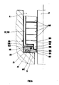
- FIGS. 2a and 2c correspond to the example of sealing system described below, usable with valves for pipes containing steam superheated at about 10 MPa -200 ° C.
- the sealing device (1) is associated with a valve stem (2) of diameter 30.0 mm and with a valve body (3) defining with the stem (2) an annular chamber (4) 46.0 mm in diameter, 84 mm deep, and ending in a flat bottom (5) pierced with an orifice (6) for passage of the rod (2), orifice (6) with the same axis of symmetry of revolution as the cylindrical lateral surface (7) of the chamber (4) and of diameter 31.0 mm.
- the extractable sleeve (8) is made of AISI 316L stainless steel, with a total height of 64 mm and an external diameter of 45.9 mm, with a smooth and cylindrical external lateral surface (9) circular over this entire height. It has an annular bottom (10) of total thickness 6 mm, the inner edge (11) or edge of its orifice (12) for passage of the rod, has a diameter of 31 mm. Above this bottom (10), the inner surface (13) of the side wall (14) of the sleeve (8) is circular cylindrical and of diameter 40.0 mm on a height of 51 mm, the portion of upper end (15) of the sleeve comprising (FIG. 2b), above a chamfer (16) intended to facilitate the introduction of the annular sealing means (17), an internally threaded part (18) M 42, 5 mm x 1.5 mm pitch over a height of 6 mm.
- the annular sealing means (17) inserted in the sleeve (8) include 6 rings (19) FARGRAF (registered trademark of the company CEFILAC) in expanded graphite, molded and compressed each with an internal diameter of 30 mm X external diameter 40 mm x thickness 7.5 mm and specific mass 1.6 g / cm3, the stacking of these rings (19) being framed by 2 anti-extrusion rings (20) placed respectively below and above this stacking, each having an internal diameter of 30.2 mm x outside diameter 39.95 mm x thickness 2 mm, in steel with anti-friction surface treatment allowing occasional friction with the valve stem (2) without hurting this stem (2).
- FARGRAF registered trademark of the company CEFILAC
- the underside (21) of the bottom (10) of the sleeve has a circular groove (22) of the same axis of symmetry of revolution with dimensions of internal diameter 34 mm x external diameter 42 mm x depth 3.2 mm, of cross section U-shaped, that is to say with a flat bottom (23) and a lateral surface perpendicular to this bottom.
- the external tightness of the sleeve (2) ensured by a lower seal (24)
- ORIGRAF registered trademark of CEFILAC
- This seal (24) is embedded in the groove (22) and the sealing in service is obtained by axial tightening until contact with the face (21) of the bottom (10) of the sleeve (8) with the flat bottom ( 5) of the annular chamber (4).
- the axial clamping means compressing all the sealing rings (19,24) comprise a conventional gland (25) of bearing portion (26) with an internal diameter of 31 mm and an external diameter of 45.8 mm, coming from the prior device and not entering the sleeve (8), and an intermediate compression ring (27) of inside and outside diameters 31 and 39.8 mm and height 20 mm.
- Figures 2a and 2c respectively represent, apart from this particular example, extraction means carried by the top of other sockets according to the invention, namely: holes radial (28) ( Figure 2a), and holes (29) threaded through the thickness ( Figure 2c).
- the external extraction means (30) used to disassemble the device d sealing (1) comprises only two parts (31) and (32): - a hollow bronze tube (31) material not injuring the seals, with an internal diameter of 32 mm, externally threaded M 42.5 mm x pitch 1.5 mm over its entire length of 220 mm except the chamfers of extremities; an extraction piece (32) made of stainless steel, with an outside diameter of 75 mm and a total height of 76 mm, comprising, from its lower support face (33), an axial internal housing (34) with a diameter of 46 mm and of height 66 mm, and at its upper part a laterally machined portion in the form of a hexagon (35) of 60 mm on flats x height 10 mm with a threaded opening M 42.5 mm x pitch 1.5 mm passing through the upper wall (36) of the housing (34), here coincid
- the extraction of the sealing device (1) is carried out as follows: the threaded tube (31) is screwed into the sleeve (8) until it is locked, then the extraction part (32) is lowered by screwing this part on the threaded tube (31) until contact with the valve body (3). Then, having immobilized the threaded tube (31) in rotation either manually or using a key, the tube (31) carrying at its upper end a hexagon machined in its mass of 36 mm on plates x height 8 mm, we continue to screw the extraction part (32) on the tube (31) using its hexagon (35) and a wrench. The threaded tube (31) is thus mounted on which the extractable sleeve (8) is hung, and screwing is continued until the top of this sleeve (8) stops on the top (37) of the interior housing (34). .
- FIG. 4 schematically represents a sealing device, the installation and extraction of which can be carried out without the drive end of the valve stem (2) being released.
- the sleeve (80) is composed of 2 contiguous semi-cylindrical parts (81), each comprising a cylindrical side wall (140) and an annular bottom portion (100) having a clearance of several mm relative to the valve stem (2) , and a complementary annular bottom (101), extractable by means of threaded rods screwed into 2 threaded holes (102) carried by its upper face (103).
- This extractable bottom (101) has under its lower face (21) a lower seal (24) made of molded and compressed expanded graphite, sealing the bottom (5) of the annular chamber (4).
- the bottom (101) has a central annular zone (104) of lesser thickness, the corresponding hollow surface (105) defining with the valve stem (2) an annular housing (106).
- the central orifice (107) of this bottom has a small clearance relative to the valve stem (2), the surface (105) then having an anti-extrusion role.
- the following practical example can be given relating to a valve stem (2) of diameter 30.0 mm and to an annular chamber of diameter 46.0 mm as in the previous examples, without going back over the means of extraction which are not shown: - the extractable bottom (101), in steel with a treatment of anti-friction surface of the surfaces which can rub on the valve stem (2), has a central opening (107) of 30.2 mm in diameter, a total thickness of 10 mm and a central annular zone of thickness 6 mm and outer diameter 35 mm. Its outside diameter is 45.95 mm.
- Its lower face (21) has the same groove or groove (22) as previously, with the same lower seal (24) embedded in this groove (22); - the semi-cylindrical parts (81) have a thickness of 3 mm, both for their side walls (140) and for their annular bottom portions (100), and the internal diameter of these contiguous annular portions (100) is 35 mm ; the annular sealing means, each segmented into two contiguous parts, include: .
- the sealing system of the invention can be used with all types of taps or valves allowing its installation, usually within the limits already indicated at the beginning of this description.
Landscapes
- Engineering & Computer Science (AREA)
- General Engineering & Computer Science (AREA)
- Mechanical Engineering (AREA)
- Details Of Valves (AREA)
- Lift Valve (AREA)
- Containers And Packaging Bodies Having A Special Means To Remove Contents (AREA)
- Closures For Containers (AREA)
- Multiple-Way Valves (AREA)
- Nozzles (AREA)
- Prostheses (AREA)
- Load-Engaging Elements For Cranes (AREA)
- Other Liquid Machine Or Engine Such As Wave Power Use (AREA)
- Purses, Travelling Bags, Baskets, Or Suitcases (AREA)
Priority Applications (1)
| Application Number | Priority Date | Filing Date | Title |
|---|---|---|---|
| AT87420248T ATE49644T1 (de) | 1986-09-26 | 1987-09-23 | Dichtungsvorrichtung zwischen spindel und ventilgehaeuse und damit uebereinstimmende, herausziehbare huelse. |
Applications Claiming Priority (2)
| Application Number | Priority Date | Filing Date | Title |
|---|---|---|---|
| FR8613643A FR2604505B1 (fr) | 1986-09-26 | 1986-09-26 | Systeme d'etancheite entre tige et corps de vanne et douille extractible correspondante |
| FR8613643 | 1986-09-26 |
Publications (2)
| Publication Number | Publication Date |
|---|---|
| EP0263042A1 true EP0263042A1 (de) | 1988-04-06 |
| EP0263042B1 EP0263042B1 (de) | 1990-01-17 |
Family
ID=9339418
Family Applications (1)
| Application Number | Title | Priority Date | Filing Date |
|---|---|---|---|
| EP87420248A Expired - Lifetime EP0263042B1 (de) | 1986-09-26 | 1987-09-23 | Dichtungsvorrichtung zwischen Spindel und Ventilgehäuse und damit übereinstimmende, herausziehbare Hülse |
Country Status (6)
| Country | Link |
|---|---|
| EP (1) | EP0263042B1 (de) |
| AT (1) | ATE49644T1 (de) |
| DE (1) | DE3761456D1 (de) |
| ES (1) | ES2012499B3 (de) |
| FR (1) | FR2604505B1 (de) |
| GR (1) | GR3004001T3 (de) |
Cited By (6)
| Publication number | Priority date | Publication date | Assignee | Title |
|---|---|---|---|---|
| EP0369210A1 (de) * | 1988-11-17 | 1990-05-23 | Combustion Engineering, Inc. | Dichtung mit Packungsträger |
| US5323428A (en) * | 1992-12-31 | 1994-06-21 | Combustion Engineering, Inc. | Readily disconnectable nozzle arrangement for use with nuclear reactor |
| US5513227A (en) * | 1992-12-31 | 1996-04-30 | Combustion Engineering Inc. | Readily disconnectable nozzle arrangement for use with a nuclear reactor |
| CN102644760A (zh) * | 2012-04-26 | 2012-08-22 | 西南石油大学 | 一种超高压针阀的密封结构 |
| CN108825784A (zh) * | 2018-08-08 | 2018-11-16 | 淮南中泰矿山装备制造有限公司 | 顶管掘进机主轴防水结构 |
| WO2019094163A1 (en) * | 2017-11-09 | 2019-05-16 | Fisher Controls International Llc | Methods and apparatus to install valve packing components |
Citations (9)
| Publication number | Priority date | Publication date | Assignee | Title |
|---|---|---|---|---|
| US2486939A (en) * | 1944-08-02 | 1949-11-01 | Phillips Petroleum Co | Stuffing box |
| GB934055A (en) * | 1960-05-06 | 1963-08-14 | Hendrik Albert Nieboer | Improvements relating to fluid control valves |
| US3257095A (en) * | 1962-12-12 | 1966-06-21 | Chester A Siver | Valve construction particularly packed or sealed |
| DE1267923B (de) * | 1967-03-31 | 1968-05-09 | Erich Herion | Durchgangsventil |
| DE2319607A1 (de) * | 1973-04-18 | 1974-10-31 | Wepuko Hydraulik Gmbh | Kolbenabdichtung in hochdruckzylindern, beispielsweise bei hochdruckpumpen |
| DE2460456A1 (de) * | 1974-12-20 | 1976-06-24 | Voith Gmbh J M | Vorrichtung zum abdichten der rotorwelle eines stoffloesers |
| US4299395A (en) * | 1980-04-21 | 1981-11-10 | Reed Lehman T | Geothermal well head assembly |
| DE3345116A1 (de) * | 1982-12-14 | 1984-06-14 | Osakeyhtiö Safematic Ltd., 40951 Muurame | Dichtungsbuchse fuer eine pumpe, fuer ein ventil und dergleichen |
| DE3302683C1 (de) * | 1983-01-27 | 1984-08-30 | Potthoff & Flume GmbH, 4670 Lünen | Berührungsdichtung für eine axial feststehende Welle oder Spindel |
Family Cites Families (1)
| Publication number | Priority date | Publication date | Assignee | Title |
|---|---|---|---|---|
| JPS5813260A (ja) * | 1981-07-15 | 1983-01-25 | Oishi Kikai Seisakusho:Kk | グランドパッキンの取出しを容易としたパッキン取付構造 |
-
1986
- 1986-09-26 FR FR8613643A patent/FR2604505B1/fr not_active Expired
-
1987
- 1987-09-23 AT AT87420248T patent/ATE49644T1/de not_active IP Right Cessation
- 1987-09-23 ES ES87420248T patent/ES2012499B3/es not_active Expired - Lifetime
- 1987-09-23 DE DE8787420248T patent/DE3761456D1/de not_active Expired - Fee Related
- 1987-09-23 EP EP87420248A patent/EP0263042B1/de not_active Expired - Lifetime
-
1990
- 1990-02-13 GR GR890400132T patent/GR3004001T3/el unknown
Patent Citations (9)
| Publication number | Priority date | Publication date | Assignee | Title |
|---|---|---|---|---|
| US2486939A (en) * | 1944-08-02 | 1949-11-01 | Phillips Petroleum Co | Stuffing box |
| GB934055A (en) * | 1960-05-06 | 1963-08-14 | Hendrik Albert Nieboer | Improvements relating to fluid control valves |
| US3257095A (en) * | 1962-12-12 | 1966-06-21 | Chester A Siver | Valve construction particularly packed or sealed |
| DE1267923B (de) * | 1967-03-31 | 1968-05-09 | Erich Herion | Durchgangsventil |
| DE2319607A1 (de) * | 1973-04-18 | 1974-10-31 | Wepuko Hydraulik Gmbh | Kolbenabdichtung in hochdruckzylindern, beispielsweise bei hochdruckpumpen |
| DE2460456A1 (de) * | 1974-12-20 | 1976-06-24 | Voith Gmbh J M | Vorrichtung zum abdichten der rotorwelle eines stoffloesers |
| US4299395A (en) * | 1980-04-21 | 1981-11-10 | Reed Lehman T | Geothermal well head assembly |
| DE3345116A1 (de) * | 1982-12-14 | 1984-06-14 | Osakeyhtiö Safematic Ltd., 40951 Muurame | Dichtungsbuchse fuer eine pumpe, fuer ein ventil und dergleichen |
| DE3302683C1 (de) * | 1983-01-27 | 1984-08-30 | Potthoff & Flume GmbH, 4670 Lünen | Berührungsdichtung für eine axial feststehende Welle oder Spindel |
Non-Patent Citations (1)
| Title |
|---|
| PATENT ABSTRACTS OF JAPAN, vol. 6, no. 89 (M-207)[1234]; & JP-A-58 13 260 (OOISHI KIKAI SEISAKUSHO K.K.) 25-01-1983 * |
Cited By (8)
| Publication number | Priority date | Publication date | Assignee | Title |
|---|---|---|---|---|
| EP0369210A1 (de) * | 1988-11-17 | 1990-05-23 | Combustion Engineering, Inc. | Dichtung mit Packungsträger |
| US5323428A (en) * | 1992-12-31 | 1994-06-21 | Combustion Engineering, Inc. | Readily disconnectable nozzle arrangement for use with nuclear reactor |
| US5513227A (en) * | 1992-12-31 | 1996-04-30 | Combustion Engineering Inc. | Readily disconnectable nozzle arrangement for use with a nuclear reactor |
| CN102644760A (zh) * | 2012-04-26 | 2012-08-22 | 西南石油大学 | 一种超高压针阀的密封结构 |
| CN102644760B (zh) * | 2012-04-26 | 2013-08-28 | 西南石油大学 | 一种超高压针阀的密封结构 |
| WO2019094163A1 (en) * | 2017-11-09 | 2019-05-16 | Fisher Controls International Llc | Methods and apparatus to install valve packing components |
| US10746320B2 (en) | 2017-11-09 | 2020-08-18 | Fisher Controls International Llc | Methods and apparatus to install valve packing components |
| CN108825784A (zh) * | 2018-08-08 | 2018-11-16 | 淮南中泰矿山装备制造有限公司 | 顶管掘进机主轴防水结构 |
Also Published As
| Publication number | Publication date |
|---|---|
| EP0263042B1 (de) | 1990-01-17 |
| FR2604505B1 (fr) | 1989-03-03 |
| ES2012499B3 (es) | 1990-04-01 |
| FR2604505A1 (fr) | 1988-04-01 |
| DE3761456D1 (de) | 1990-02-22 |
| ATE49644T1 (de) | 1990-02-15 |
| GR3004001T3 (de) | 1993-03-16 |
Similar Documents
| Publication | Publication Date | Title |
|---|---|---|
| EP0177397B1 (de) | Ventil mit unwechselbarem Sitz und schneller Instandsetzung | |
| FR2520829A1 (fr) | Joint metal sur metal | |
| FR2593259A1 (fr) | Joint d'etancheite, notamment pour soupape, et soupape munie dudit joint | |
| EP2688741B1 (de) | Presse mit verbesserter stütze | |
| FR2524057A1 (fr) | Outil de forage a fraise rotative, et procede d'assemblage et de montage d'un element de coupe pour un tel outil | |
| FR2852076A1 (fr) | Procede de realisation d'un joint filete tubulaire etanche par expansion radiale | |
| EP0263042B1 (de) | Dichtungsvorrichtung zwischen Spindel und Ventilgehäuse und damit übereinstimmende, herausziehbare Hülse | |
| LU85606A1 (fr) | Garniture d'etancheite pour joints de tuyaux en fonte | |
| EP1618324B1 (de) | Fluidstromregelventilvorrichtung | |
| EP0526373B1 (de) | Verriegelbare Rohrverbindung mit Abdichtanordnung aus einem Verbundwerkstoff | |
| CA1308758C (fr) | Dispositif de prise de branchement sur une canalisation | |
| EP0428433B1 (de) | Vorrichtung zum Fixieren der Steuerstabsführungsplatte im Kernreaktordruckgefäss | |
| FR2866094A1 (fr) | Raccord mecanique destine a assurer la solidarisation d'un tuyau en matiere plastique a un appareil de robinetterie | |
| FR2568656A1 (fr) | Dispositif d'etancheite | |
| FR2694063A1 (fr) | Joint verrouillé à emboîtement entre éléments tubulaires. | |
| FR2690726A1 (fr) | Double siège arrière sélectif pour tiges de vanne. | |
| EP1445046A1 (de) | Vorrichtung zum Befestigen einer Leitung für die Zirkulation eines Fluids an ein feuerfestes Bauteil und feuerfestes Bauteil | |
| FR2708323A1 (fr) | Soupape sphérique et son procédé de fabrication. | |
| FR2997119A1 (fr) | Ensemble pour la fixation temporaire au sol de tout type d'equipement pour l'agencement d'espaces en vue d'evenements specifiques | |
| EP0034101B1 (de) | Abnehmbare Verbindung, insbesondere zum Verbinden zweier Röhren oder Leitungen | |
| EP3597976A1 (de) | Leicht handhabbarer fluidanschluss | |
| EP4007863B1 (de) | Tankverschlussvorrichtung und tank | |
| FR2507733A1 (fr) | Vanne a passage direct | |
| BE898637A (fr) | Vanne-porte | |
| FR2678997A1 (fr) | Joint d'etancheite a ame metallique et garnitures en graphite expanse. |
Legal Events
| Date | Code | Title | Description |
|---|---|---|---|
| PUAI | Public reference made under article 153(3) epc to a published international application that has entered the european phase |
Free format text: ORIGINAL CODE: 0009012 |
|
| AK | Designated contracting states |
Kind code of ref document: A1 Designated state(s): AT BE CH DE ES GB GR IT LI LU NL SE |
|
| 17P | Request for examination filed |
Effective date: 19880520 |
|
| 17Q | First examination report despatched |
Effective date: 19890316 |
|
| RAP1 | Party data changed (applicant data changed or rights of an application transferred) |
Owner name: LE CARBONE-LORRAINE S.A. |
|
| RAP1 | Party data changed (applicant data changed or rights of an application transferred) |
Owner name: LE CARBONE LORRAINE |
|
| GRAA | (expected) grant |
Free format text: ORIGINAL CODE: 0009210 |
|
| AK | Designated contracting states |
Kind code of ref document: B1 Designated state(s): AT BE CH DE ES GB GR IT LI LU NL SE |
|
| REF | Corresponds to: |
Ref document number: 49644 Country of ref document: AT Date of ref document: 19900215 Kind code of ref document: T |
|
| GBT | Gb: translation of ep patent filed (gb section 77(6)(a)/1977) | ||
| REF | Corresponds to: |
Ref document number: 3761456 Country of ref document: DE Date of ref document: 19900222 |
|
| ITF | It: translation for a ep patent filed | ||
| PLBE | No opposition filed within time limit |
Free format text: ORIGINAL CODE: 0009261 |
|
| STAA | Information on the status of an ep patent application or granted ep patent |
Free format text: STATUS: NO OPPOSITION FILED WITHIN TIME LIMIT |
|
| 26N | No opposition filed | ||
| PGFP | Annual fee paid to national office [announced via postgrant information from national office to epo] |
Ref country code: GR Payment date: 19910729 Year of fee payment: 5 |
|
| PGFP | Annual fee paid to national office [announced via postgrant information from national office to epo] |
Ref country code: GB Payment date: 19910805 Year of fee payment: 5 |
|
| PGFP | Annual fee paid to national office [announced via postgrant information from national office to epo] |
Ref country code: AT Payment date: 19910814 Year of fee payment: 5 |
|
| PGFP | Annual fee paid to national office [announced via postgrant information from national office to epo] |
Ref country code: SE Payment date: 19910816 Year of fee payment: 5 Ref country code: DE Payment date: 19910816 Year of fee payment: 5 |
|
| PGFP | Annual fee paid to national office [announced via postgrant information from national office to epo] |
Ref country code: CH Payment date: 19910819 Year of fee payment: 5 |
|
| PGFP | Annual fee paid to national office [announced via postgrant information from national office to epo] |
Ref country code: LU Payment date: 19910828 Year of fee payment: 5 |
|
| PGFP | Annual fee paid to national office [announced via postgrant information from national office to epo] |
Ref country code: ES Payment date: 19910905 Year of fee payment: 5 |
|
| ITTA | It: last paid annual fee | ||
| PGFP | Annual fee paid to national office [announced via postgrant information from national office to epo] |
Ref country code: NL Payment date: 19910930 Year of fee payment: 5 |
|
| PGFP | Annual fee paid to national office [announced via postgrant information from national office to epo] |
Ref country code: BE Payment date: 19911001 Year of fee payment: 5 |
|
| EPTA | Lu: last paid annual fee | ||
| PG25 | Lapsed in a contracting state [announced via postgrant information from national office to epo] |
Ref country code: LU Free format text: LAPSE BECAUSE OF NON-PAYMENT OF DUE FEES Effective date: 19920923 Ref country code: GB Effective date: 19920923 Ref country code: AT Effective date: 19920923 |
|
| PG25 | Lapsed in a contracting state [announced via postgrant information from national office to epo] |
Ref country code: SE Effective date: 19920924 Ref country code: ES Free format text: LAPSE BECAUSE OF EXPIRATION OF PROTECTION Effective date: 19920924 |
|
| PG25 | Lapsed in a contracting state [announced via postgrant information from national office to epo] |
Ref country code: LI Effective date: 19920930 Ref country code: CH Effective date: 19920930 Ref country code: BE Effective date: 19920930 |
|
| REG | Reference to a national code |
Ref country code: GR Ref legal event code: FG4A Free format text: 3004001 |
|
| BERE | Be: lapsed |
Owner name: LE CARBONE LORRAINE Effective date: 19920930 |
|
| PG25 | Lapsed in a contracting state [announced via postgrant information from national office to epo] |
Ref country code: GR Free format text: THE PATENT HAS BEEN ANNULLED BY A DECISION OF A NATIONAL AUTHORITY Effective date: 19930331 |
|
| PG25 | Lapsed in a contracting state [announced via postgrant information from national office to epo] |
Ref country code: NL Effective date: 19930401 |
|
| NLV4 | Nl: lapsed or anulled due to non-payment of the annual fee | ||
| GBPC | Gb: european patent ceased through non-payment of renewal fee |
Effective date: 19920923 |
|
| REG | Reference to a national code |
Ref country code: CH Ref legal event code: PL |
|
| PG25 | Lapsed in a contracting state [announced via postgrant information from national office to epo] |
Ref country code: DE Effective date: 19930602 |
|
| REG | Reference to a national code |
Ref country code: GR Ref legal event code: MM2A Free format text: 3004001 |
|
| EUG | Se: european patent has lapsed |
Ref document number: 87420248.4 Effective date: 19930406 |
|
| REG | Reference to a national code |
Ref country code: ES Ref legal event code: FD2A Effective date: 19990601 |
|
| PG25 | Lapsed in a contracting state [announced via postgrant information from national office to epo] |
Ref country code: IT Free format text: LAPSE BECAUSE OF NON-PAYMENT OF DUE FEES;WARNING: LAPSES OF ITALIAN PATENTS WITH EFFECTIVE DATE BEFORE 2007 MAY HAVE OCCURRED AT ANY TIME BEFORE 2007. THE CORRECT EFFECTIVE DATE MAY BE DIFFERENT FROM THE ONE RECORDED. Effective date: 20050923 |