EP1618324B1 - Fluid flow control valve device - Google Patents
Fluid flow control valve device Download PDFInfo
- Publication number
- EP1618324B1 EP1618324B1 EP04742830A EP04742830A EP1618324B1 EP 1618324 B1 EP1618324 B1 EP 1618324B1 EP 04742830 A EP04742830 A EP 04742830A EP 04742830 A EP04742830 A EP 04742830A EP 1618324 B1 EP1618324 B1 EP 1618324B1
- Authority
- EP
- European Patent Office
- Prior art keywords
- seat
- valve
- seal
- housing
- counter
- Prior art date
- Legal status (The legal status is an assumption and is not a legal conclusion. Google has not performed a legal analysis and makes no representation as to the accuracy of the status listed.)
- Expired - Lifetime
Links
- 239000012530 fluid Substances 0.000 title claims description 24
- 238000007789 sealing Methods 0.000 claims abstract description 28
- 239000000463 material Substances 0.000 claims description 16
- 230000006835 compression Effects 0.000 claims description 14
- 238000007906 compression Methods 0.000 claims description 14
- OKTJSMMVPCPJKN-UHFFFAOYSA-N Carbon Chemical compound [C] OKTJSMMVPCPJKN-UHFFFAOYSA-N 0.000 claims description 11
- 229910002804 graphite Inorganic materials 0.000 claims description 11
- 239000010439 graphite Substances 0.000 claims description 11
- 229910001220 stainless steel Inorganic materials 0.000 claims description 8
- 239000010935 stainless steel Substances 0.000 claims description 8
- 238000004891 communication Methods 0.000 claims description 7
- 230000002093 peripheral effect Effects 0.000 claims description 7
- 230000000284 resting effect Effects 0.000 claims description 7
- 210000004907 gland Anatomy 0.000 claims description 3
- 238000012856 packing Methods 0.000 claims description 2
- 230000000977 initiatory effect Effects 0.000 claims 1
- 210000001699 lower leg Anatomy 0.000 claims 1
- 101000793686 Homo sapiens Azurocidin Proteins 0.000 description 13
- 208000031968 Cadaver Diseases 0.000 description 8
- 238000012423 maintenance Methods 0.000 description 6
- 230000005855 radiation Effects 0.000 description 5
- XLYOFNOQVPJJNP-UHFFFAOYSA-N water Substances O XLYOFNOQVPJJNP-UHFFFAOYSA-N 0.000 description 4
- 230000009471 action Effects 0.000 description 3
- 239000000470 constituent Substances 0.000 description 3
- 235000021183 entrée Nutrition 0.000 description 3
- 238000000605 extraction Methods 0.000 description 3
- 238000003754 machining Methods 0.000 description 3
- 239000002184 metal Substances 0.000 description 3
- 229910052751 metal Inorganic materials 0.000 description 3
- 230000002285 radioactive effect Effects 0.000 description 3
- 235000008612 Gnetum gnemon Nutrition 0.000 description 2
- 240000000018 Gnetum gnemon Species 0.000 description 2
- 229910017052 cobalt Inorganic materials 0.000 description 2
- 239000010941 cobalt Substances 0.000 description 2
- GUTLYIVDDKVIGB-UHFFFAOYSA-N cobalt atom Chemical compound [Co] GUTLYIVDDKVIGB-UHFFFAOYSA-N 0.000 description 2
- 230000001276 controlling effect Effects 0.000 description 2
- 238000006073 displacement reaction Methods 0.000 description 2
- 230000000694 effects Effects 0.000 description 2
- 230000004992 fission Effects 0.000 description 2
- 239000007788 liquid Substances 0.000 description 2
- 125000006850 spacer group Chemical group 0.000 description 2
- 241001644893 Entandrophragma utile Species 0.000 description 1
- 230000008859 change Effects 0.000 description 1
- 238000006243 chemical reaction Methods 0.000 description 1
- 238000001816 cooling Methods 0.000 description 1
- 238000005242 forging Methods 0.000 description 1
- 239000000446 fuel Substances 0.000 description 1
- 239000004519 grease Substances 0.000 description 1
- 238000009434 installation Methods 0.000 description 1
- 230000005226 mechanical processes and functions Effects 0.000 description 1
- 238000000465 moulding Methods 0.000 description 1
- 210000002445 nipple Anatomy 0.000 description 1
- 239000011824 nuclear material Substances 0.000 description 1
- 239000002245 particle Substances 0.000 description 1
- 238000005192 partition Methods 0.000 description 1
- 238000003825 pressing Methods 0.000 description 1
- 230000001105 regulatory effect Effects 0.000 description 1
- 239000007787 solid Substances 0.000 description 1
Images

Classifications
-
- F—MECHANICAL ENGINEERING; LIGHTING; HEATING; WEAPONS; BLASTING
- F16—ENGINEERING ELEMENTS AND UNITS; GENERAL MEASURES FOR PRODUCING AND MAINTAINING EFFECTIVE FUNCTIONING OF MACHINES OR INSTALLATIONS; THERMAL INSULATION IN GENERAL
- F16K—VALVES; TAPS; COCKS; ACTUATING-FLOATS; DEVICES FOR VENTING OR AERATING
- F16K27/00—Construction of housing; Use of materials therefor
- F16K27/02—Construction of housing; Use of materials therefor of lift valves
-
- F—MECHANICAL ENGINEERING; LIGHTING; HEATING; WEAPONS; BLASTING
- F16—ENGINEERING ELEMENTS AND UNITS; GENERAL MEASURES FOR PRODUCING AND MAINTAINING EFFECTIVE FUNCTIONING OF MACHINES OR INSTALLATIONS; THERMAL INSULATION IN GENERAL
- F16K—VALVES; TAPS; COCKS; ACTUATING-FLOATS; DEVICES FOR VENTING OR AERATING
- F16K1/00—Lift valves or globe valves, i.e. cut-off apparatus with closure members having at least a component of their opening and closing motion perpendicular to the closing faces
- F16K1/32—Details
- F16K1/34—Cutting-off parts, e.g. valve members, seats
- F16K1/42—Valve seats
Definitions
- the object of the present invention is to improve the fluid flow control valve devices in pipelines, such as valves or flapper valves, preferably with a removable and quick-maintenance seat.
- the present invention relates to a valve or a valve valve used in particular in nuclear facilities and whose disassembly, in particular that of the seat is preferably easy.
- the energy produced by the fission reaction of the nuclear material constituting the core of the reactor is transmitted to a primary heat exchanger by a so-called primary water flow between the reactor vessel and the reactor.
- primary heat exchanger Although the combustible material is enclosed in a sealed sheath of the fuel element, there is always a risk of cracks in this sheath that can cause a passage of fission products in the primary water. It is therefore necessary for all the elements forming the primary circuit to provide excellent containment.
- the primary water contain no particles of a material capable of producing a product. radioactive. It is therefore important that none of the components of the primary circuit is made using a material capable of giving a radioactive product under the effect of radiation. This is particularly the case of cobalt.
- This valve valve and seat removable and quick maintenance comprises a control rod in translation along the axis of the valve, operating means for controlling the translational movement of said rod, a valve secured to an end of said rod, a body pierced with inlet and outlet passages of the liquid opening into a cavity extended by a cylindrical orifice disposed along the axis of said valve for the passage of said rod, a cage housed in said cavity and in which can move said valve under the action of said rod, lining elements surrounding a portion of said rod and a seat to cooperate with said valve in the closed position.
- Said faucet is characterized in that said seat is formed by a separate part of said body. A seal is interposed between the body and the removable seat.
- the removable seat is constituted by a cylindrical sleeve and an external collar on which the cage rests, itself surmounted by the sealing blocks and by the gland.
- the valve can move inside the cage.
- the seal is disposed under the underside of the seat flange.
- An annular ring cooperates with the cylindrical sleeve for the confinement of the seal, also bearing on the inner wall of the hollow body of the valve.
- the cylindrical sleeve has a height greater than that of the seal and supports most of the confinement of this seal (pressure of 700 bar). It has been found that, in use, a structure of this type can cause deformation of the seat and consequently a sealing problem at the contact of the valve with the upper part of the seat, namely the flange. , e .g. warping of the frustoconical contact part of the seat.
- one of the essential objectives of the present invention is to improve the devices with flow control valves (eg valves, valves) in pipes, the devices considered being those of the prior art, in particular according to EP-B-0 177 397 and the improvements sought to limit or even eliminate the wear of their constituent mechanical parts subjected to very high mechanical stresses, to thereby ensure sealing over very long periods of time. use.
- flow control valves eg valves, valves
- Another essential objective of the present invention is to provide the aforementioned improvements for both fluid flow control devices with easy disassembly and maintenance as for devices not having this characteristic.
- Another essential objective of the present invention is to improve the devices with flow control valves without burdening the cost of the device.
- Another essential objective of the present invention is to improve the sealing of devices with flow control valves (of faucet type) - preferably with easy disassembly and maintenance -, whether it is also about the sealing on both sides of the valve / seat system in the closed position, as sealing at the control rod.
- Another essential objective of the present invention is to improve the devices with flow control valves, by implementing simple and robust parts and a structure.
- the seat In addition to this axial compression transmitted to it by the cage, the seat also supports the compressive stress of the valve, it is particularly clever in accordance with the invention to release the seat of at least a part of its role of sealing in the transferring to the counter seat, the latter contributing in this perspective to most of the containment of the seal.
- valve device according to the invention provides the valve device according to the invention a high robustness and increased durability.
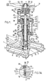
- FIGS 1, 1A & 1B show an embodiment of the device according to the invention corresponding to a flapper valve, with removable seat and quick maintenance.
- the valve comprises a metal hollow body 1 obtained e.g. by molding and machining and having an inlet passage 2 and a fluid outlet passage 3, both communicating with a housing 4 disposed along the axis XX 'of the valve.
- the device according to the invention is superposed and compressed in the housing 4, from top to bottom, the annular seal 15, the cage 8, the seat 10, the seal 13 and the counter-seal. seat 11, all these elements (preferably removable) being included in the assembly designated by the reference 5 in this presentation.
- FIG. 1A shows the detail of the structure of this confinement chamber of the lower annular seal 13.
- the total area of the two lateral annular bearing surfaces 20 1 and lower 20 2 defined by a portion of the counter seat 11, is at least 1.1, preferably at least 1.5, and more preferably at least 2 times greater than that of the upper annular bearing surface 19 defined by a part of the seat 10.
- the counter seat 11 is a cylindrical sleeve whose lower end forms an outer collar 21, resting on the shoulder 12 of the body 1 inside the housing 4 containing the elements 7, 10, 13, 11, preferably removable.
- the seat 10 is a ring bearing on the upper end of the cylindrical sleeve constituting the counter seat 11.
- This ring 10 preferably has a peripheral lip 22 extending downwards from the underside of said ring. .
- Said lip is designed to be inserted into the annular containment chamber delimited by the cylindrical sleeve forming the counter-seat 11 with its outer lateral annular bearing surfaces 20 1 and lower 2 and the inner face 18 of the housing 4 forming the lateral annular bearing surface external, the upper annular bearing surface 19 thus being constituted by the lower end surface of the aforesaid peripheral lip 22.
- cylindrical sleeve of the counter seat 11 has a height such that it acts as a crush limiter of the seal 13 by the lower peripheral lip 22 of the seat 10.
- the annular lower seal 13 has a right cross section of generally rectangular or circular shape.
- the annular seal 13 is of a nature and / or elastic form, graphite, preferably expanded graphite, being especially suitable as constituent material of said annular seal.
- the seat 10 is a ring having an internal upper corner 23 bevelled.
- This chamfered surface constitutes an annular bearing surface intended to cooperate with a corresponding annular contact surface, provided on the outer surface of a frustoconical portion of the spherical cap forming the lower end of the valve 6.
- the material or materials constituting the parts comprising these annular bearing surfaces being preferably selected from harder materials than stainless steel.
- the ring forming the seat 10 comprises, as appears more clearly in FIG. 1A, a chamfered inner top corner 23 is advantageously lapped and / or constituted by a material different from that of the In practice, this chamfered corner 23 is preferably harder than stainless steel and makes it possible to perfect the tightness of the shutter valve / seat.
- the chamfered face of this upper inner corner 23 constitutes the annular bearing surface for a corresponding annular contact surface, provided on a frustoconical portion of the lower end of the valve 6. This frustoconical portion constitutes the base of the cap spherical forming the lower end of said valve 6.
- annular contact surface of the valve 6 is part of a terminal contact ring 24 of said valve 6 ( Figures 1A and 1B).
- This end contact ring 24 is made of a ground material or a material different from that constituting the rest of the valve 6 and of the same nature or of a similar nature to that of the upper inner corner 23 of the seat 10. In this case, this material is also preferably harder than stainless steel
- the upper face of the seat ring 10 is disposed in a plane diametrical with respect to XX 'of said seat ring 10. This upper face 25 forms an annular bearing surface for the lower end 26 of the cage. guide 8 of the valve 6 ( Figure 1A).
- the tubular guiding guide 8 is pierced with orifices 9 in its lower part. These orifices 9 open into the housing 4 and are opposite the outlet passage 3 of axis ZZ '.
- the lower section and the median section of the cage 8 both have identical and constant internal and external diameters, while the upper section of this cage 8 form a flare 28 of outer diameter slightly greater than the outer diameter of its median and lower sections and internal diameter identical to the constant internal diameter of the cage 8.
- the flare 28 of the cage 8 has a shoulder 29 on which rests the upper annular seal 15 .
- the valve 6 is a substantially solid cylindrical piece for which it has already been stated supra that its lower end is shaped spherical cap. This cylindrical piece is secured to the control rod 7 via a mortise 30 for receiving a pin 31 constituting the lower end of the control rod 7.
- This pin comprises a terminal collar 32 ( Figure 1B).
- a chamfered flange 33 provided on the rod 7 constitutes the base of the tenon 31 and is in annular support on the upper face of the valve 6.
- the valve 6 has at the upper end of its outer face an annular band 34 of sliding and contact with the inner face of the tubular cage 8. The role of this band 34 is to ensure sealing at the valve, like the contact ring 24 of the seat 6 with the counter- seat 11.
- this sealing sheath 16 comprises a bellows preferably stainless steel and / or gaskets, preferably graphite, and more preferably still expanded graphite.
- this sheath is a stainless steel bellows
- the upper end of this sheath gusset 16 is integral with a collar 35 itself attached to the edges of the end 36.
- upper open end of a tubular cap 37 This upper open end 36 is traversed by the rod 7.
- the tubular cap 37 is essentially disposed outside the body 1 and caps the cage 8.
- the annular upper seal 15 is interposed between the tubular cap 37 and the cage 8.
- this sheath / bellows 16 sealing associated with the collar 35, makes it possible to partition the communication existing between the inside of the cage 8 and the cap 37 in connection with the housing 4, on the one hand, and the outside of the body 1, on the other hand.
- the follower 40 rests on the annular peripheral edge 48 of the cap 37 and covers said cap being in contact with the surface of revolution of the latter through its inner face.
- the annular seal 41 interposed between the follower 40 and the cap 37 is disposed on an annular shoulder 49 of the cap 37.
- a dynamic clearance 50 is provided between the upper end of the cap 37 and the lower part of the follower 40 covering the latter.
- the upper part of the follower 40 not covering the cap 37 is a tubular part of smaller diameter than the lower tubular part.
- a circular passage for the rod 7 is provided in the follower 40 at the region separating the tubular lower part capping the cap 37 and the tubular upper part of said follower 40.
- the inner diameter of the latter is slightly greater than the diameter of the rod.
- the ring 44 of the highest crush has an upper portion in the form of a cylindrical upper sleeve 44 1 of smaller diameter than that of its lower part, said sleeve 44 1 extending above the upper end of the follower 40.
- Three spring washers 45 are threaded on the upper sleeve 44 1 . Due to the difference in thickness between the lower part of the ring 44 and the upper sleeve 44 1 of this, there is a shoulder on which rests the three spring washers 45. This shoulder being located slightly above the upper surface of the follower 40, a clearance 51 is thus formed between the washers and said upper face ( Figure 1B ).
- the upper jaw 39 rests on the follower 40 via an annular bearing surface 52 defined by the shoulder resulting from the difference in diameter between the lower part and the upper part of the follower 40.
- the jaw 39 also takes bearing on the elastic washers 45, through its annular zone bordering and delimiting the passage for the control rod 7 and the upper sleeve 44 1 of the ring 44.
- the traction means 46, 47 are constituted by at least two tie rods 47.
- the lower end of each tie bar 47 is screwed into the upper part of the body 1 forming the jaw 38, while the upper end portion of each tie rod 47 crosses the outer ring of the jaw 39.
- Said upper end portion of each tie rod 47 is threaded so as to be associated with a nut 46 for clamping the jaws 38 and 39, and, consequently, the axial compression along XX of the stacking or superposition of the following elements: follower 40, seal 41, cap 48, seal 15, cage 8, seat 10, seal 13, counter seat 11, with seal containment 13.
- the compression of this seal is determined to obtain a pressure greater than that of the fluid vis-à-vis which it is desired to seal the device.
- control rod 7 Maneuvering of the control rod 7 is carried out using an assembly 14 comprising a flywheel 53, integral in rotation and in translation with a bush 54.
- the fastening is carried out by a nut 55 screwed onto the upper end Thread 56 of the sleeve 54.
- This upper end 56 has a tapped axial orifice 57 in which the upper end 58 of the control rod 7 is screwed.
- the rotational connection of the sleeve 54 with the flywheel 53 is provided by a key 59 engaged in a radial groove of the sleeve 54 and a groove of the hub 60 of the flywheel 53.
- the immobilization in translation of the sleeve 54 is provided by a together constituted by an upper flange 61 and clamping means 62 comprising at least one play pull (s) 63 / nut (s) 64.
- the lower end of each tie rod 63 is screwed into the jaw 39, while their end upper is threaded and passes through a bore provided in the upper flange 61.
- a nut 64 screwed onto the threaded head of the tie rod 63 allows clamping of the flange 61 with respect to the jaw 39.
- the portion of the control rod 7 proximal to its threaded upper end 58 is equipped with a bar 65 secured to the control rod 7 and movable in translation therewith.
- a first function of this bar is a function of anti-rotation of the control rod.
- the second function is to indicate by its position with respect to marks placed on the tie rod 62, namely "O" for open tap and "F / C" for closed or "closed” tap. This visualizes the opening and closing of the valve.
- This bar 65 opening / closing indication is substantially orthogonal to the axis XX '.
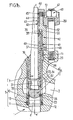
- FIGS. 2 and 3 show a second embodiment of the device according to the invention, consisting of a valve whose compression means 117 comprise at least one cap 137, preferably removable, forming a cover integrally fixed to the open upper end of the body 101, corresponding to the housing 104 containing the assembly 105, preferably removable: cage 108 / seat 110 / against seat 111, said cap 137 pressing on the cage 108 thus compressing axially along XX 'the seal 113 interposed between the seat 110 and counter-seat 111.
- a valve whose compression means 117 comprise at least one cap 137, preferably removable, forming a cover integrally fixed to the open upper end of the body 101, corresponding to the housing 104 containing the assembly 105, preferably removable: cage 108 / seat 110 / against seat 111, said cap 137 pressing on the cage 108 thus compressing axially along XX 'the seal 113 interposed between the seat 110 and counter-seat 111.
- valve 106 there are provided between the valve 106 and the cap 137 resilient return means of the valve 106 in the closed position of the valve, resting on the seat 110.
- this assembly 105 is subjected to an axial compression along the axis XX 'through the cap 137 secured integrally to the upper part of the body 101 bordering the upper open end of the housing 104.
- the fixing of the cap 137 is made using several screw systems 147 / nuts 146, in this case 6 as shown in FIG. 3.
- the cap 137 is supported on the cage 108 via an annular lip 137 1 projecting downwards.
- An annular seal 115 of rectangular cross section is interposed between this annular lip 137 1 and a shoulder of the cage 108.
- the valve 106 is equipped with a contact ring 124 with the seat 110 as well as a sliding / contact strip 134 disposed at the upper end of the valve 106. These elements 124 and 134 contribute to improving the tightness of the device. .
- the characteristic of the confinement of the gasket 113 between the seat 110 and the counter seat 111 which characteristic constitutes one of the essential characteristics of the invention, is quite analogous to this same characteristic described in relation to FIGS. 1, 1A. & 1C for the first embodiment of a device according to the invention constituted by a flapper valve.
- this valve is a non-return valve intended to prevent the backflow of fluid from the outlet passage to the housing 104 and to the inlet passage 102.
- the pressure exerted by the circulating fluid causes the valve 106 to rise and abut against the inner face of the cap 137.
- the valve is thus open and allows the fluid to flow through the housing 104. and orifices 109 of the cage 108 in the direction of the outlet passage 103.
- the valve 106 is arranged according to a rest position lowered in support on the seat 110. The return to the rest position of the valve 106 is all the more favored when one provides a resilient means (spring) that is available between the valve 106 and the inner face of the hat 137.
Abstract
Description
La présente invention a pour objet des perfectionnements aux dispositifs à clapet de régulation de débit de fluide dans des canalisations, tels que des robinets ou des valves à clapet, de préférence à siège démontable et à maintenance rapide.The object of the present invention is to improve the fluid flow control valve devices in pipelines, such as valves or flapper valves, preferably with a removable and quick-maintenance seat.
De façon plus précise la présente invention concerne un robinet ou une valve à clapet utilisable notamment dans des installations nucléaires et dont le démontage, en particulier celui du siège est de préférence aisé.More specifically, the present invention relates to a valve or a valve valve used in particular in nuclear facilities and whose disassembly, in particular that of the seat is preferably easy.
Dans les réacteurs nucléaires du type à eau sous pression, l'énergie produite par la réaction de fission du matériau nucléaire constituant le coeur du réacteur est transmise à un échangeur thermique primaire par une circulation d'eau dite primaire entre la cuve du réacteur et l'échangeur thermique primaire. Bien que le matériau combustible soit enfermé dans une gaine étanche de l'élément combustible, il existe toujours un risque de fissures dans cette gaine qui peuvent entraîner un passage de produits de fission dans l'eau primaire. Il est donc nécessaire que l'ensemble des éléments formant le circuit primaire assure un excellent confinement.In nuclear reactors of the pressurized water type, the energy produced by the fission reaction of the nuclear material constituting the core of the reactor is transmitted to a primary heat exchanger by a so-called primary water flow between the reactor vessel and the reactor. primary heat exchanger. Although the combustible material is enclosed in a sealed sheath of the fuel element, there is always a risk of cracks in this sheath that can cause a passage of fission products in the primary water. It is therefore necessary for all the elements forming the primary circuit to provide excellent containment.
En outre, on sait que dans ce type d'installation nucléaire, l'ensemble du circuit primaire est enfermé dans une enceinte de confinement dans laquelle il règne un certain rayonnement. Les interventions à l'intérieur de cette enceinte de confinement sont donc être exceptionnelles et leur durée doit être aussi réduite que possible, cela suppose que l'intervention sur chacun des composants du circuit primaire soit simple. En outre, il est important de connaître à l'avance la durée approximative de l'intervention.In addition, it is known that in this type of nuclear installation, the entire primary circuit is enclosed in a containment chamber in which there is some radiation. The interventions inside this containment chamber are therefore exceptional and their duration must be as short as possible, this supposes that the intervention on each of the components of the primary circuit is simple. In addition, it is important to know in advance the approximate duration of the intervention.
Enfin, compte tenu du rayonnement qui existe à l'intérieur de la cuve primaire du réacteur, et en particulier en raison du rayonnement neutronique, il est extrêmement souhaitable que l'eau primaire ne contienne aucune particule d'un matériau susceptible de donner un produit radioactif. Il importe donc qu'aucun des composants du circuit primaire ne soit réalisé à l'aide d'un matériau susceptible de donner un produit radioactif sous l'effet du rayonnement. C'est en particulier le cas du cobalt.Finally, given the radiation that exists inside the primary reactor vessel, and in particular because of the neutron radiation, it is extremely desirable that the primary water contain no particles of a material capable of producing a product. radioactive. It is therefore important that none of the components of the primary circuit is made using a material capable of giving a radioactive product under the effect of radiation. This is particularly the case of cobalt.
Ainsi, dans la problématique liée aux circuits primaires de refroidissement de réacteurs nucléaires, parmi les spécifications attendues pour les robinets ou les valves montés sur les différentes parties de tels circuits d'un tel nucléaire, on peut en dégager trois principales. Il est avantageux que le changement du siège du robinet ou de ses éléments d'étanchéité puisse être réalisé rapidement et à l'aide d'opérations simples. Il est également souhaitable que le robinet ne constitue pas un point faible dans le maintien du confinement du circuit primaire, en d'autres termes, il importe que le robinet présente une excellente étanchéité, en particulier vis-à-vis de l'extérieur. Enfin, il est tout à fait recommandé d'éviter d'utiliser dans l'ensemble du robinet des matériaux susceptibles de produire des produits radioactifs sous l'effet du rayonnement.Thus, in the problem related to the primary cooling circuits of nuclear reactors, among the expected specifications for the valves or valves mounted on the different parts of such circuits of such nuclear, three main can be identified. It is advantageous that the change of the seat of the valve or its sealing elements can be achieved quickly and with simple operations. It is also desirable that the valve is not a weak point in maintaining the containment of the primary circuit, in other words, it is important that the valve has an excellent seal, especially vis-à-vis the outside. Finally, it is highly recommended avoid using in the faucet assembly materials that can produce radioactive products under the influence of radiation.
Ces exigences ont été satisfaites par l'invention objet du brevet Européen EP-B-0 177 397, qui concerne un robinet comportant une soupape destinée à coopérer avec un siège et des garnitures d'étanchéité. Ce robinet est caractérisé en ce que l'extraction du siège et des garnitures d'étanchéité est aisée, en ce que l'étanchéité est parfaitement assurée et en ce que l'utilisation notamment de cobalt est évitée. Ce robinet à soupape et à siège démontable et à maintenance rapide, comprend une tige de commande en translation selon l'axe du robinet, des moyens de manoeuvre pour commander le mouvement de translation de ladite tige, un clapet solidaire d'une extrémité de ladite tige, un corps percé de passages d'entrée et de sortie du liquide débouchant dans une cavité prolongée par un orifice cylindrique disposé selon l'axe dudit robinet pour le passage de ladite tige, une cage logée dans ladite cavité et dans laquelle peut se déplacer ledit clapet sous l'action de ladite tige, des éléments de garniture entourant une portion de ladite tige et un siège pour coopérer avec ledit clapet en position de fermeture. Ledit robinet se caractérise en ce que ledit siège est formé par une pièce distincte dudit corps. Un joint d'étanchéité est interposé entre le corps et le siège amovible. Ce dernier est maintenu en place par un empilage comprimé comprenant la cage, les garnitures d'étanchéité, un fouloir, des rondelles élastiques, et une bride de fouloir. Le chapeau et la bride de fouloir sont solidarisés avec le corps par des tirants. La rotation de la tige de commande dans le sens anti-horaire permet l'extraction des garnitures d'étanchéité. La tête et le siège du robinet peuvent être aisément extraits du corps du robinet sans outillage particulier, ce qui permet de ré-usiner ou de changer ces pièces en atelier et non sur le site. Conformément au cinquième mode de réalisation de l'invention (Figure 5) selon l'EP-B-0 177 397, le siège amovible est constitué par un manchon cylindrique et une collerette externe sur laquelle prend appui la cage, elle-même surmontée par les blocs d'étanchéité et par le fouloir. Le clapet peut se déplacer à l'intérieur de la cage. Le joint d'étanchéité est disposé sous la face inférieure de la collerette du siège. Une bague annulaire coopère avec le manchon cylindrique pour le confinement du joint, également en appui sur la paroi interne du corps creux du robinet. Le manchon cylindrique a une hauteur supérieure à celle du joint et supporte l'essentiel du confinement de ce joint (pression de 700 bars). Il s'est avéré, qu'à l'usage, une structure de ce type peut entraîner une déformation du siège et par suite un problème d'étanchéité au niveau du contact du clapet avec la partie haute du siège, à savoir la collerette 32, e .g. gauchissement de la partie tronconique de contact du siège.These requirements have been met by the invention which is the subject of the European patent EP-B-0 177 397, which relates to a valve comprising a valve intended to cooperate with a seat and sealing gaskets. This valve is characterized in that the extraction of the seat and the seals is easy, in that the seal is perfectly ensured and in particular the use of cobalt is avoided. This valve valve and seat removable and quick maintenance, comprises a control rod in translation along the axis of the valve, operating means for controlling the translational movement of said rod, a valve secured to an end of said rod, a body pierced with inlet and outlet passages of the liquid opening into a cavity extended by a cylindrical orifice disposed along the axis of said valve for the passage of said rod, a cage housed in said cavity and in which can move said valve under the action of said rod, lining elements surrounding a portion of said rod and a seat to cooperate with said valve in the closed position. Said faucet is characterized in that said seat is formed by a separate part of said body. A seal is interposed between the body and the removable seat. The latter is held in place by a compressed stack comprising the cage, the packings, a follower, spring washers, and a follower flange. The cap and the plunger flange are secured to the body by tie rods. The rotation of the control rod in the counter-clockwise direction allows the extraction of the seals. The valve head and seat can be easily removed from the faucet body without special tools, allowing re-machining or changing these parts in the workshop and not on site. According to the fifth embodiment of the invention (FIG. 5) according to EP-B-0 177 397, the removable seat is constituted by a cylindrical sleeve and an external collar on which the cage rests, itself surmounted by the sealing blocks and by the gland. The valve can move inside the cage. The seal is disposed under the underside of the seat flange. An annular ring cooperates with the cylindrical sleeve for the confinement of the seal, also bearing on the inner wall of the hollow body of the valve. The cylindrical sleeve has a height greater than that of the seal and supports most of the confinement of this seal (pressure of 700 bar). It has been found that, in use, a structure of this type can cause deformation of the seat and consequently a sealing problem at the contact of the valve with the upper part of the seat, namely the flange. , e .g. warping of the frustoconical contact part of the seat.
Dans ce contexte, l'un des objectifs essentiels de la présente invention est de perfectionner les dispositifs à clapets de régulation de flux (e.g. robinets, valves) dans des canalisations, les dispositifs considérés étant ceux de l'art antérieur, en particulier selon l'EP-B-0 177 397 et les perfectionnements recherchés ayant pour but de limiter voire de supprimer l'usure de leurs pièces mécaniques constitutives soumises à de très fortes sollicitations mécaniques, pour garantir ainsi l'étanchéité sur de très longues durées d'utilisation.In this context, one of the essential objectives of the present invention is to improve the devices with flow control valves (eg valves, valves) in pipes, the devices considered being those of the prior art, in particular according to EP-B-0 177 397 and the improvements sought to limit or even eliminate the wear of their constituent mechanical parts subjected to very high mechanical stresses, to thereby ensure sealing over very long periods of time. use.
Un autre objectif essentiel de la présente invention est de proposer les perfectionnement susvisés aussi bien pour des dispositifs de contrôle de débit de fluide à démontage et à maintenance aisés que pour des dispositifs ne présentant pas cette caractéristique.Another essential objective of the present invention is to provide the aforementioned improvements for both fluid flow control devices with easy disassembly and maintenance as for devices not having this characteristic.
Un autre objectif essentiel de la présente invention est de perfectionner les dispositifs à clapets de régulation de flux sans grever le coût de revient du dispositif.Another essential objective of the present invention is to improve the devices with flow control valves without burdening the cost of the device.
Un autre objectif essentiel de la présente invention est d'améliorer l'étanchéité des dispositifs à clapets de régulation de flux (de type robinet) -de préférence à démontage et à maintenance aisés-, qu'il s'agisse aussi bien de l'étanchéité de part et d'autre du système clapet/siège en position fermée, que de l'étanchéité au niveau de la tige de commande.Another essential objective of the present invention is to improve the sealing of devices with flow control valves (of faucet type) - preferably with easy disassembly and maintenance -, whether it is also about the sealing on both sides of the valve / seat system in the closed position, as sealing at the control rod.
Un autre objectif essentiel de la présente invention est de perfectionner les dispositifs à clapets de régulation de flux, en mettant en oeuvre des pièces et une structure simples et robustes.Another essential objective of the present invention is to improve the devices with flow control valves, by implementing simple and robust parts and a structure.
Ces objectifs, parmi d'autres, sont atteints par la présente invention qui concerne un dispositif à clapet de régulation du débit d'un fluide, du type de ceux comprenant :
- ➢ un corps comportant un passage d'entrée et un passage de sortie de fluide communiquant avec un logement prévu dans ce corps ; ce logement contenant notamment les éléments suivants, de préférence amovibles :
- au moins un clapet d'ouverture/fermeture mobile en translation;
- au moins une cage dans laquelle le clapet est guidé lors de ses déplacements en translation, ladite cage étant pourvue d'orifices de mise en communication du passage d'entrée et du passage de sortie, en position d'ouverture du clapet;
- au moins un siège destiné à coopérer avec le clapet en position de fermeture de ce dernier;
- au moins un contre-siège en appui sur une partie du corps à l'intérieur du logement contenant les éléments, de préférence amovibles,
- et au moins un joint d'étanchéité confiné entre le siège et le contre-siège,
- ➢ et des moyens de compression des éléments, de préférence amovibles, contenus dans le logement du corps;
- ■ la fonction d'étanchéité siège/corps, en position fermée du clapet, est essentiellement assumée par le contre-siège en coopération avec le joint d'étanchéité,
- ■ et la fonction de confinement du joint d'étanchéité est essentiellement assumée par le contre-siège;
- A body comprising an inlet passage and a fluid outlet passage communicating with a housing provided in this body; this housing containing in particular the following elements, preferably removable:
- at least one movable opening / closing flap in translation;
- at least one cage in which the valve is guided during its displacement in translation, said cage being provided with communication ports of the inlet passage and the outlet passage, in the open position of the valve;
- at least one seat intended to cooperate with the valve in the closed position of the latter;
- at least one counter-seat resting on a part of the body inside the housing containing the elements, preferably removable,
- and at least one seal confined between the seat and the counter seat,
- ➢ and means for compressing the elements, preferably removable, contained in the housing of the body;
- ■ the seat / body sealing function, in the closed position of the valve, is essentially assumed by the counter-seat in cooperation with the seal,
- ■ and the containment function of the seal is essentially assumed by the counter-seat;
L'obturation du logement du corps de valve ou de robinet communiquant avec les passages d'entrée et de sortie de fluide, résulte de la mise en appui annulaire du clapet sur le siège, sous l'effet de la tige de commande. Pour compléter cette obturation, il est nécessaire que l'étanchéité entre le siège et le corps du dispositif soit parfaite. Conformément à l'invention, cette étanchéité est réalisée au moyen d'au moins trois éléments qui sont le siège, le joint interposé entre le siège et le contre-siège, étant entendu que ces trois éléments, de préférence coaxiaux et superposés, sont soumis à une compression axiale permettant la mise sous pression et le confinement du joint d'étanchéité.Closing the housing of the valve body or valve communicating with the fluid inlet and outlet passages, results from the annular support of the valve on the seat, under the effect of the control rod. To complete this closure, it is necessary that the seal between the seat and the body of the device is perfect. According to the invention, this sealing is achieved by means of at least three elements which are the seat, the joint interposed between the seat and the counter seat, it being understood that these three elements, preferably coaxial and superimposed, are subject at an axial compression allowing the pressurization and the confinement of the seal.
Outre cette compression axiale qui lui est transmise par la cage, le siège supporte également la sollicitation en compression du clapet, il est particulièrement astucieux conformément à l'invention de libérer le siège d'au moins une partie de son rôle d'étanchéification en le transférant au contre-siège, ce dernier contribuant dans cette perspective à l'essentiel du confinement du joint d'étanchéité.In addition to this axial compression transmitted to it by the cage, the seat also supports the compressive stress of the valve, it is particularly clever in accordance with the invention to release the seat of at least a part of its role of sealing in the transferring to the counter seat, the latter contributing in this perspective to most of the containment of the seal.
Cette distribution avantageuse des fonctions mécaniques au sein de l'ensemble siège/joint/contre-siège, procure au dispositif à clapet selon l'invention une grande robustesse et une longévité accrue.This advantageous distribution of mechanical functions within the seat / seal / counter seat assembly, provides the valve device according to the invention a high robustness and increased durability.
Ces dispositions techniques selon l'invention s'appliquent aussi bien dans des dispositifs à clapet à démontage et à maintenance aisés qu'à des dispositifs non démontables aisément.These technical provisions according to the invention apply equally well in devices with easy disassembly and maintenance valves to devices that can not be easily dismantled.
D'autres caractéristiques et avantages de l'invention apparaîtront plus clairement à la lecture de la description qui suit de deux modes de réalisation de l'invention, à savoir un robinet et une valve, donnés à titre d'exemples non limitatifs. La description se réfère aux dessins annexés dans lesquels :
- la figure 1 est une vue en coupe verticale d'un robinet à clapet et à siège démontable ;
- la figure 1A est une vue de détail d'une zone de la figure 1 délimitée par un cercle et montrant la structure originale de l'ensemble siège/joint/contre-siège ;
- la figure 1B est une vue partielle agrandie de la figure 1 ;
- la figure 2 est une vue en coupe verticale d'une valve à clapet et à siège démontable ;
- la figure 3 est une vue de dessus de la figure 2.
- Figure 1 is a vertical sectional view of a flap valve and removable seat;
- FIG. 1A is a detailed view of an area of FIG. 1 delimited by a circle and showing the original structure of the seat / seal / counter seat assembly;
- Figure 1B is an enlarged partial view of Figure 1;
- Figure 2 is a vertical sectional view of a flap valve and removable seat;
- FIG. 3 is a view from above of FIG. 2.
Les figures 1, 1A & 1B représentent un mode de réalisation du dispositif selon l'invention correspondant à un robinet à clapet, à siège démontable et à maintenance rapide. Le robinet comprend un corps creux 1 métallique obtenu e.g. par moulage et usinage et présentant un passage d'entrée 2 et un passage de sortie 3 de fluide, communiquant tous deux avec un logement 4 disposé selon l'axe XX' du robinet.Figures 1, 1A & 1B show an embodiment of the device according to the invention corresponding to a flapper valve, with removable seat and quick maintenance. The valve comprises a metal hollow body 1 obtained e.g. by molding and machining and having an
Ce dernier comporte en outre un ensemble 5 d'éléments (de préférence amovibles) disposés dans le logement 4 et d'axe XX'. Les éléments (de préférence amovibles) de cet ensemble 5 sont les suivants :
- un clapet 6 d'ouverture/fermeture mobile en translation et solidaire de l'extrémité libre inférieure d'une tige de commande 7, mobile en translation selon l'axe XX' du robinet ;
- une cage 8 tubulaire, utile comme guide pour le clapet 6 lors de ses déplacements en translation sous l'action de la tige de commande 7 ; ladite cage 8 étant pourvue d'orifices 9 de mise en communication du
passage d'entrée 2 d'axe YY'et dupassage de sortie 3 d'axe ZZ'du fluide, en position d'ouverture du clapet 6 ; - un siège 10 tubulaire, destiné à coopérer avec le clapet 6 ;
- un contre-
siège 11 en appui sur un épaulement annulaire 12 du corps 1 ménagé dans la partie inférieure du logement 4 ; - et un joint d'étanchéité inférieur 13 confiné entre le siège 10 et le contre-
siège 11.
- a valve 6 opening / closing movable in translation and secured to the lower free end of a control rod 7, movable in translation along the axis XX 'of the valve;
- a tubular cage 8, useful as a guide for the valve 6 during its displacement in translation under the action of the control rod 7; said cage 8 being provided with orifices 9 for placing in communication the
inlet passage 2 of axis YY 'and theoutlet passage 3 of axis ZZ' of the fluid, in the open position of the valve 6; - a
tubular seat 10 for cooperating with the valve 6; - a
counter seat 11 resting on anannular shoulder 12 of the body 1 formed in the lower part of the housing 4; - and a
lower seal 13 confined between theseat 10 and thecounter seat 11.
Dans sa partie supérieure essentiellement localisée au-dessus du corps 1, le dispositif de robinet à clapet selon les figures 1, 1A, 1B comporte :
- des moyens de manoeuvre 14 pour commander le mouvement de translation de la tige 7 et donc du clapet 6, de la position de fermeture du robinet (en appui sur le siège 10) à la position d'ouverture relevée du clapet 6 ;
- des moyens d'étanchéité 15 propres à empêcher la fuite de fluide entre la cage 8 (de préférence amovible) et le logement 4, lesdits moyens étant de préférence constitués par un joint annulaire supérieur en graphite expansé, par exemple;
- un fourreau d'étanchéité 16 propre à empêcher la fuite de fluide entre la tige 7 et le logement 4, ledit fourreau enveloppant une portion de ladite tige 7;
- et des moyens de
compression axiale 17 agissant sur les éléments 8, 10, 13 et 11 superposés selon l'axe XX' du logement 4, ainsi que sur les moyens d'étanchéité 15, pour réaliser l'étanchéité du dispositif.
- maneuvering means 14 for controlling the translational movement of the rod 7 and therefore of the valve 6, of the valve closing position (resting on the seat 10) at the open position raised the valve 6;
- sealing means 15 for preventing leakage of fluid between the cage 8 (preferably removable) and the housing 4, said means preferably being constituted by an expanded annular seal of expanded graphite, for example;
- a sealing
sleeve 16 adapted to prevent leakage of fluid between the rod 7 and the housing 4, said sleeve enveloping a portion of said rod 7; - and axial compression means 17 acting on the
elements
Sont ainsi superposés et comprimés dans le dispositif selon l'invention, dans le logement 4, du haut vers le bas, le joint annulaire d'étanchéité 15, la cage 8, le siège 10, le joint d'étanchéité 13 et le contre-siège 11, tous ces éléments (de préférence amovibles) étant inclus dans l'ensemble désigné par la référence 5 dans le présent exposé.Thus, the device according to the invention is superposed and compressed in the housing 4, from top to bottom, the
Suivant une caractéristique avantageuse de l'invention, le joint d'étanchéité 13 inférieur est un joint annulaire logé dans une chambre de confinement délimitée :
- o par une portée annulaire latérale externe 18 définie par une partie de la face interne du logement 4 contenant notamment les éléments (de préférence amovibles) de l'ensemble 5,
- o par une portée annulaire supérieure 19, définie par une partie du siège 10,
- o et par au moins deux (en l'occurrence 2) portées annulaires 201 et 202 définies par une partie du contre-
siège 11, à savoir une portée latérale interne 202 et une portée inférieure 201, lesquelles ont ensemble une surface supérieure à celle de la portée annulaire supérieure 19 définie par une partie du siège 10.
- o by an outer lateral
annular bearing surface 18 defined by a portion of the inner face of the housing 4 containing in particular the (preferably removable) elements of the assembly 5, - o by an upper annular bearing surface 19, defined by a part of the
seat 10, - o and at least two (in this case 2) annular bearings 20 1 and 20 2 defined by a portion of the
counter seat 11, namely an inner lateral surface 20 2 and a lower surface 20 1 , which together have a surface greater than that of the upper annular bearing surface 19 defined by a part of theseat 10.
La figure 1A montre le détail de la structure de cette chambre de confinement du joint annulaire inférieur 13.FIG. 1A shows the detail of the structure of this confinement chamber of the lower
Suivant une caractéristique préférée de l'invention, la surface totale des deux portées annulaires latérale 201 et inférieure 202 définie par une partie du contre-siège 11, est au moins 1,1, de préférence au moins 1,5, et plus préférentiellement encore au moins 2 fois supérieure à celle de la portée annulaire supérieure 19 définie par une partie du siège 10.According to a preferred feature of the invention, the total area of the two lateral annular bearing surfaces 20 1 and lower 20 2 defined by a portion of the
Il ressort des figures 1, 1A et 1B illustrant l'exemple de réalisation du robinet selon l'invention, que le contre-siège 11 est un manchon cylindrique dont l'extrémité inférieure forme une collerette extérieure 21, reposant sur l'épaulement 12 du corps 1 à l'intérieur du logement 4 contenant les éléments 7, 10, 13, 11, de préférence amovibles.It is apparent from FIGS. 1, 1A and 1B illustrating the embodiment of the valve according to the invention, that the
Le siège 10 est une bague en appui sur l'extrémité supérieure du manchon cylindrique constituant le contre-siège 11. Cette bague 10 présente, de préférence, une lèvre périphérique 22 s'étendant vers le bas à partir de la face inférieure de ladite bague. Ladite lèvre est conçue pour être insérée dans la chambre de confinement annulaire délimitée par le manchon cylindrique formant le contre-siège 11 avec ses portées annulaires latérales externes 201 et inférieures 202 et par la face interne 18 du logement 4 formant la portée annulaire latérale externe, la portée annulaire supérieure 19 étant ainsi constituée par la surface terminale inférieure de la susdite lèvre périphérique 22.The
Il doit être noté que le manchon cylindrique du contre-siège 11 a une hauteur telle qu'il joue le rôle d'un limiteur d'écrasement du joint d'étanchéité 13 par la lèvre périphérique inférieure 22 du siège 10.It should be noted that the cylindrical sleeve of the
A l'instar de la chambre de confinement annulaire dans laquelle il est logé, le joint d'étanchéité inférieur annulaire 13 présente une section transversale droite de forme générale rectangulaire ou circulaire.Like the annular containment chamber in which it is housed, the annular
Avantageusement, le joint d'étanchéité annulaire 13 est de nature et/ou de forme élastique, le graphite, de préférence le graphite expansé, étant tout spécialement approprié à titre de matériau constitutif dudit joint d'étanchéité annulaire.Advantageously, the
De préférence, le siège 10 est une bague comportant un coin supérieur interne 23 chanfreiné. Cette surface chanfreinée constitue une portée annulaire d'appui destinée à coopérer avec une portée annulaire de contact correspondante, prévue sur la surface extérieure d'une partie tronconique de la calotte sphérique formant l'extrémité inférieure du clapet 6. Le ou les matériaux constitutifs des pièces comprenant ces portées annulaires étant de préférence choisis parmi les matériaux plus durs que l'acier inoxydable.Preferably, the
En effet, outre la lèvre périphérique 22 inférieure, la bague formant le siège 10, comporte, comme cela apparaît plus nettement sur la figure 1A, un coin supérieur interne 23 chanfreiné est avantageusement rodé et/ou constitué par un matériau différent de celui de la bague 10. En pratique, ce coin 23 chanfreiné est de préférence plus dur que l'acier inoxydable et permet de parfaire l'étanchéité de l'obturation clapet/siège. En effet, la face chanfreinée de ce coin supérieur interne 23 constitue la portée annulaire d'appui pour une portée annulaire de contact correspondante, prévue sur une partie tronconique de l'extrémité inférieure du clapet 6. Cette partie tronconique constitue la base de la calotte sphérique formant l'extrémité inférieure dudit clapet 6. De plus, la portée annulaire de contact du clapet 6 fait partie d'un anneau terminal de contact 24 dudit clapet 6 (figures 1A et 1B). Cet anneau terminal de contact 24 est réalisé en un matériau rodé ou en un matériau différent de celui constitutif du reste du clapet 6 et de même nature ou de nature similaire à celui du coin supérieur interne 23 du siège 10. En l'occurrence, ce matériau est lui aussi de préférence plus dur que l'acier inoxydable
La face 25 supérieure de la bague-siège 10, est disposée dans un plan diamétral par rapport à XX' de ladite bague-siège 10. Cette face supérieure 25 forme une portée annulaire d'appui pour l'extrémité inférieure 26 de la cage de guidage 8 du clapet 6 (figure 1A).Indeed, in addition to the lower
The upper face of the
La cage de guidage 8 tubulaire de guidage est percée d'orifices 9 dans sa partie inférieure. Ces orifices 9 débouchent dans le logement 4 et sont en regard du passage de sortie 3 d'axe ZZ'. Il est prévu un espace entre la cage 8 et la face interne du logement 4 du corps 1, au niveau du tronçon inférieur de la cage 8, tandis que cette dernière est en contact intime avec la face interne du logement 4 du corps 1 au niveau de des tronçons médians et supérieurs de la cage tubulaire 8. En d'autres termes, le tronçon inférieur et le tronçon médian de la cage 8 présentent tous deux des diamètres interne et externe identiques et constants, tandis que le tronçon supérieur de cette cage 8 forme un évasement 28 de diamètre externe légèrement supérieur au diamètre externe de ses tronçons médians et inférieurs et de diamètre interne identique au diamètre interne constant de la cage 8. L'évasement 28 de la cage 8 comporte un épaulement 29 sur lequel repose le joint annulaire supérieur d'étanchéité 15.The tubular guiding guide 8 is pierced with orifices 9 in its lower part. These orifices 9 open into the housing 4 and are opposite the
Le clapet 6 est une pièce cylindrique essentiellement pleine pour laquelle il a déjà été précisé supra que son extrémité inférieure est en forme de calotte sphérique. Cette pièce cylindrique est solidarisée à la tige de commande 7 par l'intermédiaire d'une mortaise 30 destinée à recevoir un tenon 31 constituant l'extrémité inférieure de la tige de commande 7. Ce tenon comprend un collet terminal 32 (figure 1B). Une collerette 33 chanfreinée prévue sur la tige 7 constitue l'embase du tenon 31 et est en appui annulaire sur la face supérieure du clapet 6. En outre, le clapet 6 présente à l'extrémité supérieure de sa face externe une bande annulaire 34 de glissement et de contact avec la face interne de la cage tubulaire 8. Le rôle de cette bande 34 est d'assurer l'étanchéité au niveau du clapet, à l'instar de l'anneau de contact 24 du siège 6 avec le contre-siège 11.The valve 6 is a substantially solid cylindrical piece for which it has already been stated supra that its lower end is shaped spherical cap. This cylindrical piece is secured to the control rod 7 via a
La face supérieure de la collerette 33 de la tige 7 est solidarisée avec l'extrémité inférieure du fourreau d'étanchéité 16 propre à empêcher toute fuite de fluide entre la tige 7 et le logement 4. Avantageusement, ce fourreau d'étanchéité 16 comprend un soufflet de préférence en acier inox et/ou des garnitures, de préférence en graphite, et plus préférentiellement encore en graphite expansé. En l'occurrence, comme montré aux figures 1 et 1B, ce fourreau est un soufflet en acier inox, l'extrémité supérieure de ce soufflet fourreau 16 est solidaire d'un collier 35 lui-même fixé sur les bords de l'extrémité 36 supérieure ouverte d'un chapeau tubulaire 37. Cette extrémité 36 supérieure ouverte est traversé par la tige 7. Le chapeau tubulaire 37 est essentiellement disposé à l'extérieur du corps 1 et coiffe la cage 8. Le joint d'étanchéité supérieur annulaire 15 est interposé entre le chapeau tubulaire 37 et la cage 8. Ainsi, ce fourreau/soufflet 16 d'étanchéité, associé au collier 35, permet de cloisonner la communication existant entre l'intérieur de la cage 8 et du chapeau 37 en relation avec le logement 4, d'une part, et l'extérieur du corps 1, d'autre part.The upper face of the
Les moyens de compression axiale selon XX' de l'empilement ou de la superposition dans le logement 4 du corps 1, des éléments suivants: joint supérieur 15, cage 8, siège 10, joint inférieur contre-siège 11, comportent :
- ➢ au moins deux mâchoires inférieure 38
et supérieure 39, la mâchoire inférieure 38 étant formée par au moins une partie de la zone supérieure du corps 1 bordant l'alésage constituant le haut du logement 4 du corps 1 et contenant les éléments (de préférence amovibles) :joint supérieur 15, cage 8, siège 10,joint inférieur 13, contre-siège 11 ; - ➢ au moins un organe d'entretoisement coaxial à la tige de commande 7 et dans lequel cette dernière est enfilée, cet organe d'entretoisement comprenant, de préférence, au moins trois éléments d'entretoisement superposés/empilés, à savoir:
- ■ le chapeau 37, d'une part, en appui, de préférence par l'intermédiaire d'un moyen d'étanchéité (joint annulaire 15), sur la partie terminale supérieure 28 (épaulement 29) de la cage 8, et d'autre part selon une modalité avantageuse de l'invention, solidaire de l'extrémité supérieure du fourreau/soufflet d'étanchéité par l'intermédiaire du
collier 35, - ■
un fouloir 40, - ■ un ou plusieurs bagues et/ou joints (41-45),
- ■ le chapeau 37, d'une part, en appui, de préférence par l'intermédiaire d'un moyen d'étanchéité (joint annulaire 15), sur la partie terminale supérieure 28 (épaulement 29) de la cage 8, et d'autre part selon une modalité avantageuse de l'invention, solidaire de l'extrémité supérieure du fourreau/soufflet d'étanchéité par l'intermédiaire du
- ➢ des moyens de
traction - ■ les éléments d'entretoisement :
chapeau 37, unjoint annulaire 41 éventuel (en l'occurrence présent),fouloir 40, bagues et/ou joints (41-45), - ■ éventuellement le joint annulaire supérieur 15 (en l'occurrence présent),
- ■ l'ensemble 5 d'éléments (de préférence amovibles) à savoir : la cage 8, le siège 10, le contre-
siège 11 et le joint annulaire inférieur 13 interposé entre ces deux dernières pièces.
- ■ les éléments d'entretoisement :
- ➢ at least two
lower jaws 38 and upper 39, thelower jaw 38 being formed by at least a portion of the upper zone of the body 1 bordering the bore constituting the top of the housing 4 of the body 1 and containing the elements (preferably removable ):upper seal 15, cage 8,seat 10,lower seal 13,counter seat 11; - At least one spacer member coaxial with the control rod 7 and in which the latter is threaded, this spacer member preferably comprising at least three superposed / stacked bracing elements, namely:
- ■ the
cap 37, on the one hand, preferably by means of a sealing means (annular seal 15), on the upper end portion 28 (shoulder 29) of the cage 8, and on the other hand according to an advantageous embodiment of the invention, secured to the upper end of the sheath / bellows by means of thecollar 35, - ■ a
follower 40, - ■ one or more rings and / or seals (41-45),
- ■ the
- Traction means 46, 47 making it possible to clamp the
jaws - ■ the bracing elements:
cap 37, an annular seal 41 (in this case present),follower 40, rings and / or seals (41-45), - ■ possibly the upper annular seal 15 (in this case present),
- ■ the set of 5 elements (preferably removable) namely: the cage 8, the
seat 10, thecounter seat 11 and the lowerannular seal 13 interposed between the latter two parts.
- ■ the bracing elements:
Le fouloir 40 repose sur le bord périphérique annulaire 48 du chapeau 37 et coiffe ledit chapeau en étant au contact de la surface de révolution de ce dernier par l'intermédiaire de sa face interne. Le joint annulaire 41 interposé entre le fouloir 40 et le chapeau 37 est disposé sur un épaulement annulaire 49 du chapeau 37. Il est prévu un jeu dynamique 50 entre l'extrémité supérieure du chapeau 37 et la partie inférieure du fouloir 40 coiffant ce dernier.
La partie supérieure du fouloir 40 ne coiffant pas le chapeau 37, est une partie tubulaire de plus petit diamètre que la partie tubulaire inférieure. Un passage circulaire pour la tige 7 est prévu dans le fouloir 40 au niveau de la zone séparant la partie inférieure tubulaire coiffant le chapeau 37 et la partie supérieure tubulaire dudit fouloir 40. Le diamètre intérieur de cette dernière est légèrement supérieur au diamètre de la tige de commande, de manière à pouvoir insérer dans l'espace annulaire ainsi ménagé un empilement d'une bague de guidage 42, d'une bague d'étanchéité 43 (e.g. en graphite) et d'une bague 44 d'écrasement de la bague d'étanchéité 43. Ces bagues 42, 43, 44 sont en contact avec la tige de commande 7. La bague 44 d'écrasement la plus haute comporte une partie supérieure en forme de manchon supérieur cylindrique 441 de plus faible diamètre que celui de sa partie inférieure, ledit manchon 441 s'étendant au-dessus de l'extrémité supérieure du fouloir 40. Trois rondelles élastiques 45 sont enfilées sur ce manchon supérieur 441. Du fait de la différence d'épaisseur entre la partie inférieure de la bague 44 et le manchon supérieur 441 de celle-ci, il existe un épaulement sur lequel repose les trois rondelles élastiques 45. Cet épaulement étant situé légèrement au-dessus de la surface supérieure du fouloir 40, un jeu 51 est ainsi ménagé entre les rondelles et ladite face supérieure (figure 1B).The
The upper part of the
La mâchoire supérieure 39 repose sur le fouloir 40 par l'intermédiaire d'une portée annulaire d'appui 52 définie par l'épaulement issu de la différence de diamètre entre la partie inférieure et la partie supérieure du fouloir 40. La mâchoire 39 prend également appui sur les rondelles élastiques 45, par l'intermédiaire de sa zone annulaire bordant et délimitant le passage pour la tige de commande 7 et le manchon supérieur 441 de la bague 44.The
Les moyens de traction 46, 47 sont constitués par au moins deux tirants 47. L'extrémité inférieure de chaque tirant 47 est vissée dans la partie supérieure du corps 1 constituant la mâchoire 38, tandis que la partie d'extrémité supérieure de chaque tirant 47 traverse la couronne extérieure de la mâchoire 39. Ladite partie d'extrémité supérieure de chaque tirant 47 est filetée de manière à pouvoir être associée à un écrou 46 permettant le serrage des mâchoires 38 et 39, et, par suite, la compression axiale selon XX' de l'empilement ou de la superposition des éléments suivants : fouloir 40, joint 41, chapeau 48, joint 15, cage 8, siège 10, joint 13, contre-siège 11, avec confinement du joint 13.The traction means 46, 47 are constituted by at least two
La compression de ce joint est déterminée pour obtenir une pression supérieure à celle du fluide vis-à-vis duquel on veut assurer l'étanchéité du dispositif.The compression of this seal is determined to obtain a pressure greater than that of the fluid vis-à-vis which it is desired to seal the device.
La manoeuvre de la tige de commande 7 est réalisée à l'aide d'un ensemble 14 comprenant un volant 53, solidaire en rotation et en translation d'une douille 54. La solidarisation est réalisée par un écrou 55 vissé sur l'extrémité supérieure filetée 56 de la douille 54. Cette extrémité supérieure 56 comporte un orifice axial taraudé 57 dans lequel l'extrémité supérieure 58 de la tige de commande 7 est vissée. La solidarisation en rotation de la douille 54 avec le volant 53 est assurée par une clavette 59 engagée dans une rainure radiale de la douille 54 et une rainure du moyeu 60 du volant 53. L'immobilisation en translation de la douille 54 est assurée par un ensemble constitué par une bride supérieure 61 et par des moyens de serrage 62 comprenant au moins un jeu tirant(s) 63 / écrou(s) 64. L'extrémité inférieure de chaque tirant 63 est vissée dans la mâchoire 39, tandis que leur extrémité supérieure est filetée et traverse un alésage prévu dans la bride supérieure 61. Un écrou 64 vissé sur la tête filetée du tirant 63 permet le serrage de la bride 61 vis-à-vis de la mâchoire 39. Il est également prévu un graisseur 66.Maneuvering of the control rod 7 is carried out using an
Le tirant 63 comporte :
- ■ un épaulement haut annulaire sur lequel repose la
bride supérieure 61, par l'intermédiaire des bords de l'orifice de passage du tirant 63, - ■ ainsi qu'au moins un épaulement bas reposant sur la face supérieure de la mâchoire 39, plus précisément sur la zone de cette mâchoire 39 bordant l'orifice taraudé dans lequel est vissée la partie inférieure filetée du tirant 63.
- A high annular shoulder on which the
upper flange 61 rests, via the edges of the passage opening of thetie rod 63, - ■ and at least one low shoulder resting on the upper face of the
jaw 39, more precisely on the zone of thisjaw 39 bordering the threaded orifice in which is screwed the threaded lower portion of thetie rod 63.
La partie de la tige de commande 7 proximale à son extrémité supérieure filetée 58 est équipée d'une barrette 65 solidaire de la tige de commande 7 et mobile en translation avec celle-ci. Une première fonction de cette barrette est une fonction d'anti-rotation de la tige de commande. La deuxième fonction est d'indiquer par sa position par rapport à des marques disposées sur le tirant 62, à savoir "O" pour robinet ouvert et "F/C" pour robinet fermé ou "closed". Cela permet de visualiser l'ouverture et la fermeture du robinet. Cette barrette 65 d'indication d'ouverture/fermeture est sensiblement orthogonale à l'axe XX'.The portion of the control rod 7 proximal to its threaded
Le fonctionnement du robinet à clapet des figures 1, 1A et 1B découle clairement de la description précédente. Dans la position d'ouverture ou de fermeture représentée aux figures 1 et 1B, le clapet 6 est en position basse en contact du siège 10 par l'intermédiaire de l'anneau de contact 24 et du coin supérieur interne chanfreiné 23 respectivement. La pression appliquée découle de la manoeuvre en rotation du volant 53 dans le sens horaire, ce qui provoque la rotation de la douille 54, cette dernière entraînant l'abaissement de la tige de commande 7 et donc du clapet 6. Pour ouvrir le robinet et autoriser la circulation du liquide entre le passage d'entrée 2 et le passage de sortie 3, on tourne le volant 53 dans le sens anti-horaire, ce qui provoque le relèvement de la tige de commande 7 et donc du clapet 6.The operation of the flapper valve of Figures 1, 1A and 1B is clear from the foregoing description. In the open or closed position shown in Figures 1 and 1B, the valve 6 is in the low position in contact with the
Il ressort également de la description de la structure de ce mode préféré de réalisation d'un robinet à clapet selon l'invention (figures 1, 1A et 1B) que le démontage de la tête du robinet est aisé à réaliser par dévissage des écrous 55, 64, 46 et par extraction de la bride supérieure 61, de la mâchoire 39, de la tige de commande 7 et des divers éléments superposés, fouloir 40, chapeau 37, cage 8, siège 10, joint 13 et contre-siège 11.It is also apparent from the description of the structure of this preferred embodiment of a valve valve according to the invention (Figures 1, 1A and 1B) that the disassembly of the valve head is easy to achieve by unscrewing the nuts 55 , 64, 46 and by extraction of the
Les figures 2 et 3 montrent un deuxième mode de réalisation du dispositif selon l'invention, constitué par une valve dont les moyens de compression 117 comprennent au moins un chapeau 137, de préférence amovible, formant couvercle fixé solidairement à l'extrémité supérieure ouverte du corps 101, correspondant au logement 104 contenant l'ensemble 105, de préférence amovible : cage 108/siège 110/contre-siège 111, ledit chapeau 137 appuyant sur la cage 108 comprimant ainsi axialement selon XX' le joint 113 interposé entre le siège 110 et le contre-siège 111.FIGS. 2 and 3 show a second embodiment of the device according to the invention, consisting of a valve whose compression means 117 comprise at least one
Selon une variante, sont prévus entre le clapet 106 et le chapeau 137 des moyens de rappels élastiques du clapet 106 en position de fermeture de la valve, en appui sur le siège 110.According to one variant, there are provided between the
Cette valve selon l'invention comprend un corps métallique 101 pourvu d'un passage 102 d'entrée de fluide d'axe YY' et d'un passage 103 de sortie de fluide d'axe ZZ', communiquant par l'intermédiaire d'un logement 104. Ce logement accueille l'ensemble 105 d'éléments amovibles suivants:
une cage 108 de guidage en translation du clapet 106,- un siège 110 destiné à coopérer en position de fermeture de la valve avec le clapet,
- un contre-siège 111,
- et un joint annulaire 113 disposé dans une chambre de confinement définie par le manchon cylindrique et par la collerette 121 du contre-siège 111, d'une part, ainsi que par la lèvre inférieure 122 du siège 110 d'autre part.
- a
cage 108 for guiding thevalve 106 in translation, - a
seat 110 intended to cooperate in the closed position of the valve with the valve, - a counter seat 111,
- and an annular seal 113 disposed in a confinement chamber defined by the cylindrical sleeve and by the
flange 121 of the counter seat 111, on the one hand, and by thelower lip 122 of theseat 110 on the other hand.
Les éléments de cet ensemble 105 sont soumis à une compression axiale selon l'axe XX' par l'intermédiaire du chapeau 137 fixé solidairement à la partie supérieure du corps 101 bordant l'extrémité ouverte supérieure du logement 104. La fixation du chapeau 137 est réalisée à l'aide de plusieurs systèmes vis 147/écrous 146, en l'occurrence 6 comme montré sur la figure 3.The elements of this assembly 105 are subjected to an axial compression along the axis XX 'through the
Le chapeau 137 est en appui sur la cage 108 par l'intermédiaire d'une lèvre 1371 annulaire saillante vers le bas. Un joint annulaire 115 de section transversale droite rectangulaire, est interposé entre cette lèvre annulaire 1371 et un épaulement de la cage 108.The
Cette dernière est percée d'orifices 109 mettant en communication le passage d'entrée 102, le logement 104 et le passage de sortie 103 en position ouverte relevée du clapet 106.The latter is pierced with
Ce dernier est guidé en translation par la face interne de la cage 108 entre une position fermée de la valve telle que présentée à la figure 2 et une position ouverte de la valve dans laquelle le clapet 106 est en position relevée, en butée contre la face interne du chapeau 137.The latter is guided in translation by the internal face of the
Le clapet 106 est équipé d'un anneau de contact 124 avec le siège 110 ainsi que d'une bande de glissement/contact 134 disposée à l'extrémité supérieure du clapet 106. Ces éléments 124 et 134 concourent à améliorer l'étanchéité du dispositif.The
La caractéristique du confinement du joint 113 entre le siège 110 et le contre-siège 111, caractéristique qui constitue l'une des caractéristiques essentielles de l'invention, est tout à fait analogue à cette même caractéristique décrite en relation avec les figures 1, 1A & 1C pour le premier mode de réalisation d'un dispositif selon l'invention constitué par un robinet à clapet.The characteristic of the confinement of the gasket 113 between the
S'agissant du fonctionnement de cette valve, il y a lieu de noter qu'il s'agit d'une valve anti-retour destinée à éviter le reflux de fluide du passage de sortie vers le logement 104 et vers le passage d'entrée 102. En cours de circulation de fluide selon la direction indiquée sur la figure 2, la pression exercée par le fluide en circulation provoque le relèvement du clapet 106 lequel vient se mettre en butée contre la face interne du chapeau 137. La valve est ainsi ouverte et permet la circulation du fluide au travers du logement 104 et des orifices 109 de la cage 108 en direction du passage de sortie 103. En cas de mise en circulation inopinée d'un fluide en sens inverse par le passage de sortie 103 vers le passage d'entrée 102, le clapet 106 est disposé selon une position de repos abaissée en appui sur le siège 110. Le rappel en position de repos du clapet 106 est d'autant plus favorisé dès lors que l'on prévoit un des moyens élastiques (ressort) que l'on dispose entre le clapet 106 et la face interne du chapeau 137.With regard to the operation of this valve, it should be noted that it is a non-return valve intended to prevent the backflow of fluid from the outlet passage to the
Avantageusement toutes les pièces constitutives du robinet selon les figures 1, 1A, 1B et de la valve anti-retour selon les figures 2 et 3, sont en métal, par exemple en acier inoxydable travaillées par forgeage et/ou par usinage.Advantageously all the constituent parts of the valve according to Figures 1, 1A, 1B and the non-return valve according to Figures 2 and 3 are made of metal, for example stainless steel worked by forging and / or machining.
Claims (13)
- Fluid flow control valve device of the kind comprising:► a body (1, 101) comprising a fluid inlet passage (2, 102) and a fluid outlet passage (3, 103) communicating with a housing (4, 104) provided in this body (1, 101); this housing (4, 104) containing in particular the following elements, which are preferably removable:• at least one valve opening/closure element (6, 106) able to move in translation;• at least one cage (8, 108) in which the valve element (6, 106) is guided in its translational movements, said cage (8, 108) being provided with orifices for placing the inlet passage (2, 102) and the outlet passage (3, 103) in communication when the valve element (6, 106) is in the open position;• at least one seat (10, 110) intended to collaborate with the valve element (6, 106) when the latter is in the closed position;• at least one counter-seat (11, 111) bearing against a part of the body (1, 101) inside the housing (4, 104) containing the preferably removable elements,• and at least one seal (13, 113) confined between the seat (10, 110) and the counter-seat (11, 111),► and compression means (38, 39, 37, 40, 41-45, 117, 137) for compressing at least some of the preferably removable elements (8/108, 10/110, 11/111, 13/113) contained in the housing (4, 104) of the body (1, 101);characterized in that• the function of providing sealing between the seat (10, 110) and the body (1, 101) when the valve element (6, 106) is in the closed position is essentially assumed by the counter-seat (11, 111) in collaboration with the seal (12, 112),• and the function of confining the seal (13, 113) is essentially assumed by the counter-seat (11, 111);so that the stresses exerted on the seat (10, 110) are relieved so that the seat is deformed little, if at all, thus making it better able to collaborate through contact with the valve element (6, 106) when the latter is in the closed position, thus guaranteeing that the seat (10, 110)/valve element (6, 106) closure is leaktight.
- Device according to Claim 1, characterized in that the seal (13, 113) is an annular seal housed in a confinement chamber delimited:• by an external lateral annular bearing surface (18) defined by part of the internal face of the housing (4, 104) containing the (preferably removable) elements (8/108, 10/110, 11/111, 13/113, 6/106) of the assembly (5, 105),• by an upper annular bearing surface (19) defined by part of the seat (10, 110),• and by at least two annular bearing surfaces (201, 202) defined by part of the counter-seat (11, 111), namely an internal lateral bearing surface (202) and a lower bearing surface (201) which together have a surface area greater than that of the upper annular bearing surface (19) defined by part of the seat (10, 110).
- Device according to Claim 1 or 2, characterized in that the counter-seat (11, 111) is a cylindrical cuff the lower end of which forms an external ring flange (21) resting on an annular shoulder (12, 112) of the body (1, 101) inside the housing (4, 104) containing the (preferably removable) elements (8/108, 10/110, 11/111, 12/112, 6/106) of the assembly (5, 105).
- Device according to Claim 2 or 3, characterized in that the seat (10, 110) is a ring bearing against the upper end of the cuff (11, 111) constituting the counter-seat, said ring (10, 110) preferably having a peripheral lip (22) extending downwards from the lower face of said ring (10, 110) and designed to be inserted in the annular confinement chamber delimited by the cuff (11, 111) of the counter-seat and its internal lateral (202) and lower (201) annular bearing surfaces and the internal face (18) of the housing (4, 104) of the body (1, 101) containing the preferably removable elements (8/108, 10/110, 11/111, 13/113, 6/106), the relevant part of this internal face (18) of the housing (4, 104) forming the external lateral annular bearing surface (18) while the upper annular bearing surface (19) is formed by the lower end surface of the aforementioned peripheral lip (22).
- Device according to any one of Claims 1 to 4, characterized in that the annular seal (13/113) has a cross section of rectangular or circular overall shape.
- Device according to any one of Claims 3 to 5, characterized in that the annular seal (13/113) is housed in the confinement chamber of the same shape, delimited by the cuff (11, 111) of the counter-seat and the internal face (18) of the housing (4, 104) of the body (1, 101) containing the preferably removable elements (8/108, 10/110, 11/111, 13/113, 6/106).
- Device according to any one of Claims 1 to 6, characterized in that the seat (10) is a ring comprising a chamfered internal upper corner (23) and in that this chamfered surface constitutes an annular bearing surface intended to collaborate with a corresponding annular bearing contact surface provided on the external surface of a frustoconical part of the spherical cup forming the lower end of the valve element (6), the material or materials of which the parts comprising these annular bearing surfaces are made preferably being chosen from materials which are harder than stainless steel.
- Device according to any one of Claims 1 to 7, characterized in that the annular seal (13/113) is of an elastic nature and/or shape, graphite, preferably expanded graphite, being especially appropriate as a material from which to make said annular seal (13/113).
- Device according to any one of Claims 1 to 7, characterized in that it is a gate valve (6) comprising:► a control stem (7):• able to move in translation along the axis (XX') of the valve,• and the lower free end (32) of which is secured to the valve gate element (6),► operating means (14) for initiating the translational movement of said stem (7) and therefore of the valve gate element (6),► sealing means (15) capable of preventing fluid from leaking between the (preferably removable) cage (8) and the housing (4),► and a sealing sleeve (16) able to prevent fluid from leaking between the stem (7) and the housing (4), said sleeve enveloping a portion of said stem (7);the compression means (38, 39, 37, 40, 41-45) acting on the preferably removable elements (8, 10, 11, 13) superposed along the axis XX' of the housing (4) and on said sealing means (16) in order to seal the device.
- Device according to Claim 9, characterized in that the sealing sleeve comprises a gaiter (16) - preferably made of stainless steel - and/or packings - preferably made of graphite and more preferably still made of expanded graphite.
- Device according to Claim 9 or 10, characterized in that the compression means comprise:► at least two jaws, a lower one (38) and an upper one (39), the lower jaw (38) being formed of at least part of the upper zone of the body (1) bordering the bore that constitutes the top of the housing (4) of the body (1) containing the (preferably removable) elements: upper seal (15), cage (8), seat (10), lower seal (13), counter-seat (11),► at least one spacing member coaxial with the control stem and through which the latter is slipped, this spacing member preferably comprising at least three superposed spacing elements, namely:• a bonnet (37), on the one hand, bearing, preferably via a sealing means (15), on the top end part (28) of the cage (8) and, on the other hand, advantageously secured to the upper end of the sealing sleeve (16),• a gland (40),• one or more rings and/or seals (41-45),► tensioning means (46, 47) allowing the jaws (38, 39) to be clamped together and thus compress:• the spacing elements: bonnet (37), seal (41), if present, gland (40), rings and/or seals (41-45),• the upper annular seal (15), if present,• the assembly (5) of (preferably removable) elements, namely: the cage (8), the seat (10), the counter-seat (11) and the lower annular seal (13) interposed between the latter two components.
- Device according to any one of Claims 1 to 8, characterized in that it is a valve in which the compression means (117) comprise at least one, preferably removable, bonnet (137) forming a cover fixed securely to the open upper end of the body (101) corresponding to the housing (104) containing the preferably removable assembly (105) of the cage (108)/seat (110)/seal (113)/counter-seat (111), said bonnet (137) bearing against the cage (108) and thus compressing the seal (113) interposed between the seat (110) and the counter-seat (111).
- Device according to Claim 12, characterized in that, between the valve element (106) and the bonnet (137) there are elastic return means for returning the valve element (106) to the valve-closed position, bearing against the seat (110).
Applications Claiming Priority (2)
| Application Number | Priority Date | Filing Date | Title |
|---|---|---|---|
| FR0304871A FR2853947B1 (en) | 2003-04-18 | 2003-04-18 | CLUTCH DEVICE FOR CONTROLLING THE FLOW RATE OF A FLUID |
| PCT/FR2004/050143 WO2004094878A1 (en) | 2003-04-18 | 2004-04-05 | Fluid flow control valve device |
Publications (2)
| Publication Number | Publication Date |
|---|---|
| EP1618324A1 EP1618324A1 (en) | 2006-01-25 |
| EP1618324B1 true EP1618324B1 (en) | 2006-09-20 |
Family
ID=33041968
Family Applications (1)
| Application Number | Title | Priority Date | Filing Date |
|---|---|---|---|
| EP04742830A Expired - Lifetime EP1618324B1 (en) | 2003-04-18 | 2004-04-05 | Fluid flow control valve device |
Country Status (7)
| Country | Link |
|---|---|
| EP (1) | EP1618324B1 (en) |
| CN (1) | CN100378381C (en) |
| AT (1) | ATE340322T1 (en) |
| DE (1) | DE602004002478T2 (en) |
| ES (1) | ES2276323T3 (en) |
| FR (1) | FR2853947B1 (en) |
| WO (1) | WO2004094878A1 (en) |
Cited By (1)
| Publication number | Priority date | Publication date | Assignee | Title |
|---|---|---|---|---|
| DE102014220675A1 (en) | 2014-10-13 | 2016-04-14 | Ksb Aktiengesellschaft | Fitting with change seat system |
Families Citing this family (9)
| Publication number | Priority date | Publication date | Assignee | Title |
|---|---|---|---|---|
| US9797519B2 (en) * | 2007-01-10 | 2017-10-24 | Fritz Gyger Ag | Micro-valve |
| RU2537690C2 (en) * | 2009-04-16 | 2015-01-10 | Сирит ЭлЭлСи | Nuclear fission reactor having flow control assembly |
| US8320513B2 (en) | 2009-04-16 | 2012-11-27 | The Invention Science Fund I, Llc | Nuclear fission reactor, flow control assembly, methods therefor and a flow control assembly system |
| CN102606750A (en) * | 2010-12-29 | 2012-07-25 | 大连大高阀门有限公司 | Nuclear class I electric cobalt-free modularized stop valve |
| EP2730824B1 (en) * | 2012-11-12 | 2020-03-18 | Esbe Ab | Fluid control valve |
| DE202017104280U1 (en) | 2017-07-19 | 2018-10-29 | Samson Aktiengesellschaft | Valve component assembly and control valve with a valve component assembly |
| DE102018123544A1 (en) * | 2018-09-25 | 2020-03-26 | Samson Aktiengesellschaft | Control valve with bellows seal |
| RU2748477C1 (en) * | 2020-10-29 | 2021-05-26 | Александр Михайлович Юрасов | Locking valve |
| CN112664658A (en) * | 2020-12-25 | 2021-04-16 | 徐利论 | Low temperature stop valve with high sealing performance |
Family Cites Families (8)
| Publication number | Priority date | Publication date | Assignee | Title |
|---|---|---|---|---|
| FR1182016A (en) * | 1957-09-05 | 1959-06-22 | Robatel & Mulatier Atel | Improvements to interchangeable seat valves |
| US3648718A (en) * | 1970-06-01 | 1972-03-14 | Foxboro Co | Valve structure |
| GB1385322A (en) * | 1971-03-19 | 1975-02-26 | Dynamic Controls Ltd | Valven1385323gillard son ltd phil apparatus for separating a mixture of two immiscible liquids having different specific gravities |
| ES410485A1 (en) * | 1973-01-10 | 1975-12-16 | Casals Cardona Ind S A | Improvements in the valves for regulation and control of fluids. (Machine-translation by Google Translate, not legally binding) |
| US4337788A (en) * | 1981-02-02 | 1982-07-06 | Smith International Inc. | High pressure valve |
| FR2570790B1 (en) | 1984-09-26 | 1987-03-20 | Sereg Soc | VALVE VALVE WITH REMOVABLE SEAT AND FAST MAINTENANCE |
| CN2129848Y (en) * | 1992-06-13 | 1993-04-14 | 乐山市长江仪表厂 | Discharging valve |
| CN2298380Y (en) * | 1997-01-20 | 1998-11-25 | 米力田 | Wash resistance emptying valve |
-
2003
- 2003-04-18 FR FR0304871A patent/FR2853947B1/en not_active Expired - Fee Related
-
2004
- 2004-04-05 AT AT04742830T patent/ATE340322T1/en not_active IP Right Cessation
- 2004-04-05 ES ES04742830T patent/ES2276323T3/en not_active Expired - Lifetime
- 2004-04-05 EP EP04742830A patent/EP1618324B1/en not_active Expired - Lifetime
- 2004-04-05 WO PCT/FR2004/050143 patent/WO2004094878A1/en active IP Right Grant
- 2004-04-05 CN CNB2004800132772A patent/CN100378381C/en not_active Expired - Lifetime
- 2004-04-05 DE DE602004002478T patent/DE602004002478T2/en not_active Expired - Lifetime
Cited By (1)
| Publication number | Priority date | Publication date | Assignee | Title |
|---|---|---|---|---|
| DE102014220675A1 (en) | 2014-10-13 | 2016-04-14 | Ksb Aktiengesellschaft | Fitting with change seat system |
Also Published As
| Publication number | Publication date |
|---|---|
| ATE340322T1 (en) | 2006-10-15 |
| WO2004094878A1 (en) | 2004-11-04 |
| EP1618324A1 (en) | 2006-01-25 |
| DE602004002478D1 (en) | 2006-11-02 |
| FR2853947B1 (en) | 2006-02-10 |
| ES2276323T3 (en) | 2007-06-16 |
| CN100378381C (en) | 2008-04-02 |
| FR2853947A1 (en) | 2004-10-22 |
| CN1791760A (en) | 2006-06-21 |
| DE602004002478T2 (en) | 2007-06-14 |
Similar Documents
| Publication | Publication Date | Title |
|---|---|---|
| EP0177397B1 (en) | Valve with replaceable seat and rapid maintenance | |
| EP2771598B1 (en) | Isolating valve | |
| EP1618324B1 (en) | Fluid flow control valve device | |
| EP3265716B1 (en) | Valve, receptacle and method for filling, extracting and evacuating | |
| EP2074342A1 (en) | Valve, especially for bottles for ultra-high purity gas | |
| WO2014009279A1 (en) | Pressure-reducing valve having a residual pressure function built into the reducing valve | |
| FR2588055A1 (en) | VALVE WITH DIRECT PASSAGE | |
| EP2394080A1 (en) | Device for selectively blocking a fluid passage | |
| EP0246584B1 (en) | Valve with membrane | |
| CA1261311A (en) | Blinding device for liquid carrying conduit | |
| FR2564558A1 (en) | SPHERICAL TURNING BOOM TAP | |
| BE897970A (en) | SPHERICAL FIREPROOF VALVE | |
| EP2780624A1 (en) | Gas bottle valve provided with a flywheel controlling a residual-pressure valve and a stop valve | |
| EP0263042B1 (en) | Sealing system between a spindle and valve housing, and extractable cup therefor | |
| EP0428433B1 (en) | Device for fixation of upper spider guide plate in a nuclear reactor vessel | |
| EP0019544B1 (en) | Transport container closure device for an assemblage irradiated in a nuclear reactor | |
| FR2708323A1 (en) | Spherical valve and its manufacturing process. | |
| FR2594520A1 (en) | ROD END SEAL FOR STOP VALVE | |
| CA1291026C (en) | Safety valve for oil well, and tool for mounting said valve | |
| FR2545571A1 (en) | Ball valve | |
| BE898637A (en) | Parallel slide gate valve - has annular valve seat inserts retained by removable flanged inlet-outlet nozzles | |
| FR2697887A1 (en) | Set of valves and method for rapid test. | |
| FR3113935A1 (en) | Tap for gas container with double valve | |
| FR2507733A1 (en) | VALVE WITH DIRECT PASSAGE | |
| FR2536822A1 (en) | Device of the magnetically-controlled valve type comprising a roller screw. |
Legal Events
| Date | Code | Title | Description |
|---|---|---|---|
| PUAI | Public reference made under article 153(3) epc to a published international application that has entered the european phase |
Free format text: ORIGINAL CODE: 0009012 |
|
| 17P | Request for examination filed |
Effective date: 20051118 |
|
| AK | Designated contracting states |
Kind code of ref document: A1 Designated state(s): AT BE BG CH CY CZ DE DK EE ES FI FR GB GR HU IE IT LI LU MC NL PL PT RO SE SI SK TR |
|
| AX | Request for extension of the european patent |
Extension state: AL HR LT LV MK |
|
| GRAP | Despatch of communication of intention to grant a patent |
Free format text: ORIGINAL CODE: EPIDOSNIGR1 |
|
| DAX | Request for extension of the european patent (deleted) | ||
| GRAS | Grant fee paid |
Free format text: ORIGINAL CODE: EPIDOSNIGR3 |
|
| GRAA | (expected) grant |
Free format text: ORIGINAL CODE: 0009210 |
|
| AK | Designated contracting states |
Kind code of ref document: B1 Designated state(s): AT BE BG CH CY CZ DE DK EE ES FI FR GB GR HU IE IT LI LU MC NL PL PT RO SE SI SK TR |
|
| PG25 | Lapsed in a contracting state [announced via postgrant information from national office to epo] |
Ref country code: AT Free format text: LAPSE BECAUSE OF FAILURE TO SUBMIT A TRANSLATION OF THE DESCRIPTION OR TO PAY THE FEE WITHIN THE PRESCRIBED TIME-LIMIT Effective date: 20060920 Ref country code: SK Free format text: LAPSE BECAUSE OF FAILURE TO SUBMIT A TRANSLATION OF THE DESCRIPTION OR TO PAY THE FEE WITHIN THE PRESCRIBED TIME-LIMIT Effective date: 20060920 Ref country code: SI Free format text: LAPSE BECAUSE OF FAILURE TO SUBMIT A TRANSLATION OF THE DESCRIPTION OR TO PAY THE FEE WITHIN THE PRESCRIBED TIME-LIMIT Effective date: 20060920 Ref country code: RO Free format text: LAPSE BECAUSE OF FAILURE TO SUBMIT A TRANSLATION OF THE DESCRIPTION OR TO PAY THE FEE WITHIN THE PRESCRIBED TIME-LIMIT Effective date: 20060920 Ref country code: PL Free format text: LAPSE BECAUSE OF FAILURE TO SUBMIT A TRANSLATION OF THE DESCRIPTION OR TO PAY THE FEE WITHIN THE PRESCRIBED TIME-LIMIT Effective date: 20060920 Ref country code: NL Free format text: LAPSE BECAUSE OF FAILURE TO SUBMIT A TRANSLATION OF THE DESCRIPTION OR TO PAY THE FEE WITHIN THE PRESCRIBED TIME-LIMIT Effective date: 20060920 Ref country code: IE Free format text: LAPSE BECAUSE OF FAILURE TO SUBMIT A TRANSLATION OF THE DESCRIPTION OR TO PAY THE FEE WITHIN THE PRESCRIBED TIME-LIMIT Effective date: 20060920 Ref country code: IT Free format text: LAPSE BECAUSE OF FAILURE TO SUBMIT A TRANSLATION OF THE DESCRIPTION OR TO PAY THE FEE WITHIN THE PRESCRIBED TIME-LIMIT;WARNING: LAPSES OF ITALIAN PATENTS WITH EFFECTIVE DATE BEFORE 2007 MAY HAVE OCCURRED AT ANY TIME BEFORE 2007. THE CORRECT EFFECTIVE DATE MAY BE DIFFERENT FROM THE ONE RECORDED. Effective date: 20060920 |
|
| REG | Reference to a national code |
Ref country code: GB Ref legal event code: FG4D Free format text: NOT ENGLISH |
|
| REG | Reference to a national code |
Ref country code: CH Ref legal event code: EP |
|
| REG | Reference to a national code |
Ref country code: IE Ref legal event code: FG4D Free format text: LANGUAGE OF EP DOCUMENT: FRENCH |
|
| REF | Corresponds to: |
Ref document number: 602004002478 Country of ref document: DE Date of ref document: 20061102 Kind code of ref document: P |
|
| PG25 | Lapsed in a contracting state [announced via postgrant information from national office to epo] |
Ref country code: BG Free format text: LAPSE BECAUSE OF FAILURE TO SUBMIT A TRANSLATION OF THE DESCRIPTION OR TO PAY THE FEE WITHIN THE PRESCRIBED TIME-LIMIT Effective date: 20061220 Ref country code: DK Free format text: LAPSE BECAUSE OF FAILURE TO SUBMIT A TRANSLATION OF THE DESCRIPTION OR TO PAY THE FEE WITHIN THE PRESCRIBED TIME-LIMIT Effective date: 20061220 |
|
| REG | Reference to a national code |
Ref country code: SE Ref legal event code: TRGR |
|
| GBT | Gb: translation of ep patent filed (gb section 77(6)(a)/1977) |
Effective date: 20070124 |
|
| NLV1 | Nl: lapsed or annulled due to failure to fulfill the requirements of art. 29p and 29m of the patents act | ||
| PG25 | Lapsed in a contracting state [announced via postgrant information from national office to epo] |
Ref country code: PT Free format text: LAPSE BECAUSE OF FAILURE TO SUBMIT A TRANSLATION OF THE DESCRIPTION OR TO PAY THE FEE WITHIN THE PRESCRIBED TIME-LIMIT Effective date: 20070312 |
|
| PGFP | Annual fee paid to national office [announced via postgrant information from national office to epo] |
Ref country code: CZ Payment date: 20070319 Year of fee payment: 4 |
|
| REG | Reference to a national code |
Ref country code: CH Ref legal event code: NV Representative=s name: ISLER & PEDRAZZINI AG |
|
| REG | Reference to a national code |
Ref country code: IE Ref legal event code: FD4D |
|
| REG | Reference to a national code |
Ref country code: HU Ref legal event code: AG4A Ref document number: E001307 Country of ref document: HU |
|
| REG | Reference to a national code |
Ref country code: ES Ref legal event code: FG2A Ref document number: 2276323 Country of ref document: ES Kind code of ref document: T3 |
|
| PLBE | No opposition filed within time limit |
Free format text: ORIGINAL CODE: 0009261 |
|
| STAA | Information on the status of an ep patent application or granted ep patent |
Free format text: STATUS: NO OPPOSITION FILED WITHIN TIME LIMIT |
|
| 26N | No opposition filed |
Effective date: 20070621 |
|
| REG | Reference to a national code |
Ref country code: CH Ref legal event code: PCAR Free format text: ISLER & PEDRAZZINI AG;POSTFACH 1772;8027 ZUERICH (CH) |
|
| PG25 | Lapsed in a contracting state [announced via postgrant information from national office to epo] |
Ref country code: GR Free format text: LAPSE BECAUSE OF FAILURE TO SUBMIT A TRANSLATION OF THE DESCRIPTION OR TO PAY THE FEE WITHIN THE PRESCRIBED TIME-LIMIT Effective date: 20061221 |
|
| PG25 | Lapsed in a contracting state [announced via postgrant information from national office to epo] |
Ref country code: EE Free format text: LAPSE BECAUSE OF FAILURE TO SUBMIT A TRANSLATION OF THE DESCRIPTION OR TO PAY THE FEE WITHIN THE PRESCRIBED TIME-LIMIT Effective date: 20060920 |
|
| PGRI | Patent reinstated in contracting state [announced from national office to epo] |
Ref country code: IT Effective date: 20080601 |
|
| REG | Reference to a national code |
Ref country code: CH Ref legal event code: PL |
|
| PG25 | Lapsed in a contracting state [announced via postgrant information from national office to epo] |
Ref country code: LI Free format text: LAPSE BECAUSE OF NON-PAYMENT OF DUE FEES Effective date: 20080430 Ref country code: CH Free format text: LAPSE BECAUSE OF NON-PAYMENT OF DUE FEES Effective date: 20080430 |
|
| PG25 | Lapsed in a contracting state [announced via postgrant information from national office to epo] |
Ref country code: MC Free format text: LAPSE BECAUSE OF NON-PAYMENT OF DUE FEES Effective date: 20070430 |
|
| PG25 | Lapsed in a contracting state [announced via postgrant information from national office to epo] |
Ref country code: CZ Free format text: LAPSE BECAUSE OF NON-PAYMENT OF DUE FEES Effective date: 20080405 |
|
| PG25 | Lapsed in a contracting state [announced via postgrant information from national office to epo] |
Ref country code: CY Free format text: LAPSE BECAUSE OF FAILURE TO SUBMIT A TRANSLATION OF THE DESCRIPTION OR TO PAY THE FEE WITHIN THE PRESCRIBED TIME-LIMIT Effective date: 20060920 Ref country code: LU Free format text: LAPSE BECAUSE OF NON-PAYMENT OF DUE FEES Effective date: 20070405 |
|
| PGFP | Annual fee paid to national office [announced via postgrant information from national office to epo] |
Ref country code: SE Payment date: 20090424 Year of fee payment: 6 |
|
| PG25 | Lapsed in a contracting state [announced via postgrant information from national office to epo] |
Ref country code: TR Free format text: LAPSE BECAUSE OF FAILURE TO SUBMIT A TRANSLATION OF THE DESCRIPTION OR TO PAY THE FEE WITHIN THE PRESCRIBED TIME-LIMIT Effective date: 20060920 |
|
| EUG | Se: european patent has lapsed | ||
| PG25 | Lapsed in a contracting state [announced via postgrant information from national office to epo] |
Ref country code: SE Free format text: LAPSE BECAUSE OF NON-PAYMENT OF DUE FEES Effective date: 20100406 |
|
| REG | Reference to a national code |
Ref country code: FR Ref legal event code: PLFP Year of fee payment: 12 |
|
| REG | Reference to a national code |
Ref country code: FR Ref legal event code: PLFP Year of fee payment: 13 |
|
| REG | Reference to a national code |
Ref country code: FR Ref legal event code: PLFP Year of fee payment: 14 |
|
| REG | Reference to a national code |
Ref country code: FR Ref legal event code: PLFP Year of fee payment: 15 |
|
| PGFP | Annual fee paid to national office [announced via postgrant information from national office to epo] |
Ref country code: FR Payment date: 20230316 Year of fee payment: 20 Ref country code: FI Payment date: 20230321 Year of fee payment: 20 |
|
| PGFP | Annual fee paid to national office [announced via postgrant information from national office to epo] |
Ref country code: IT Payment date: 20230412 Year of fee payment: 20 Ref country code: ES Payment date: 20230504 Year of fee payment: 20 Ref country code: DE Payment date: 20230412 Year of fee payment: 20 |
|
| PGFP | Annual fee paid to national office [announced via postgrant information from national office to epo] |
Ref country code: HU Payment date: 20230331 Year of fee payment: 20 |
|
| PGFP | Annual fee paid to national office [announced via postgrant information from national office to epo] |
Ref country code: BE Payment date: 20230424 Year of fee payment: 20 |
|
| PGFP | Annual fee paid to national office [announced via postgrant information from national office to epo] |
Ref country code: GB Payment date: 20230424 Year of fee payment: 20 |
|
| REG | Reference to a national code |
Ref country code: DE Ref legal event code: R071 Ref document number: 602004002478 Country of ref document: DE |
|
| REG | Reference to a national code |
Ref country code: GB Ref legal event code: PE20 Expiry date: 20240404 |
|
| PG25 | Lapsed in a contracting state [announced via postgrant information from national office to epo] |
Ref country code: ES Free format text: LAPSE BECAUSE OF EXPIRATION OF PROTECTION Effective date: 20240406 |
|
| REG | Reference to a national code |
Ref country code: ES Ref legal event code: FD2A Effective date: 20240426 |
|
| PG25 | Lapsed in a contracting state [announced via postgrant information from national office to epo] |
Ref country code: ES Free format text: LAPSE BECAUSE OF EXPIRATION OF PROTECTION Effective date: 20240406 |