EP3597976A1 - Easily manoeuvrable fluid connector - Google Patents
Easily manoeuvrable fluid connector Download PDFInfo
- Publication number
- EP3597976A1 EP3597976A1 EP19187117.7A EP19187117A EP3597976A1 EP 3597976 A1 EP3597976 A1 EP 3597976A1 EP 19187117 A EP19187117 A EP 19187117A EP 3597976 A1 EP3597976 A1 EP 3597976A1
- Authority
- EP
- European Patent Office
- Prior art keywords
- parts
- fluid connector
- screw
- connector according
- locking mechanism
- Prior art date
- Legal status (The legal status is an assumption and is not a legal conclusion. Google has not performed a legal analysis and makes no representation as to the accuracy of the status listed.)
- Granted
Links
- 239000012530 fluid Substances 0.000 title claims abstract description 55
- 230000007246 mechanism Effects 0.000 claims abstract description 30
- 238000004891 communication Methods 0.000 claims description 11
- 230000000295 complement effect Effects 0.000 claims description 8
- 230000001419 dependent effect Effects 0.000 claims 1
- 238000010079 rubber tapping Methods 0.000 description 9
- 241000283220 Odobenus rosmarus Species 0.000 description 4
- 230000008878 coupling Effects 0.000 description 4
- 238000010168 coupling process Methods 0.000 description 4
- 238000005859 coupling reaction Methods 0.000 description 4
- 239000007787 solid Substances 0.000 description 4
- 238000012423 maintenance Methods 0.000 description 3
- 238000005520 cutting process Methods 0.000 description 2
- 238000006073 displacement reaction Methods 0.000 description 2
- 239000007788 liquid Substances 0.000 description 2
- 239000002245 particle Substances 0.000 description 2
- 238000003825 pressing Methods 0.000 description 2
- 230000000284 resting effect Effects 0.000 description 2
- 230000001464 adherent effect Effects 0.000 description 1
- 238000004026 adhesive bonding Methods 0.000 description 1
- 230000006835 compression Effects 0.000 description 1
- 238000007906 compression Methods 0.000 description 1
- 238000009795 derivation Methods 0.000 description 1
- 239000007789 gas Substances 0.000 description 1
- -1 gaseous Substances 0.000 description 1
- 238000009434 installation Methods 0.000 description 1
- 230000001050 lubricating effect Effects 0.000 description 1
- 238000003754 machining Methods 0.000 description 1
- 239000000126 substance Substances 0.000 description 1
- 230000001629 suppression Effects 0.000 description 1
- 238000003466 welding Methods 0.000 description 1
Images


Classifications
-
- F—MECHANICAL ENGINEERING; LIGHTING; HEATING; WEAPONS; BLASTING
- F16—ENGINEERING ELEMENTS AND UNITS; GENERAL MEASURES FOR PRODUCING AND MAINTAINING EFFECTIVE FUNCTIONING OF MACHINES OR INSTALLATIONS; THERMAL INSULATION IN GENERAL
- F16L—PIPES; JOINTS OR FITTINGS FOR PIPES; SUPPORTS FOR PIPES, CABLES OR PROTECTIVE TUBING; MEANS FOR THERMAL INSULATION IN GENERAL
- F16L27/00—Adjustable joints, Joints allowing movement
- F16L27/08—Adjustable joints, Joints allowing movement allowing adjustment or movement only about the axis of one pipe
- F16L27/0804—Adjustable joints, Joints allowing movement allowing adjustment or movement only about the axis of one pipe the fluid passing axially from one joint element to another
- F16L27/0837—Adjustable joints, Joints allowing movement allowing adjustment or movement only about the axis of one pipe the fluid passing axially from one joint element to another the joint elements being bends
- F16L27/0845—Adjustable joints, Joints allowing movement allowing adjustment or movement only about the axis of one pipe the fluid passing axially from one joint element to another the joint elements being bends forming an angle of 90 degrees
-
- F—MECHANICAL ENGINEERING; LIGHTING; HEATING; WEAPONS; BLASTING
- F16—ENGINEERING ELEMENTS AND UNITS; GENERAL MEASURES FOR PRODUCING AND MAINTAINING EFFECTIVE FUNCTIONING OF MACHINES OR INSTALLATIONS; THERMAL INSULATION IN GENERAL
- F16L—PIPES; JOINTS OR FITTINGS FOR PIPES; SUPPORTS FOR PIPES, CABLES OR PROTECTIVE TUBING; MEANS FOR THERMAL INSULATION IN GENERAL
- F16L15/00—Screw-threaded joints; Forms of screw-threads for such joints
- F16L15/006—Screw-threaded joints; Forms of screw-threads for such joints with straight threads
- F16L15/008—Screw-threaded joints; Forms of screw-threads for such joints with straight threads with sealing rings
-
- F—MECHANICAL ENGINEERING; LIGHTING; HEATING; WEAPONS; BLASTING
- F16—ENGINEERING ELEMENTS AND UNITS; GENERAL MEASURES FOR PRODUCING AND MAINTAINING EFFECTIVE FUNCTIONING OF MACHINES OR INSTALLATIONS; THERMAL INSULATION IN GENERAL
- F16L—PIPES; JOINTS OR FITTINGS FOR PIPES; SUPPORTS FOR PIPES, CABLES OR PROTECTIVE TUBING; MEANS FOR THERMAL INSULATION IN GENERAL
- F16L19/00—Joints in which sealing surfaces are pressed together by means of a member, e.g. a swivel nut, screwed on or into one of the joint parts
- F16L19/06—Joints in which sealing surfaces are pressed together by means of a member, e.g. a swivel nut, screwed on or into one of the joint parts in which radial clamping is obtained by wedging action on non-deformed pipe ends
- F16L19/062—Joints in which sealing surfaces are pressed together by means of a member, e.g. a swivel nut, screwed on or into one of the joint parts in which radial clamping is obtained by wedging action on non-deformed pipe ends specially adapted for use with attachments, e.g. reduction units, T-pieces, bends or the like
-
- F—MECHANICAL ENGINEERING; LIGHTING; HEATING; WEAPONS; BLASTING
- F16—ENGINEERING ELEMENTS AND UNITS; GENERAL MEASURES FOR PRODUCING AND MAINTAINING EFFECTIVE FUNCTIONING OF MACHINES OR INSTALLATIONS; THERMAL INSULATION IN GENERAL
- F16L—PIPES; JOINTS OR FITTINGS FOR PIPES; SUPPORTS FOR PIPES, CABLES OR PROTECTIVE TUBING; MEANS FOR THERMAL INSULATION IN GENERAL
- F16L43/00—Bends; Siphons
- F16L43/02—Bends; Siphons adapted to make use of special securing means
Definitions
- the invention relates to an easily maneuverable fluidic connector.
- Pressurized fluid networks are present in many areas.
- the fluids transported by these networks can be gases, liquids, two-phase fluids. Solid particles can also be suspended in these fluids.
- Networks require connections between different channels.
- a fluid connector makes it possible to put two channels in communication or to carry out a derivation in a channel. It is possible to make a final connection by gluing or welding two channels together.
- it may be necessary to allow the connection to be dismantled for example to connect a source of fluid to the network and allow this source to be changed. More simply, to ensure network maintenance, the assembly and disassembly of a connection may be necessary.
- the assembly and disassembly of a connection can be carried out by an operator.
- access may be impossible, in particular because of accessibility, because of the presence of numerous tangled pipes or because of an environment dangerous for the operator, in particular in the chemical or nuclear field. .
- the invention aims to overcome all or part of the problems mentioned above by proposing an easily connectable and disconnectable fluid connector.
- the subject of the invention is a fluid connector intended to allow the circulation of a fluid and comprising two parts configured to be coupled, each of the parts comprising a channel, the two channels communicating when the two parts are coupled, the fluid being intended to be conducted by the two channels.
- the fluidic connector further comprises a locking mechanism configured to rest on a first of the two parts and to exert a force on a second of the two parts in order to maintain the position of the two parts together when the two parts are coupled. .
- the locking mechanism passes through an opening of the first part.
- the locking mechanism comprises a solid tie occupying the opening to the nearest functional clearance.
- the fluidic connector advantageously comprises a seal separating the channels from the opening.
- the locking mechanism may comprise a screw, a head of which rests on the first part, the screw passing through the opening and cooperating with a thread produced in an axial end of the second part.
- the locking mechanism comprises a threaded rod extending the first part from an axial end of the first the first part, and a nut cooperating with the threaded rod and bearing on the first part.
- One of the two parts may comprise a female frustoconical surface; the other of the two parts may comprise a male frustoconical surface, the two frustoconical surfaces being complementary, a fitting of the two frustoconical surfaces allowing the positioning of the two parts relative to each other to ensure the communication of the two channels.
- the locking mechanism is then configured to exert a force on the second part along an axis of the female frustoconical surface.
- the latter can extend along the axis of the female frustoconical surface and the tapping is then carried out in an axial end of the second part, end forming the section of smaller diameter of the male frustoconical surface.
- the latter can extend along an axis of the male frustoconical surface from an axial end of the second part, end forming the section of smaller diameter of the male tapered surface.
- the locking mechanism advantageously exerts a force on the center of the axial end of the second part.
- the two frustoconical surfaces have an angle at the apex advantageously defined to ensure self-adhesion of the two frustoconical surfaces once fitted and the second part comprises an extractor which can exert a force opposite to traction allowing the uncoupling of the two parts.
- the screw is advantageously configured to rest on the extractor in order to exert a force on the first part on the screw relative to the second part, the force being oriented so as to decouple the two frustoconical surfaces.
- the screw can bear on the second part by means of an elastic element tending to move the screw away from its support, after unscrewing the screw from the tapping of the first part.
- the extractor is advantageously configured to make the screw captive.
- the two frustoconical surfaces are advantageously of revolution each around an axis, the axes of the two frustoconical surfaces being merged once the two parts of the connector are coupled and the fluidic connector comprises a set of angular stops configured to define at least one orientation of the two parts around the combined axes.
- the set of angular stops can be configured to define several angular orientations of the two parts around the merged axes, one of the orientations making it possible to put the two channels in communication, another of the orientations making it possible to interrupt the communication of the two channels.
- the fluidic connector advantageously comprises one or more seals arranged between the two parts and the traction means are then able to pressurize the seal (s).
- the invention relates to a fluid connector 10 comprising two parts 12 and 14 which can be coupled.
- the figure 1a represents part 14 and the figure 1b represents part 12 of a first variant of a fluid connector according to the invention.
- the Figures 1a and 1b represent the two parts at a distance from each other, i.e. uncoupled connector.
- the first part 12 comprises a channel 16 and the second part 14 comprises a channel 18.
- the fluid connector 10 can be used to conduct any type of fluid, gaseous, liquid or two-phase circulating in channels 16 and 18. Solid particles can also be suspended in the fluid.
- the positioning of the two parts 12 and 14 is carried out by means of frustoconical surfaces. More specifically, the part 14 parts comprises a male frustoconical surface 20 of revolution around an axis 22 and the part 16 comprises a female frustoconical surface 24 of revolution around an axis 26.
- the two frustoconical surfaces 20 and 24 are complementary. When the two frustoconical surfaces 20 and 24 are fitted one inside the other, the axes 22 and 26 are merged.
- the same geometrical parameters define the two frustoconical surfaces 20 and 22, they have in particular the same angle at the apex and both extend over a common distance along their respective axis relative to their apex which are therefore confused once fitted.
- Part 14 includes a locking mechanism along the axis 26 of the female frustoconical surface configured to exert a force on part 12 in order to maintain the position of the two parts 12 and 14 together when the two parts are coupled.
- the locking mechanism comprises a screw 30 extending along the axis 26 of the female frustoconical surface 24.
- the screw 30 comprises a head 32 resting on a bottom of a countersink 34 of the second part 14.
- a tapping 36 is produced in the part 12.
- the tapping 36 extends along the axis 22.
- the tapping 36 is produced in an axial end 38 of the part 12 forming the section of smaller diameter of the frustoconical surface 20.
- the internal thread 36 is complementary to the thread of the screw 30.
- the screw 30 passes through an opening 37 made in the part 14.
- the screw 30 passes through a flat face 52 of the part 14 forming the axial end of smaller diameter of the female frustoconical surface 24.
- the figure 2a represents the two parts 12 and 14 coupled.
- the screw 30 exerts a traction on the oriented part 12 to keep the connector 10 coupled and the two frustoconical surfaces 20 and 24 are fitted one inside the other.
- traction mechanisms alternative to the screw-nut system presented on the figure 2a can be considered.
- the threaded rod 31 passes through the opening 37.
- a nut 33, distinct from the two parts 12 and 14, bearing on part 14 can cooperate with the threaded rod 31 to exert the expected force.
- a latch system 35 resting on the part 14 can also exert traction on the part 12.
- the latch 35 comprises a rod 39 extending along the axis 22 from the axial end 38.
- the rod 39 passes through the opening 37.
- a lever 40 is in pivot connection with the rod 39.
- the lever 40 has an eccentric shape relative to the axis of the pivot connection configured to bear against the part 14 and pull on the rod 39 during the rotation of the lever 40.
- the figure 2d shows a fluid connector 60 comprising two parts also marked 12 and 14.
- the two parts 12 and 14 are coupled.
- the positioning of the two parts 12 and 14 of the connector 60 is not done by means of a conical fitting.
- the positioning of the connector 60 is done by means of a flat support 62 between the two parts 12 and 14.
- the flat support 62 makes it possible to fix three degrees of freedom of the part 14 relative to the part 12.
- the holding in position is insured, as in the variant of the figure 2b , by means of a threaded rod 31 extending part 12 and cooperating with the nut 33.
- the plane support 62 allows an adjustment of the relative position of the two parts 12 and 14 in the plane of the plane support 62 before locking the position of the two parts 12 and 14 by tightening the nut 33.
- the channel 16 extends along an axis 64.
- the plane support 62 may be perpendicular to the axis 62 or inclined as shown in the figure 2d .
- the threaded rod 31 extends along an axis 66 which can be merged with the axis 64 or off-center as shown in the figure 2d .
- a combined arrangement of axes 64 and 66 allows greater latitude in positioning the two parts 12 and 14 around the axes 64-66 combined.
- the choice of the relative orientation of the plane support 62 and of the axes 64 and 66 is made in particular as a function of the volume available for placing the connector 60.
- the positioning achieved by means of a conical fitting eliminates five degrees of freedom per obstacle.
- the sixth degree of freedom allowing the immobilization of the two parts 12 and 14 between them, is suppressed by adhesion when the locking mechanism is tightened.
- the plan support 62 makes it possible to remove three degrees of freedom per obstacle.
- the other three degrees of freedom are suppressed by grip when tightening the locking mechanism. Any other combination of suppression of the degrees of freedom either by obstacle or by adhesion is also possible within the framework of the invention.
- the locking mechanisms have an element passing through the orifice 37.
- the orifice 37 is not used for the circulation of the fluid flowing in the connector. In other words, the fluid does not pass through any section of the orifice 37.
- the orifice 37 is only used to pass through a tie rod, in this case: the rod 39, the threaded rod 31 or the screw 30.
- the tie rod advantageously occupies the opening 37 apart from the functional clearance.
- the functional clearance allows the tie rod to pass through the opening 37 taking account of the tolerances of frustoconical surfaces.
- the functional play may be greater to allow the position of the two parts 12 and 14 to be adjusted by allowing relative movement of the two parts on the plane support 62.
- the locking mechanism advantageously exerts its force on the center of the axial end 38. This centering of the force makes it possible to better distribute the force over all of the frustoconical surfaces.
- the channel 16 extends along the axis 22.
- the channel 18 extends in an offset from the axis 26. In other words, the channel 18 does not cross the planar face 52 which frees up space to allow the locking mechanism to exert its force through the center of the face 52.
- the force exerted by the locking mechanism is centered relative to the frustoconical surfaces 20 and 24.
- this effort can be exerted by a rod or a screw occupying no space at the radial periphery of the fluidic connector 10.
- the locking mechanism can alternatively comprise several tie rods making it possible to pull on part 12.
- the seal 54 isolates the channels 16 and 18 from the orifice 37.
- the orifice 37 can be immersed in the fluid circulating in the channels 16 and 18 as shown in the figure 2e .
- This variant may be of interest, for example when the fluid has lubricating properties used for mounting the screw 30.
- the screw 30 is shown in a simplified manner and it is of course possible to replace it by the screw appearing on the Figures 1a and 2a .
- the seal 54 is here pressed between the part 14 and the head 32 of the screw 30.
- the groove 50 can be produced in the part 14 as shown in the figure 2e or in the head 32 of the screw 30.
- This position of the seal 54 can also be implemented in the latches variants or with threaded rods figures 2b, 2c and 2d .
- the conical fitting is effected by means of a male frustoconical surface produced in part 12 and of a female frustoconical surface produced in part 14.
- a male frustoconical surface 67 is produced in part 14 and a female frustoconical surface 68 complementary to the male tapered surface 67 is made in part 12.
- the orifice 37 may extend inside the male tapered surface 67 along the axis of the male tapered surface 67 coincides with the axis of the tapered surface 68 so that the force exerted by the screw 30 is centered relative to the conical fitting.
- the force can also be exerted by the latch 35 or by the nut 33 screwed into the threaded rod 31.
- the seal 54 is arranged under the head 32 of the screw 30.
- the seal 54 can be arranged elsewhere, and in particular between the two frustoconical surfaces 67 and 68.
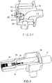
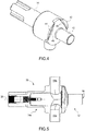
- the figure 3 shows in perspective partially cut connector 10 in the coupled position of the figure 2 and the figure 4 shows another perspective view of the fluid connector still in the coupled position of the figure 2 .
- the two frustoconical surfaces 20 and 24 are of revolution each around their respective axis 22 and 26.
- the connector 10 comprises a set of angular stops.
- the part 14 comprises one or more protuberances 42 and 44 on which bear the flats 46 and 48 produced in the part 12. Any other form of stops is of course possible within the scope of the invention.
- frustoconical surfaces not supported on circles.
- a frustoconical surface comprising at least one flat surface inclined relative to their respective axis makes it possible to control the relative orientation of the parts 12 and 14 around the axes 22 and 26 during the coupling of the connector 10. More generally, any frustoconical surface formed by a portion of cone whose generatrix rests on a non-circular curve makes it possible to control the orientation of the parts 12 and 14 between them.
- frustoconical surfaces of revolution has an advantage due to the symmetry of the fitting around the axis 26. This symmetry keeps the force exerted by the locking mechanism perfectly along the axis 26, avoiding thus any risk of deformation when the effort is exerted.
- realization of frustoconical surfaces of revolution is much easier, in particular by machining than the realization of frustoconical surfaces which would not be of revolution.
- walrus cones whose conicity is close to 5% depending on its dimensions.
- the taper is the tangent of the half-angle at the top of the cone.
- Walrus cones are mainly used in machine tools to ensure the fitting of tools on the spindle of the machine tool.
- the walrus cones ensure very good centering and have significant grip. More precisely, even if the force exerted by the screw 30 is released, the fitting ensures the holding in position of the two parts 12 and 14 coupled.
- cones By way of example, mention may be made of the so-called “metric” cone, which is defined by a taper equal to 5%. Its adhesion is also very important.
- the standard American cone has a taper of 1/24, or 29.16%. The centering is less precise and the grip very weak unlike the walrus or metric cones.
- the connector 10 advantageously comprises one or more gaskets disposed between the two parts 12 and 14.
- the joint or joints are advantageously pressurized by the locking mechanism allowing the fitting of the two frustoconical surfaces 20 and 24.
- the force generated by the locking mechanism being oriented along the axis 26, the joint (s) are then preferably O-rings arranged around of the axis 26.
- the force exerted by the locking mechanism is distributed uniformly over the entire length of the joint (s).
- a circular groove 50 centered around the axis 26 is produced in the part 14 and more precisely, in the flat face 52.
- An O-ring 54 is placed in the groove 50.
- a functional clearance is provided between the face 38 of the part 12 and the face 52 of the part 14 during the fitting of the two frustoconical surfaces 20 and 24.
- the joint 54 is dimensioned to be pressed between the face 38 and the bottom of the groove 50 when the fitting is made. It is also possible to make the groove 50 in the face 38 and to place the seal 54 there, which is then pressed by the flat face 52.
- the seal 54 is arranged on one side of the channel 18. On the other side of the channel 18 a second seal 56 is also disposed in a groove 58 produced in another flat face 60 of the part 14. As for the face 52, the face 60 is perpendicular to the axis 26.
- the part 12 comprises, for its part, a face 62 perpendicular to the axis 22 and intended to come opposite the face 60. As before, a functional clearance is provided between the faces 60 and 62 when the fitting is made in order to allow the compression of the seal 56 during the fitting.
- the seals 54 and 56 are for example elastomeric seals or seals formed by a helical spring with contiguous turns enclosed in a deformable envelope. This type of spring seal is notably known under the brand: "Helicoflex" developed by the company Technetics, whose head office is located in Columbia, in South Carolina (United States of America).
- the figure 5 shows a variant of a fluid connector 70 comprising, as before two parts.
- the fluid connector 70 comprises the part 12 described above and a part 14a which is identical to the part 14 except for the presence of two channels 18a and 18b.
- the two channels 18a and 18b of the part 14a communicate with the channel 16 of the part 12. It is of course possible to have as many channels as necessary in the part 14a.
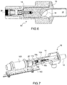
- the figure 6 shows another variant of fluid connector which bears the reference 80.
- the connector 80 is shown in section and in the section plane no channel appears in part 14.
- part 14 does indeed include a channel 18 which s 'extends radially in a plane other than the cutting plane, for example 90 ° from the cutting plane.
- the set of stops allows, in this variant several angular positions of the part 12 relative to the part 14.
- a first angular position fitted with the part 12 relative to the part 14 around the axis 26 allows the communication channels 16 is as shown in the figure 2 and a second fitted angular position makes it possible to interrupt the communication between the two channels 16 and 18 as shown in the figure 6 .
- the second part 14 comprises an extractor 90 which can exert the opposite force.
- the extractor is formed of a threaded ring cooperating with a tapping 92 produced in the counterbore 34 for accommodating the screw 30.
- the extractor can be brought 90 in contact with or in the vicinity of the head 32 of the screw 30. Then, by crossing the bore of the extractor 90, the screw 30 is loosened which, by pressing against the extractor 90 pushes back the part 12. This thrust makes it possible to disengage both frustoconical surfaces 20 and 24.
- the extractor 90 is advantageously configured to make the screw 30 captive. More precisely, the section of the bore of the extractor 90 is smaller than the section of the head 32 of the screw 30. The sections being defined perpendicular to the axis 26. Thus, the head 32 of the screw 30 remains confined in the counterbore 34 by the extractor 90 even in the absence of the part 12.
- the extractor 90 can also be captive. For this purpose, it is possible, for example, to have a circlip 91 at the end of the tapping 92 and making it possible to prevent the extractor 90 from coming out of its tapping 92.
- the ring forming the extractor 90 is pierced along the axis 26.
- the head of the screw 30 includes an imprint 93, for example hexagonal.
- a tool of complementary shape to the imprint 93 can then pass through the extractor 90 to access the imprint 93.
- the operation of the screw 30 allows both its tightening to immobilize the fitting of the two frustoconical surfaces 20 and 24 and its loosening before operation of the extractor 90.
- an elastic element can be placed between the head of the screw 30 and the counterbore 34, for example a helical spring 94.
- a helical spring 94 is placed between the head of the screw 30 and the counterbore 34.
- the spring 94 also has an advantage when tightening the screw 30. From the start of tightening, the spring 94 allows the screw 30 to exert a tensile force on the part 12 tending to keep the two frustoconical surfaces 20 and 24 fitted and therefore the connector coupled.
- the extractor may include an imprint 96 made in its bore.
- a tool adapted to this imprint will make it possible to rotate the extractor 90 in its internal thread and therefore to make it advance to bear on the screw 30 or to make it move back along the axis 26.
- the imprint 96 has larger dimensions than those of the imprint 93 of the screw 30 in order to allow the tool operating the screw 30 to rotate freely in the bore of the extractor 90 without driving it.
- the figure 7 represents the fluid connector 10 with a tool 100 allowing the coupling and uncoupling of the connector 10.
- This tool is advantageous for remote operations. More specifically, the tool 100 allows the operation of the screw 30 and the extractor 90.
- the tool 100 is movable in translation along a rail 102 parallel to the axis 26. The tool 100 can thus be away from the connector 10 or close together to allow the screw 30 and / or the extractor 90 to be maneuvered.
- the tool 100 is supported on the part 12 which may have a grooved outer surface 104 in order to allow the fingers 106 to immobilize the tool 100 in rotation relative to the part 14 and to take up the tightening torque operated by the 'Tool 100.
- any other means of immobilization in rotation about the axis 26 between the tool 100 and the part 14 can of course be implemented.
- the tool has two cavities 108 and 110.
- the cavity 108 is complementary to the cavity 93 of the screw 30.
- the cavity 110 is complementary to the cavity 94 of the extractor 90.
- the operation of the two cavities 108 and 110 is independent.
- the cavity 110 is hollow and is crossed by the cavity 108.
- the two cavities 108 and 110 can rotate independently of one another.
- the imprint 108 can move in translation relative to the imprint 110 to reach the screw 30 whatever its tight or loose position.
- a retraction of the imprint 108 allows the tool 100 to maneuver the extractor 90 without acting on the screw 30.
- the tool 100 allows the two imprints 108 and 110 to be motorized in rotation separately.
- the tool 100 allows motorization in translation along the axis 26 at least the imprint 108.
- the displacement in translation of the imprint 110 can be provided by a motor internal to the tool 100 or by the displacement of the tool 100 along the rail 102.
Landscapes
- Engineering & Computer Science (AREA)
- General Engineering & Computer Science (AREA)
- Mechanical Engineering (AREA)
- Infusion, Injection, And Reservoir Apparatuses (AREA)
- Clamps And Clips (AREA)
- Details Of Connecting Devices For Male And Female Coupling (AREA)
- Quick-Acting Or Multi-Walled Pipe Joints (AREA)
Abstract
L'invention concerne un connecteur fluidique destiné à permettre la circulation d'un fluide et comprenant deux parties (12, 14) configurées pour être accouplées, chacune des parties (12, 14) comprenant un canal (16, 18), les deux canaux (16, 18) communiquant lorsque les deux parties (12, 14) sont accouplées, le fluide étant destiné à être conduit par les deux canaux (16, 18) et un mécanisme de verrouillage (30, 36 ; 31, 33 ; 39, 40) configuré pour prendre appui sur une première (14) des deux parties et pour exercer un effort sur une seconde des deux parties (12) afin d'assurer le maintien en position des deux parties (12, 14) entre elles lorsque les deux parties (12, 14) sont accouplées, le mécanisme de verrouillage (30, 36) traversant une ouverture (37) de la première des deux parties (14).The invention relates to a fluid connector intended to allow the circulation of a fluid and comprising two parts (12, 14) configured to be coupled, each of the parts (12, 14) comprising a channel (16, 18), the two channels (16, 18) communicating when the two parts (12, 14) are coupled, the fluid being intended to be led by the two channels (16, 18) and a locking mechanism (30, 36; 31, 33; 39, 40) configured to rest on a first (14) of the two parts and to exert a force on a second of the two parts (12) in order to maintain the position of the two parts (12, 14) together when the two parts (12, 14) are coupled, the locking mechanism (30, 36) passing through an opening (37) of the first of the two parts (14).
Description
L'invention concerne un connecteur fluidique aisément manoeuvrable. Les réseaux de fluide sous pression sont présents dans de nombreux domaines. Les fluides transportés par ces réseaux peuvent être des gaz, des liquides, des fluides diphasiques. Des particules solides peuvent également être en suspension dans ces fluides. Les réseaux nécessitent des connexions entre différents canaux. Un connecteur fluidique permet de mettre en communication deux canaux ou de réaliser une dérivation dans un canal. Il est possible de réaliser une connexion de façon définitive en collant ou en soudant deux canaux entre eux. Cependant, il peut être nécessaire de permettre le démontage de la connexion par exemple pour raccorder une source de fluide au réseau et permettre le changement de cette source. Plus simplement, pour assurer l'entretien du réseau, le montage et le démontage d'une connexion peuvent être nécessaires.The invention relates to an easily maneuverable fluidic connector. Pressurized fluid networks are present in many areas. The fluids transported by these networks can be gases, liquids, two-phase fluids. Solid particles can also be suspended in these fluids. Networks require connections between different channels. A fluid connector makes it possible to put two channels in communication or to carry out a derivation in a channel. It is possible to make a final connection by gluing or welding two channels together. However, it may be necessary to allow the connection to be dismantled, for example to connect a source of fluid to the network and allow this source to be changed. More simply, to ensure network maintenance, the assembly and disassembly of a connection may be necessary.
Le montage et le démontage d'une connexion peut être réalisé par un opérateur. Cependant, dans certains environnements, l'accès peut être impossible, notamment à cause de l'accessibilité, du fait de la présence de nombreuses tuyauteries enchevêtrées ou à cause d'un environnement dangereux pour l'opérateur, notamment dans le domaine chimique ou nucléaire.The assembly and disassembly of a connection can be carried out by an operator. However, in certain environments, access may be impossible, in particular because of accessibility, because of the presence of numerous tangled pipes or because of an environment dangerous for the operator, in particular in the chemical or nuclear field. .
De façon classique, il est possible de mettre en oeuvre un connecteur raccordant deux canaux alignés. Le verrouillage est réalisé au moyen à bague extérieure à vis. Un tel connecteur est par exemple décrit dans le document
Il est possible de prévoir des connecteurs opérables à distance (télé opérables). On connait par exemple des raccords à baïonnette ou à verrouillage développés par la société Stäubli dont le siège social est situé en Suisse : Poststrasse 5, 8808 Pfäffikon SZ. Les raccords de type RBE TM sont par exemple prévus pour l'environnement nucléaire et un outillage adapté permet de les manipuler à distance. Ce type de raccord n'existe que pour des petits diamètres de canalisation, typiquement inférieurs à 20mm.It is possible to provide remote operable connectors (teleoperable). We know for example bayonet or locking fittings developed by the company Stäubli whose head office is located in Switzerland: Poststrasse 5, 8808 Pfäffikon SZ. RBE TM type fittings are for example intended for the nuclear environment and suitable tools allow them to be handled remotely. This type of fitting exists only for small pipe diameters, typically less than 20mm.
Pour raccorder des canalisations de plus gros diamètres, il est possible de mettre en oeuvre des brides pressant un joint d'étanchéité et maintenues en pression au moyen de plusieurs vis entourant le joint. Il existe également des brides à collier avec un serrage réalisé au moyen d'une chaine entourant les brides. Ce type montage à bride nécessite nécessitent un espace disponible important autour des brides pour le montage et le démontage de celles-ci. De plus, dans le cas où une télé opération est nécessaire, la mise en place d'outils de maintenance peut être compliquée.To connect larger diameter pipes, it is possible to use flanges pressing a gasket and kept under pressure by means of several screws surrounding the seal. There are also collar flanges with a tightening achieved by means of a chain surrounding the flanges. This type of flange mounting requires a large available space around the flanges for mounting and dismounting thereof. In addition, in the case where a remote operation is necessary, the installation of maintenance tools can be complicated.
L'invention vise à pallier tout ou partie des problèmes cités plus haut en proposant un connecteur fluidique aisément connectable et déconnectable.The invention aims to overcome all or part of the problems mentioned above by proposing an easily connectable and disconnectable fluid connector.
A cet effet, l'invention a pour objet un connecteur fluidique destiné à permettre la circulation d'un fluide et comprenant deux parties configurées pour être accouplées, chacune des parties comprenant un canal, les deux canaux communiquant lorsque les deux parties sont accouplées, le fluide étant destiné à être conduit par les deux canaux. Le connecteur fluidique comprend en outre un mécanisme de verrouillage configuré pour prendre appui sur une première des deux parties et pour exercer un effort sur une seconde des deux parties afin d'assurer le maintien en position des deux parties entre elles lorsque les deux parties sont accouplées. Le mécanisme de verrouillage traverse une ouverture de la première partie.To this end, the subject of the invention is a fluid connector intended to allow the circulation of a fluid and comprising two parts configured to be coupled, each of the parts comprising a channel, the two channels communicating when the two parts are coupled, the fluid being intended to be conducted by the two channels. The fluidic connector further comprises a locking mechanism configured to rest on a first of the two parts and to exert a force on a second of the two parts in order to maintain the position of the two parts together when the two parts are coupled. . The locking mechanism passes through an opening of the first part.
Avantageusement, le mécanisme de verrouillage comprend un tirant plein occupant l'ouverture au jeu fonctionnel près.Advantageously, the locking mechanism comprises a solid tie occupying the opening to the nearest functional clearance.
Le connecteur fluidique comprend avantageusement un joint d'étanchéité séparant les canaux de l'ouverture.The fluidic connector advantageously comprises a seal separating the channels from the opening.
Le mécanisme de verrouillage peut comprendre une vis dont une tête s'appuie sur la première partie, la vis traversant l'ouverture et coopérant avec un taraudage réalisé dans une extrémité axiale de la seconde partie.The locking mechanism may comprise a screw, a head of which rests on the first part, the screw passing through the opening and cooperating with a thread produced in an axial end of the second part.
Alternativement, le mécanisme de verrouillage comprend une tige filetée prolongeant la première partie à partir d'une extrémité axiale de la première la première partie, et un écrou coopérant avec la tige filetée et prenant appui sur la première partie.Alternatively, the locking mechanism comprises a threaded rod extending the first part from an axial end of the first the first part, and a nut cooperating with the threaded rod and bearing on the first part.
Une des deux parties peut comprendre une surface tronconique femelle ; l'autre des deux parties peut comprendre une surface tronconique mâle, les deux surfaces tronconiques étant complémentaires, un emmanchement des deux surfaces tronconiques permettant le positionnement des deux parties l'une par rapport à l'autre pour assurer la mise en communication des deux canaux. Le mécanisme de verrouillage est alors configuré pour exercer un effort sur la seconde partie selon un axe de la surface tronconique femelle.One of the two parts may comprise a female frustoconical surface; the other of the two parts may comprise a male frustoconical surface, the two frustoconical surfaces being complementary, a fitting of the two frustoconical surfaces allowing the positioning of the two parts relative to each other to ensure the communication of the two channels. The locking mechanism is then configured to exert a force on the second part along an axis of the female frustoconical surface.
Dans une variante mettant en oeuvre des surfaces tronconiques et une vis, cette dernière peut s'étendre selon l'axe de la surface tronconique femelle et le taraudage est alors réalisé dans une extrémité axiale de la seconde partie, extrémité formant la section de plus petit diamètre de la surface tronconique mâle.In a variant using frustoconical surfaces and a screw, the latter can extend along the axis of the female frustoconical surface and the tapping is then carried out in an axial end of the second part, end forming the section of smaller diameter of the male frustoconical surface.
Dans une variante mettant en oeuvre des surfaces tronconiques et une tige filetée, cette dernière peut s'étendre selon un axe de la surface tronconique mâle à partir d'une extrémité axiale de la seconde partie, extrémité formant la section de plus petit diamètre de la surface tronconique mâle.In a variant using frustoconical surfaces and a threaded rod, the latter can extend along an axis of the male frustoconical surface from an axial end of the second part, end forming the section of smaller diameter of the male tapered surface.
Le mécanisme de verrouillage exerce avantageusement un effort sur le centre de l'extrémité axiale de seconde partie.The locking mechanism advantageously exerts a force on the center of the axial end of the second part.
Les deux surfaces tronconiques possèdent un angle au sommet avantageusement défini pour assurer une auto adhérence des deux surfaces tronconiques une fois emmanchées et la seconde partie comprend un extracteur pouvant exercer un effort opposé à la traction permettant le désaccouplement des deux parties.The two frustoconical surfaces have an angle at the apex advantageously defined to ensure self-adhesion of the two frustoconical surfaces once fitted and the second part comprises an extractor which can exert a force opposite to traction allowing the uncoupling of the two parts.
La vis est avantageusement configurée pour s'appuyer sur l'extracteur afin d'exercer sur la première partie un effort sur la vis par rapport à seconde partie, l'effort étant orienté de façon à découpler les deux surfaces tronconiques.The screw is advantageously configured to rest on the extractor in order to exert a force on the first part on the screw relative to the second part, the force being oriented so as to decouple the two frustoconical surfaces.
La vis peut prendre appui sur la seconde partie par l'intermédiaire d'un élément élastique tendant à éloigner la vis de son appui, après dévissage de la vis du taraudage de la première partie.The screw can bear on the second part by means of an elastic element tending to move the screw away from its support, after unscrewing the screw from the tapping of the first part.
L'extracteur est avantageusement configuré pour rendre la vis imperdable.The extractor is advantageously configured to make the screw captive.
Les deux surfaces tronconiques sont avantageusement de révolution chacune autour d'un axe, les axes des deux surfaces tronconiques étant confondus une fois les deux parties du connecteur accouplées et le connecteur fluidique comprend un ensemble de butées angulaires configuré pour définir au moins une orientation des deux parties autour des axes confondus.The two frustoconical surfaces are advantageously of revolution each around an axis, the axes of the two frustoconical surfaces being merged once the two parts of the connector are coupled and the fluidic connector comprises a set of angular stops configured to define at least one orientation of the two parts around the combined axes.
L'ensemble de butées angulaires peut être configuré pour définir plusieurs orientations angulaires des deux parties autour des axes confondus, une des orientations permettant de mettre en communication les deux canaux, une autre des orientations permettant d'interrompre la communication des deux canaux.The set of angular stops can be configured to define several angular orientations of the two parts around the merged axes, one of the orientations making it possible to put the two channels in communication, another of the orientations making it possible to interrupt the communication of the two channels.
Le connecteur fluidique comprend avantageusement un ou plusieurs joints d'étanchéité disposés entre les deux parties et les moyens de traction sont alors aptes à mettre en pression le ou les joints d'étanchéité.The fluidic connector advantageously comprises one or more seals arranged between the two parts and the traction means are then able to pressurize the seal (s).
L'invention sera mieux comprise et d'autres avantages apparaîtront à la lecture de la description détaillée de modes de réalisation donnés à titre d'exemple, description illustrée par le dessin joint dans lequel :
- les
figures 1a et 1b représentent respectivement et à distance deux parties d'un exemple de connecteur fluidique selon l'invention ; - les
figures 2a ,2b ,2c ,2d ,2e et2f représentent, accouplées, plusieurs variantes d'un connecteur fluidique selon l'invention ; - la
figure 3 représente en perspective coupée partiellement le connecteur fluidique dans la position accouplée de lafigure 2a ; - la
figure 4 représente une autre vue en perspective du connecteur fluidique dans la position accouplée de lafigure 2a ; - les
figures 5 et6 représentent deux variantes d'un connecteur fluidique selon l'invention ; - la
figure 7 représente un connecteur fluidique avec un outil permettant une télé opération de l'accouplement et du désaccouplement du connecteur.
- the
Figures 1a and 1b represent respectively and remotely two parts of an example of a fluid connector according to the invention; - the
figures 2a ,2b ,2c ,2d ,2nd and2 F represent, coupled, several variants of a fluid connector according to the invention; - the
figure 3 shows in perspective partially cut the fluidic connector in the coupled position of thefigure 2a ; - the
figure 4 shows another perspective view of the fluid connector in the coupled position of thefigure 2a ; - the
figures 5 and6 represent two variants of a fluid connector according to the invention; - the
figure 7 represents a fluid connector with a tool allowing a remote operation of the coupling and uncoupling of the connector.
Par souci de clarté, les mêmes éléments porteront les mêmes repères dans les différentes figures.For the sake of clarity, the same elements will have the same references in the different figures.
L'invention se rapporte à un connecteur fluidique 10 comprenant deux parties 12 et 14 pouvant être accouplées. La
Dans la première variante, le positionnement des deux parties 12 et 14 est réalisé au moyen de surfaces tronconiques. Plus précisément, la partie 14 parties comprend une surface tronconique mâle 20 de révolution autour d'un axe 22 et la partie 16 comprend une surface tronconique femelle 24 de révolution autour d'un axe 26. Les deux surfaces tronconiques 20 et 24 sont complémentaires. Lorsque les deux surfaces tronconiques 20 et 24 sont emmanchées l'une dans l'autre, les axes 22 et 26 sont confondus. Les mêmes paramètres géométriques définissent les deux surfaces tronconiques 20 et 22, elles possèdent notamment le même angle au sommet et s'étendent toutes deux sur une distance commune le long de leur axe respectif par rapport à leur sommet qui sont donc confondus une fois emmanchées.In the first variant, the positioning of the two
Lorsque les deux surfaces tronconiques 20 et 24 sont emmanchées l'une dans l'autre les canaux 16 et 18 communiquent dans le connecteur 10.When the two
La partie 14 comprend un mécanisme de verrouillage selon l'axe 26 de la surface tronconique femelle configuré pour exercer un effort sur la partie 12 afin d'assurer le maintien en position des deux parties 12 et 14 entre elles lorsque les deux parties sont accouplées.
Dans l'exemple représenté, le mécanisme de verrouillage comprend une vis 30 s'étendant selon l'axe 26 de la surface tronconique femelle 24. La vis 30 comprend une tête 32 s'appuyant sur un le fond d'un lamage 34 de la seconde partie14. Par ailleurs, un taraudage 36 est réalisé dans la partie 12. Le taraudage 36 s'étend le long de l'axe 22. Le taraudage 36 est réalisé dans une extrémité axiale 38 de la partie 12 formant la section de plus petit diamètre de la surface tronconique 20. Le taraudage 36 est complémentaire du filetage de la vis 30. La vis 30 traverse une ouverture 37 réalisée dans la partie 14. La vis 30 traverse une face plane 52 de la partie 14 formant l'extrémité axiale de plus petit diamètre de la surface tronconique femelle 24. Après emmanchement des deux surfaces tronconiques 20 et 24, le serrage de la vis 30 dans le taraudage 36 permet d'exercer un effort en tirant sur la partie 12 pour verrouiller l'emmanchement des deux surfaces tronconiques 20 et 24 l'une dans l'autre.In the example shown, the locking mechanism comprises a
La
D'autres mécanismes de traction alternatifs au système vis-écrou présenté sur la
La
De façon plus générale, le positionnement réalisé au moyen d'un emmanchement conique permet de supprimer cinq degrés de liberté par obstacle. Le sixième degré de liberté, permettant l'immobilisation des deux parties 12 et 14 entre elles, est supprimé par adhérence lors du serrage du mécanisme de verrouillage. Par ailleurs, dans la variante de la
Dans les différentes variantes décrites précédemment, les mécanismes de verrouillage possèdent un élément traversant l'orifice 37. L'orifice 37 n'est pas utilisé pour la circulation du fluide circulant dans le connecteur. Autrement dit, le fluide ne traverse aucune section de l'orifice 37. Ainsi, la position et la forme de l'orifice 37 est libérée de toute contrainte liée au passage du fluide, notamment en terme de section de passage. L'orifice 37 n'est utilisé que pour faire traverser un tirant, en l'occurrence : la tige 39, la tige filetée 31 ou la vis 30.Le tirant occupe avantageusement l'ouverture 37 au jeu fonctionnel près. Dans les variantes à surfaces tronconiques, le jeu fonctionnel permet au tirant de traverser l'ouverture 37 en tenant compte des tolérances des surfaces tronconiques. Dans la variante de la
Dans les variantes à surfaces tronconiques, le mécanisme de verrouillage exerce avantageusement son effort sur le centre de l'extrémité axiale 38. Ce centrage de l'effort permet de mieux répartir l'effort sur l'ensemble des surfaces tronconiques. Dans la partiel2, le canal 16 s'étend selon l'axe 22. Dans la partie 14, le canal 18 s'étend de façon désaxé par rapport à l'axe 26. Autrement dit, le canal 18 ne traverse pas la face plane 52 ce qui libère de l'espace pour permettre au mécanisme de verrouillage d'exercer son effort par le centre de la face 52. L'effort exercé par le mécanisme de verrouillage est centré par rapport aux surfaces tronconiques 20 et 24. De plus, cet effort peut être exercé par une tige ou une vis n'occupant pas d'espace en périphérie radiale du connecteur fluidique 10.In the variants with frustoconical surfaces, the locking mechanism advantageously exerts its force on the center of the
Le mécanisme de verrouillage peut alternativement comprendre plusieurs tirants permettant de tirer sur la partie 12.The locking mechanism can alternatively comprise several tie rods making it possible to pull on
Dans les variantes représentées sur les
Dans la variante représentée sur les
La
Il est possible de se passer de l'ensemble de butées, par exemple en réalisant des surfaces tronconiques ne s'appuyant pas sur des cercles. Par exemple une surface tronconique comprenant au moins une surface plane inclinée par rapport à leur axe respectif permet de maitriser l'orientation relative des parties 12 et 14 autour des axes 22 et 26 lors de l'accouplement du connecteur 10. De façon plus générale, toute surface tronconique formée d'une portion de cône dont la génératrice s'appuie sur une courbe non circulaire permet de maitriser l'orientation des parties 12 et 14 entre elles.It is possible to do without the set of stops, for example by making frustoconical surfaces not supported on circles. For example, a frustoconical surface comprising at least one flat surface inclined relative to their respective axis makes it possible to control the relative orientation of the
La mise en oeuvre de surfaces tronconiques de révolution présente cependant un avantage due à la symétrie de l'emmanchement autour de l'axe 26. Cette symétrie permet de conserver l'effort exercé par le mécanisme de verrouillage parfaitement selon l'axe 26, évitant ainsi tout risque de déformation lorsque l'effort est exercé. De plus, la réalisation de surfaces tronconiques de révolution est beaucoup plus aisée, notamment par usinage que la réalisation de surfaces tronconiques qui ne seraient pas de révolution.The use of frustoconical surfaces of revolution, however, has an advantage due to the symmetry of the fitting around the
Parmi les surfaces tronconiques de révolution est possible de mettre en oeuvre, des surfaces appelées « cônes morses » dont la conicité est voisine de 5% en fonction de ses dimensions. On rappelle que la conicité est la tangente du demi-angle au sommet du cône. Les cônes morses sont principalement utilisés dans les machines-outils pour assurer l'emmanchement d'outils sur la broche de la machine-outil. Les cônes morses assurent un très bon centrage et présentent une adhérence importante. Plus précisément, même si l'effort exercé par la vis 30 est relâché, l'emmanchement assure le maintien en position des deux parties 12 et 14 accouplées.Among the frustoconical surfaces of revolution is possible to use, surfaces called "walrus cones" whose conicity is close to 5% depending on its dimensions. Remember that the taper is the tangent of the half-angle at the top of the cone. Walrus cones are mainly used in machine tools to ensure the fitting of tools on the spindle of the machine tool. The walrus cones ensure very good centering and have significant grip. More precisely, even if the force exerted by the
Il est bien sûr possible de mettre en oeuvre d'autres types de cônes. A titre d'exemple, on peut citer le cône dit « métrique » qui est, quant à lui, défini par une conicité égale à 5%. Son adhérence est également très importante. Le cône standard américain présente une conicité de 1/24, soit 29,16%. Le centrage est moins précis et l'adhérence très faible contrairement aux cônes morses ou métriques. En mettant en oeuvre le cône standard américain, le maintien de l'effort exercé par la partie 14 sur la partie 12 est nécessaire tant que le connecteur 10 est accouplé. Avec une conicité de l'ordre de 5%, l'effort est utile pour réaliser l'accouplement. Ensuite l'effort peut être relâché.It is of course possible to use other types of cones. By way of example, mention may be made of the so-called “metric” cone, which is defined by a taper equal to 5%. Its adhesion is also very important. The standard American cone has a taper of 1/24, or 29.16%. The centering is less precise and the grip very weak unlike the walrus or metric cones. By implementing the standard American cone, maintaining the force exerted by the
Pour réaliser l'étanchéité de du connecteur 10 et plus précisément de la jonction entre les deux canaux 16 et 18, le connecteur 10 comprend avantageusement un ou plusieurs joints d'étanchéité disposés entre les deux parties 12 et 14. Le ou les joints sont avantageusement mis en pression par le mécanisme de verrouillage permettant l'emmanchement des deux surfaces tronconiques 20 et 24. L'effort généré par le mécanisme de verrouillage étant orienté selon l'axe 26, le ou les joints sont alors de préférence des joints toriques disposés autour de l'axe 26. Ainsi l'effort exercé par le mécanisme de verrouillage est réparti de façon uniforme sur toute la longueur du ou des joints.To seal the
Dans la première variante représentée sur les
On retrouve le joint 54 dans les autres variantes décrites à l'aide des
Le joint 54 est disposé d'un côté du canal 18. De l'autre côté du canal 18 un second joint 56 est également disposé dans une gorge 58 réalisée dans une autre face plane 60 de la partie 14. Comme pour la face 52, la face 60 est perpendiculaire à l'axe 26. La partie 12 comprend, quant à elle, une face 62 perpendiculaire à l'axe 22 et destinée à venir en regard de la face 60. Comme précédemment, un jeu fonctionnel est prévu entre les faces 60 et 62 lorsque l'emmanchement et réalisé afin de permettre la compression du joint 56 lors de l'emmanchement. Les joints 54 et 56 sont par exemple des joints élastomères ou des joints formés d'un ressort hélicoïdal à spires jointives enfermé dans une enveloppe déformable. Ce type de joint à ressort est notamment connu sous la marque : « Helicoflex » développée par la société Technetics dont le siège social est situé à Columbia, en Caroline du Sud (États-Unis d'Amérique).The
La
La
Ces positions angulaires dites ouverte et fermée peuvent également être mise en oeuvre dans la variante de la
Lorsque les deux surfaces tronconiques sont définies pour être adhérentes lorsqu'elles sont emmanchées, une opération particulière est nécessaire pour désaccoupler le connecteur. Plus précisément, il est nécessaire d'exercer sur la partie 12 un effort opposé à celui obtenu par la vis 30 lors de son serrage. Un simple desserrage de la vis 30 ne suffit pas pour permettre le désaccouplement du connecteur du fait de l'adhérence. Cet effort opposé peut être exercé par un outil extérieur. Mais avantageusement, la seconde partie 14 comprend un extracteur 90 pouvant exercer l'effort opposé. Dans les différentes variantes représentées l'extracteur est formé d'une bague filetée coopérant avec un taraudage 92 réalisé dans le lamage 34 permettant d'accueillir la vis 30. Pour exercer l'effort opposé sur la partie 12, on peut amener l'extracteur 90 au contact ou au voisinage de la tête 32 de la vis 30. Ensuite en traversant le perçage de l'extracteur 90, on desserre la vis 30 qui en prenant appui contre l'extracteur 90 repousse la partie 12. Cette poussée permet de désemmancher les deux surfaces tronconiques 20 et 24. Pour éviter que le desserrage de la vis 30 n'entraine celui de l'extracteur 90, il est avantageux d'inverser les pas de la vis 30 et de l'extracteur 90, la vis 30 pouvant avoir un pas à droite et l'extracteur 90 à gauche ou l'inverse. Alternativement, il est possible de desserrer la vis 30 puis de serrer l'extracteur 90 qui pousse sur la tête de la vis 30. Dans les deux cas, la vis 30 prend appui sur l'extracteur 90 pour séparer les deux parties 12 et 14 en exerçant sur la partie 12 un effort de sens opposé à l'effort permettant le verrouillage du connecteur.When the two frustoconical surfaces are defined to be adherent when they are fitted, a special operation is necessary to uncoupling the connector. More specifically, it is necessary to exert on the part 12 a force opposite to that obtained by the
L'extracteur 90 est avantageusement configuré pour rendre la vis 30 imperdable. Plus précisément, la section du perçage de l'extracteur 90 est plus petite que la section de la tête 32 de la vis 30. Les sections étant définies perpendiculairement à l'axe 26. Ainsi, la tête 32 de la vis 30 reste confinée dans le lamage 34 par l'extracteur 90 même en l'absence la partie 12. L'extracteur 90 peut lui aussi être imperdable. A cet effet, on peut par exemple disposer un circlip 91 en extrémité du taraudage 92 et permettant d'éviter que l'extracteur 90 ne sorte de son taraudage 92.The
Pour faciliter la manoeuvre de la vis, la bague formant l'extracteur 90 est percée selon l'axe 26. Au travers du perçage, il est possible d'introduire un outil permettant de manoeuvrer la vis 30. Plus précisément, la tête de la vis 30 comprend une empreinte 93 par exemple hexagonale. Un outil de forme complémentaire à l'empreinte 93 peut alors traverser l'extracteur 90 pour accéder à l'empreinte 93. La manoeuvre de la vis 30 permet à la fois son serrage pour immobiliser l'emmanchement des deux surfaces tronconiques 20 et 24 et son desserrage avant manoeuvre de l'extracteur 90.To facilitate the operation of the screw, the ring forming the
Il est possible d'améliorer la sécurité de fonctionnement de la vis 30. A cet effet, on peut placer entre la tête de la vis 30 et le fond du lamage 34 un élément élastique, comme par exemple un ressort hélicoïdal 94. Ainsi lors du desserrage de la vis 30, la tête de celle-ci tend à s'éloigner de son appui contre le fond du lamage 34. Le ressort 94 présente également un avantage lors du serrage de la vis 30. Dès le début du serrage, le ressort 94 permet à la vis 30 d'exercer un effort de traction sur la partie 12 tendant à maintenir les deux surfaces tronconiques 20 et 24 emmanchées et donc le connecteur accouplé.It is possible to improve the operational safety of the
Pour manoeuvrer l'extracteur 90, celui-ci peut comprendre une empreinte 96 réalisé dans son perçage. Un outil adapté à cette empreinte permettra de faire tourner l'extracteur 90 dans son taraudage et donc de le faire avancer pour prendre appui sur la vis 30 ou de le faire reculer selon l'axe 26. L'empreinte 96 possède des dimensions plus importantes que celles de l'empreinte 93 de la vis 30 afin de permettre à l'outil manoeuvrant la vis 30 de tourner librement dans le perçage de l'extracteur 90 sans l'entrainer.To operate the
La
L'outil 100 prend appui sur la partie 12 qui peut avoir une surface extérieure 104 cannelée afin de permettre à des doigts 106 d'immobiliser l'outil 100 en rotation par rapport à la partie 14 et de reprendre le couple de serrage opéré par l'outil 100. Alternativement, tout autre moyen d'immobilisation en rotation autour de l'axe 26 entre l'outil 100 et la partie 14 peut bien entendu être mis en oeuvre.The
L'outil possède deux empreintes 108 et 110. L'empreinte 108 est complémentaire de l'empreinte 93 de la vis 30. L'empreinte 110 est complémentaire de l'empreinte 94 de l'extracteur 90. La manoeuvre des deux empreintes 108 et 110 est indépendante. L'empreinte 110 est creuse et est traversée par l'empreinte 108. Les deux empreintes 108 et 110 peuvent tourner indépendamment l'une de l'autre. L'empreinte 108 peut se déplacer en translation par rapport à l'empreinte 110 pour atteindre la vis 30 quel que soit sa position serrée ou desserrée. De plus, une rétractation de l'empreinte 108 permet à l'outil 100 de manoeuvrer l'extracteur 90 sans action sur la vis 30. L'outil 100 permet de motoriser séparément en rotation les deux empreintes 108 et 110. L'outil 100 permet de motoriser en translation le long de l'axe 26 au moins l'empreinte 108. Le déplacement en translation de l'empreinte 110 peut être assuré par une motorisation interne à l'outil 100 ou par le déplacement de l'outil 100 le long du rail 102.The tool has two
Claims (15)
Applications Claiming Priority (1)
| Application Number | Priority Date | Filing Date | Title |
|---|---|---|---|
| FR1856740A FR3084131B1 (en) | 2018-07-20 | 2018-07-20 | EASY MANEUVERABLE FLUIDIC CONNECTOR |
Publications (2)
| Publication Number | Publication Date |
|---|---|
| EP3597976A1 true EP3597976A1 (en) | 2020-01-22 |
| EP3597976B1 EP3597976B1 (en) | 2022-03-23 |
Family
ID=63896341
Family Applications (1)
| Application Number | Title | Priority Date | Filing Date |
|---|---|---|---|
| EP19187117.7A Active EP3597976B1 (en) | 2018-07-20 | 2019-07-18 | Easily manoeuvrable fluid connector |
Country Status (3)
| Country | Link |
|---|---|
| US (1) | US11460130B2 (en) |
| EP (1) | EP3597976B1 (en) |
| FR (1) | FR3084131B1 (en) |
Families Citing this family (1)
| Publication number | Priority date | Publication date | Assignee | Title |
|---|---|---|---|---|
| USD996960S1 (en) * | 2022-01-27 | 2023-08-29 | Mullet Tools, LLC | Adapter |
Citations (4)
| Publication number | Priority date | Publication date | Assignee | Title |
|---|---|---|---|---|
| FR644520A (en) * | 1927-03-30 | 1928-10-09 | Westinghouse Freins | Improvements to couplings of metal pipes |
| WO1984000594A1 (en) * | 1982-07-28 | 1984-02-16 | Stig S A Johansson | Articulated pipe coupling |
| WO2012131049A1 (en) | 2011-04-01 | 2012-10-04 | Parker Hannifin Manufacturing Germany GmbH & Co. KG | High pressure-resistant screw connection for pipelines or hose lines having a tapered thread |
| WO2013152396A1 (en) * | 2012-04-12 | 2013-10-17 | Swivelpole Patent Pty Ltd | Swivelling joint |
Family Cites Families (8)
| Publication number | Priority date | Publication date | Assignee | Title |
|---|---|---|---|---|
| US353154A (en) * | 1886-11-23 | Harrison s | ||
| GB1226948A (en) * | 1967-08-10 | 1971-03-31 | ||
| US6260888B1 (en) * | 1998-09-08 | 2001-07-17 | Ford Global Technologies | Manifold attachment |
| US6902200B1 (en) * | 2000-03-28 | 2005-06-07 | Joshua Beadle | Contaminant-resistant pivot joint for outdoor lighting fixture |
| US6456682B1 (en) * | 2001-03-13 | 2002-09-24 | General Electric Company | Core spray sparger T-box attachment with clamp |
| DE102011100852B4 (en) * | 2010-06-10 | 2022-01-27 | Schaeffler Technologies AG & Co. KG | connector |
| US20120001418A1 (en) * | 2010-07-02 | 2012-01-05 | Michel Garcin | Connector |
| US8702130B1 (en) * | 2012-05-04 | 2014-04-22 | Sielc Technologies Corporation | Fitting with improved tube clamping capability |
-
2018
- 2018-07-20 FR FR1856740A patent/FR3084131B1/en not_active Expired - Fee Related
-
2019
- 2019-07-18 EP EP19187117.7A patent/EP3597976B1/en active Active
- 2019-07-18 US US16/516,103 patent/US11460130B2/en active Active
Patent Citations (4)
| Publication number | Priority date | Publication date | Assignee | Title |
|---|---|---|---|---|
| FR644520A (en) * | 1927-03-30 | 1928-10-09 | Westinghouse Freins | Improvements to couplings of metal pipes |
| WO1984000594A1 (en) * | 1982-07-28 | 1984-02-16 | Stig S A Johansson | Articulated pipe coupling |
| WO2012131049A1 (en) | 2011-04-01 | 2012-10-04 | Parker Hannifin Manufacturing Germany GmbH & Co. KG | High pressure-resistant screw connection for pipelines or hose lines having a tapered thread |
| WO2013152396A1 (en) * | 2012-04-12 | 2013-10-17 | Swivelpole Patent Pty Ltd | Swivelling joint |
Also Published As
| Publication number | Publication date |
|---|---|
| FR3084131B1 (en) | 2021-01-01 |
| EP3597976B1 (en) | 2022-03-23 |
| US11460130B2 (en) | 2022-10-04 |
| US20200025313A1 (en) | 2020-01-23 |
| FR3084131A1 (en) | 2020-01-24 |
Similar Documents
| Publication | Publication Date | Title |
|---|---|---|
| EP0027406B1 (en) | Pipe coupling comprising a chain ring | |
| CA1291184C (en) | Quick unlocking connector under load | |
| CH660310A5 (en) | DETACHABLE CONTAINER FILTER. | |
| CA2913861A1 (en) | Device for fixing two parts together | |
| EP2246604B1 (en) | Fluid flow distribuitor or collector device and molding system comprising such device | |
| EP2162663A2 (en) | Connector with improved outer washing | |
| EP3597976B1 (en) | Easily manoeuvrable fluid connector | |
| FR2866094A1 (en) | Mechanical connector for integrating plastic pipe and valve, has ring including two portions, and pipe coupling unit constituted of teeth that are disposed circumferentially on inner side of ring portions | |
| EP0378493B1 (en) | Connecting device with a sealing ring for tubular elements | |
| EP0259209B1 (en) | Device for bringing about a tight connection | |
| EP0124430B1 (en) | Remotely releasable coupling device | |
| WO2013178962A2 (en) | Device and method for fitting two connections at the end of two conduits, in particular in an aircraft | |
| EP0034101B1 (en) | Disconnectable coupling, especially for joining two tubes or pipes | |
| FR2820487A1 (en) | Three-way tap allows take-off from pipe from side or above and has central chamber containing three-way ball with seatings for control handle which has stop fitting against stops on opposite sides of each port | |
| EP1533556A1 (en) | Method of connecting a conduit on a rigid, tubular connecting piece with a swivel nut, and connector according to this method | |
| FR3007495A1 (en) | ASSEMBLY FOR MAKING A THREADED JOINT FOR DRILLING AND OPERATING HYDROCARBON WELLS, THREADED JOINT AND METHOD OF MAKING SAME | |
| FR2664672A1 (en) | Method for assembly by screwing and fluid pipeline connector using this method | |
| FR2749919A1 (en) | CONNECTION DEVICE | |
| WO2024052238A1 (en) | Large-diameter in-line seal comprising a sealing plate | |
| FR2591308A1 (en) | Adjustable adaptor, especially for pipeline elements | |
| FR2536823A1 (en) | Device of the magnetically-controlled valve type comprising control by a link rod. | |
| FR2697610A1 (en) | Guiding device and replaceable end fitting for flexible pipe ends usable at sea. | |
| FR2825774A1 (en) | Coupling for passage of fluid under pressure has nipple shaped to prevent rotation when engaged with matching surfaces in adjoining component | |
| FR3116584A1 (en) | Device for controlling the flow of a fluid with simplified assembly and maintenance | |
| FR2783589A1 (en) | Tube connection method to a body provided with a channel using a deformable clamping screw |
Legal Events
| Date | Code | Title | Description |
|---|---|---|---|
| PUAI | Public reference made under article 153(3) epc to a published international application that has entered the european phase |
Free format text: ORIGINAL CODE: 0009012 |
|
| STAA | Information on the status of an ep patent application or granted ep patent |
Free format text: STATUS: REQUEST FOR EXAMINATION WAS MADE |
|
| 17P | Request for examination filed |
Effective date: 20190718 |
|
| AK | Designated contracting states |
Kind code of ref document: A1 Designated state(s): AL AT BE BG CH CY CZ DE DK EE ES FI FR GB GR HR HU IE IS IT LI LT LU LV MC MK MT NL NO PL PT RO RS SE SI SK SM TR |
|
| AX | Request for extension of the european patent |
Extension state: BA ME |
|
| STAA | Information on the status of an ep patent application or granted ep patent |
Free format text: STATUS: EXAMINATION IS IN PROGRESS |
|
| 17Q | First examination report despatched |
Effective date: 20210315 |
|
| GRAP | Despatch of communication of intention to grant a patent |
Free format text: ORIGINAL CODE: EPIDOSNIGR1 |
|
| STAA | Information on the status of an ep patent application or granted ep patent |
Free format text: STATUS: GRANT OF PATENT IS INTENDED |
|
| INTG | Intention to grant announced |
Effective date: 20211207 |
|
| GRAS | Grant fee paid |
Free format text: ORIGINAL CODE: EPIDOSNIGR3 |
|
| GRAA | (expected) grant |
Free format text: ORIGINAL CODE: 0009210 |
|
| STAA | Information on the status of an ep patent application or granted ep patent |
Free format text: STATUS: THE PATENT HAS BEEN GRANTED |
|
| AK | Designated contracting states |
Kind code of ref document: B1 Designated state(s): AL AT BE BG CH CY CZ DE DK EE ES FI FR GB GR HR HU IE IS IT LI LT LU LV MC MK MT NL NO PL PT RO RS SE SI SK SM TR |
|
| REG | Reference to a national code |
Ref country code: GB Ref legal event code: FG4D Free format text: NOT ENGLISH |
|
| REG | Reference to a national code |
Ref country code: CH Ref legal event code: EP |
|
| REG | Reference to a national code |
Ref country code: IE Ref legal event code: FG4D Free format text: LANGUAGE OF EP DOCUMENT: FRENCH |
|
| REG | Reference to a national code |
Ref country code: DE Ref legal event code: R096 Ref document number: 602019012747 Country of ref document: DE |
|
| REG | Reference to a national code |
Ref country code: AT Ref legal event code: REF Ref document number: 1477664 Country of ref document: AT Kind code of ref document: T Effective date: 20220415 |
|
| REG | Reference to a national code |
Ref country code: LT Ref legal event code: MG9D |
|
| REG | Reference to a national code |
Ref country code: NL Ref legal event code: MP Effective date: 20220323 |
|
| PG25 | Lapsed in a contracting state [announced via postgrant information from national office to epo] |
Ref country code: SE Free format text: LAPSE BECAUSE OF FAILURE TO SUBMIT A TRANSLATION OF THE DESCRIPTION OR TO PAY THE FEE WITHIN THE PRESCRIBED TIME-LIMIT Effective date: 20220323 Ref country code: RS Free format text: LAPSE BECAUSE OF FAILURE TO SUBMIT A TRANSLATION OF THE DESCRIPTION OR TO PAY THE FEE WITHIN THE PRESCRIBED TIME-LIMIT Effective date: 20220323 Ref country code: NO Free format text: LAPSE BECAUSE OF FAILURE TO SUBMIT A TRANSLATION OF THE DESCRIPTION OR TO PAY THE FEE WITHIN THE PRESCRIBED TIME-LIMIT Effective date: 20220623 Ref country code: LT Free format text: LAPSE BECAUSE OF FAILURE TO SUBMIT A TRANSLATION OF THE DESCRIPTION OR TO PAY THE FEE WITHIN THE PRESCRIBED TIME-LIMIT Effective date: 20220323 Ref country code: HR Free format text: LAPSE BECAUSE OF FAILURE TO SUBMIT A TRANSLATION OF THE DESCRIPTION OR TO PAY THE FEE WITHIN THE PRESCRIBED TIME-LIMIT Effective date: 20220323 Ref country code: BG Free format text: LAPSE BECAUSE OF FAILURE TO SUBMIT A TRANSLATION OF THE DESCRIPTION OR TO PAY THE FEE WITHIN THE PRESCRIBED TIME-LIMIT Effective date: 20220623 |
|
| REG | Reference to a national code |
Ref country code: AT Ref legal event code: MK05 Ref document number: 1477664 Country of ref document: AT Kind code of ref document: T Effective date: 20220323 |
|
| PG25 | Lapsed in a contracting state [announced via postgrant information from national office to epo] |
Ref country code: LV Free format text: LAPSE BECAUSE OF FAILURE TO SUBMIT A TRANSLATION OF THE DESCRIPTION OR TO PAY THE FEE WITHIN THE PRESCRIBED TIME-LIMIT Effective date: 20220323 Ref country code: GR Free format text: LAPSE BECAUSE OF FAILURE TO SUBMIT A TRANSLATION OF THE DESCRIPTION OR TO PAY THE FEE WITHIN THE PRESCRIBED TIME-LIMIT Effective date: 20220624 Ref country code: FI Free format text: LAPSE BECAUSE OF FAILURE TO SUBMIT A TRANSLATION OF THE DESCRIPTION OR TO PAY THE FEE WITHIN THE PRESCRIBED TIME-LIMIT Effective date: 20220323 |
|
| PG25 | Lapsed in a contracting state [announced via postgrant information from national office to epo] |
Ref country code: NL Free format text: LAPSE BECAUSE OF FAILURE TO SUBMIT A TRANSLATION OF THE DESCRIPTION OR TO PAY THE FEE WITHIN THE PRESCRIBED TIME-LIMIT Effective date: 20220323 |
|
| PG25 | Lapsed in a contracting state [announced via postgrant information from national office to epo] |
Ref country code: SM Free format text: LAPSE BECAUSE OF FAILURE TO SUBMIT A TRANSLATION OF THE DESCRIPTION OR TO PAY THE FEE WITHIN THE PRESCRIBED TIME-LIMIT Effective date: 20220323 Ref country code: SK Free format text: LAPSE BECAUSE OF FAILURE TO SUBMIT A TRANSLATION OF THE DESCRIPTION OR TO PAY THE FEE WITHIN THE PRESCRIBED TIME-LIMIT Effective date: 20220323 Ref country code: RO Free format text: LAPSE BECAUSE OF FAILURE TO SUBMIT A TRANSLATION OF THE DESCRIPTION OR TO PAY THE FEE WITHIN THE PRESCRIBED TIME-LIMIT Effective date: 20220323 Ref country code: PT Free format text: LAPSE BECAUSE OF FAILURE TO SUBMIT A TRANSLATION OF THE DESCRIPTION OR TO PAY THE FEE WITHIN THE PRESCRIBED TIME-LIMIT Effective date: 20220725 Ref country code: ES Free format text: LAPSE BECAUSE OF FAILURE TO SUBMIT A TRANSLATION OF THE DESCRIPTION OR TO PAY THE FEE WITHIN THE PRESCRIBED TIME-LIMIT Effective date: 20220323 Ref country code: EE Free format text: LAPSE BECAUSE OF FAILURE TO SUBMIT A TRANSLATION OF THE DESCRIPTION OR TO PAY THE FEE WITHIN THE PRESCRIBED TIME-LIMIT Effective date: 20220323 Ref country code: CZ Free format text: LAPSE BECAUSE OF FAILURE TO SUBMIT A TRANSLATION OF THE DESCRIPTION OR TO PAY THE FEE WITHIN THE PRESCRIBED TIME-LIMIT Effective date: 20220323 Ref country code: AT Free format text: LAPSE BECAUSE OF FAILURE TO SUBMIT A TRANSLATION OF THE DESCRIPTION OR TO PAY THE FEE WITHIN THE PRESCRIBED TIME-LIMIT Effective date: 20220323 |
|
| PG25 | Lapsed in a contracting state [announced via postgrant information from national office to epo] |
Ref country code: PL Free format text: LAPSE BECAUSE OF FAILURE TO SUBMIT A TRANSLATION OF THE DESCRIPTION OR TO PAY THE FEE WITHIN THE PRESCRIBED TIME-LIMIT Effective date: 20220323 Ref country code: IS Free format text: LAPSE BECAUSE OF FAILURE TO SUBMIT A TRANSLATION OF THE DESCRIPTION OR TO PAY THE FEE WITHIN THE PRESCRIBED TIME-LIMIT Effective date: 20220723 Ref country code: AL Free format text: LAPSE BECAUSE OF FAILURE TO SUBMIT A TRANSLATION OF THE DESCRIPTION OR TO PAY THE FEE WITHIN THE PRESCRIBED TIME-LIMIT Effective date: 20220323 |
|
| REG | Reference to a national code |
Ref country code: DE Ref legal event code: R097 Ref document number: 602019012747 Country of ref document: DE |
|
| PLBE | No opposition filed within time limit |
Free format text: ORIGINAL CODE: 0009261 |
|
| STAA | Information on the status of an ep patent application or granted ep patent |
Free format text: STATUS: NO OPPOSITION FILED WITHIN TIME LIMIT |
|
| PG25 | Lapsed in a contracting state [announced via postgrant information from national office to epo] |
Ref country code: DK Free format text: LAPSE BECAUSE OF FAILURE TO SUBMIT A TRANSLATION OF THE DESCRIPTION OR TO PAY THE FEE WITHIN THE PRESCRIBED TIME-LIMIT Effective date: 20220323 |
|
| PG25 | Lapsed in a contracting state [announced via postgrant information from national office to epo] |
Ref country code: MC Free format text: LAPSE BECAUSE OF FAILURE TO SUBMIT A TRANSLATION OF THE DESCRIPTION OR TO PAY THE FEE WITHIN THE PRESCRIBED TIME-LIMIT Effective date: 20220323 |
|
| REG | Reference to a national code |
Ref country code: CH Ref legal event code: PL |
|
| 26N | No opposition filed |
Effective date: 20230102 |
|
| REG | Reference to a national code |
Ref country code: BE Ref legal event code: MM Effective date: 20220731 |
|
| PG25 | Lapsed in a contracting state [announced via postgrant information from national office to epo] |
Ref country code: LU Free format text: LAPSE BECAUSE OF NON-PAYMENT OF DUE FEES Effective date: 20220718 Ref country code: LI Free format text: LAPSE BECAUSE OF NON-PAYMENT OF DUE FEES Effective date: 20220731 Ref country code: CH Free format text: LAPSE BECAUSE OF NON-PAYMENT OF DUE FEES Effective date: 20220731 |
|
| PG25 | Lapsed in a contracting state [announced via postgrant information from national office to epo] |
Ref country code: SI Free format text: LAPSE BECAUSE OF FAILURE TO SUBMIT A TRANSLATION OF THE DESCRIPTION OR TO PAY THE FEE WITHIN THE PRESCRIBED TIME-LIMIT Effective date: 20220323 Ref country code: BE Free format text: LAPSE BECAUSE OF NON-PAYMENT OF DUE FEES Effective date: 20220731 |
|
| PG25 | Lapsed in a contracting state [announced via postgrant information from national office to epo] |
Ref country code: IE Free format text: LAPSE BECAUSE OF NON-PAYMENT OF DUE FEES Effective date: 20220718 |
|
| PGFP | Annual fee paid to national office [announced via postgrant information from national office to epo] |
Ref country code: IT Payment date: 20230731 Year of fee payment: 5 Ref country code: GB Payment date: 20230724 Year of fee payment: 5 |
|
| PGFP | Annual fee paid to national office [announced via postgrant information from national office to epo] |
Ref country code: FR Payment date: 20230720 Year of fee payment: 5 Ref country code: DE Payment date: 20230720 Year of fee payment: 5 |
|
| PG25 | Lapsed in a contracting state [announced via postgrant information from national office to epo] |
Ref country code: HU Free format text: LAPSE BECAUSE OF FAILURE TO SUBMIT A TRANSLATION OF THE DESCRIPTION OR TO PAY THE FEE WITHIN THE PRESCRIBED TIME-LIMIT; INVALID AB INITIO Effective date: 20190718 |
|
| PG25 | Lapsed in a contracting state [announced via postgrant information from national office to epo] |
Ref country code: MK Free format text: LAPSE BECAUSE OF FAILURE TO SUBMIT A TRANSLATION OF THE DESCRIPTION OR TO PAY THE FEE WITHIN THE PRESCRIBED TIME-LIMIT Effective date: 20220323 Ref country code: CY Free format text: LAPSE BECAUSE OF FAILURE TO SUBMIT A TRANSLATION OF THE DESCRIPTION OR TO PAY THE FEE WITHIN THE PRESCRIBED TIME-LIMIT Effective date: 20220323 |
|
| PG25 | Lapsed in a contracting state [announced via postgrant information from national office to epo] |
Ref country code: TR Free format text: LAPSE BECAUSE OF FAILURE TO SUBMIT A TRANSLATION OF THE DESCRIPTION OR TO PAY THE FEE WITHIN THE PRESCRIBED TIME-LIMIT Effective date: 20220323 |