EP0262473B1 - Optisches Kabel mit Beugungsmechanismus - Google Patents
Optisches Kabel mit Beugungsmechanismus Download PDFInfo
- Publication number
- EP0262473B1 EP0262473B1 EP87113124A EP87113124A EP0262473B1 EP 0262473 B1 EP0262473 B1 EP 0262473B1 EP 87113124 A EP87113124 A EP 87113124A EP 87113124 A EP87113124 A EP 87113124A EP 0262473 B1 EP0262473 B1 EP 0262473B1
- Authority
- EP
- European Patent Office
- Prior art keywords
- optical
- tube member
- fibre
- optical cable
- end portion
- Prior art date
- Legal status (The legal status is an assumption and is not a legal conclusion. Google has not performed a legal analysis and makes no representation as to the accuracy of the status listed.)
- Expired - Lifetime
Links
Images

Classifications
-
- A—HUMAN NECESSITIES
- A61—MEDICAL OR VETERINARY SCIENCE; HYGIENE
- A61B—DIAGNOSIS; SURGERY; IDENTIFICATION
- A61B1/00—Instruments for performing medical examinations of the interior of cavities or tubes of the body by visual or photographical inspection, e.g. endoscopes; Illuminating arrangements therefor
- A61B1/005—Flexible endoscopes
- A61B1/0051—Flexible endoscopes with controlled bending of insertion part
-
- G—PHYSICS
- G02—OPTICS
- G02B—OPTICAL ELEMENTS, SYSTEMS OR APPARATUS
- G02B23/00—Telescopes, e.g. binoculars; Periscopes; Instruments for viewing the inside of hollow bodies; Viewfinders; Optical aiming or sighting devices
- G02B23/24—Instruments or systems for viewing the inside of hollow bodies, e.g. fibrescopes
- G02B23/26—Instruments or systems for viewing the inside of hollow bodies, e.g. fibrescopes using light guides
-
- G—PHYSICS
- G02—OPTICS
- G02B—OPTICAL ELEMENTS, SYSTEMS OR APPARATUS
- G02B6/00—Light guides; Structural details of arrangements comprising light guides and other optical elements, e.g. couplings
- G02B6/44—Mechanical structures for providing tensile strength and external protection for fibres, e.g. optical transmission cables
- G02B6/4401—Optical cables
- G02B6/4415—Cables for special applications
-
- G—PHYSICS
- G02—OPTICS
- G02B—OPTICAL ELEMENTS, SYSTEMS OR APPARATUS
- G02B6/00—Light guides; Structural details of arrangements comprising light guides and other optical elements, e.g. couplings
- G02B6/44—Mechanical structures for providing tensile strength and external protection for fibres, e.g. optical transmission cables
- G02B6/4401—Optical cables
- G02B6/4429—Means specially adapted for strengthening or protecting the cables
Definitions
- This invention relates to a cable with a bending mechanism, and more particularly to a cable usefully applicable to an optical fibre sensor such as a medical or industrial endoscope or to a laser beam surgical catheter.
- the optical fibre sensor such as a medical or industrial endoscope
- an optical fibre sensor shown in Fig. 1 has been developed.
- a plurality of knuckle rings 6 are provided to encircle the fibre sensor body 8.
- the knuckle rings 6 come into contact with one another at protruded support portions 7 provided in the centre portions of the rings 6.
- Several operating wires 5 are provided at the peripheral portions of the knuckle rings 6 in a symmetrical manner. According to such a structure of the optical fibre sensor, be tightening or pulling up one or ones of the wires 5 but extending other one or ones of the wires, the end portion of the fibre is bent to let the image pickup portion at the end portion thereof face in a desired direction.
- the conventional optical fibre sensor having the above-described structure has such a problem that the fibre sensor as a whole is made thick by the use of the knuckle rings 6. To the contrary, recently it becomes possible to produce a very long but very thin image fibre which is used as a body of the optical fibre sensor.
- a fibrescope is known from document EP-A-164623 wherein, instead of knuckle rings encircling the fibre sensor body, a flexible tube member is used.
- operating wires still have to be threaded through the tube via cylindrical casted sections provided at the tips of the fibrescope and although there is no increase in the thickness of the fibrescope and there is a reduction in the weight of the bending portion nevertheless, the arrangement is complicated with the use of operating wires and there is still a need for a smaller sized device as well as more flexibility and the ease of use.
- An object of the present invention is to solve the above-described problems of the conventional optical fibre sensor. That is, the object of the present invention is to provide an optical fibre sensor with a bending mechanism which has a small diameter and a relatively simple structure and is operable to bend at its tip end.
- an optical cable of the present invention comprises: An optical cable, comprising: a flexible tube member; an optical fibre sensor body having an optical fibre and a flexible coating film covering an external circumferential wall portion of the fibre, the sensor body being coaxially arranged in the tube member such that the coating film faces an internal circumferential wall portion of the tube member, characterised in that a fluid is provided in between the coating film and the internal circumferential wall portion of the tube member, and in that the tube member is bent at an end portion and comprises a sealing means at the end portion for sealing the fluid in between the coating film and the tube member so that when pressure is applied to the fluid the degree of bending (a) of the tube member at the end portion is changed.
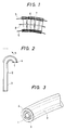
- FIG. 2 is a vertically sectional view outlining the optical cable with bending mechanism of an embodiment of the present invention.
- FIG. 3 is a perspective view showing a tip end portion of the optical cable of FIG. 2.
- the optical fiber sensor body 1 is inserted into a tube 3 having excellent bending characteristic or flexibility made of plastic such as polyethylene, rubber such as silicone rubber, or the like.
- the optical fiber sensor 1 is previously bent at its end portion with a desired radius of curvature, so that the tube 3 is in a shape indicated by a solid line in FIG. 2.
- a space 2 is filled with liquid or gas, since the space 2 is closed at its tip end with a stopper or plug 4, the internal pressure of the space 2 is increased to thereby bend the tube 3 and stopper 4 in a direction a in FIG. 2.
- the degree of bending of the fiber sensor 1 is changeable with controlling the internal pressure of the space 2.
- the above description is made to an embodiment of the present invention applied to an optical fiber sensor having an image sensor as its body.
- the above-described bending mechanism is further applicable to an optical cable in which an energy fiber made of AgBr, AgCl which transmit CO2 laser beam therethrough, or the like is inserted with or without the image fiber. If the bending mechanism of the present invention is applied to the end portion of the cable having such an energy transmitting fiber therein, it becomes possible to freely change the laser beam irradiation direction so that it makes possible to apply the laser beam to any affected part on a body as a laser beam medical treatment.
- FIG. 4 shows one example of the optical fiber cable of the embodiment of the present invention used as a medical endoscope.
- FIG. 5 shows the end portion of the optical fiber cable of FIG. 4.
- a tube made of polyurethane resin having stainless braided wires therein is used for the tube 3.
- the optical fiber sensor 1 comprises a group of elemental fibers coated with polyurethane resin 14.
- the group of elemental fibers includes an image transmitting bundle fiber 10, an objective lens group 11 provided at the end portion of the image transmitting bundle fiber 10, an illumination light transmitting fiber 12 and a laser beam transmission fiber 13, as shown in FIG. 5.
- the stopper 4 made of polyurethan resin is provided at the end of the optical fiber cable.
- the illumination light transmission fiber 12 is made of silicone resin.
- the image transmission bundle fiber 10 comprises a bundle of three thousand elemental fibers of multi-compound glass, at the end portion of which a lens 11 made of optical glass is provided and held at an optical position with a holding sleeve.
- As the laser beam transmission fiber 13 an optical fiber of pure quartz series having a core diameter of 200 micron is used.
- the optical cable of the present invention is made simple in construction and has a small diameter.
Landscapes
- Physics & Mathematics (AREA)
- Optics & Photonics (AREA)
- General Physics & Mathematics (AREA)
- Health & Medical Sciences (AREA)
- Life Sciences & Earth Sciences (AREA)
- Surgery (AREA)
- Engineering & Computer Science (AREA)
- Medical Informatics (AREA)
- Radiology & Medical Imaging (AREA)
- Nuclear Medicine, Radiotherapy & Molecular Imaging (AREA)
- Biophysics (AREA)
- Biomedical Technology (AREA)
- Heart & Thoracic Surgery (AREA)
- Pathology (AREA)
- Molecular Biology (AREA)
- Animal Behavior & Ethology (AREA)
- General Health & Medical Sciences (AREA)
- Public Health (AREA)
- Veterinary Medicine (AREA)
- Astronomy & Astrophysics (AREA)
- Instruments For Viewing The Inside Of Hollow Bodies (AREA)
- Endoscopes (AREA)
Claims (5)
- Ein optisches Kabel, umfassend:
ein biegbares Rohrelement (3);
einen optischen Fasersensorkörper (1), der eine optische Faser (10; 12; 13) und eine biegbare Beschichtungsschicht (14) aufweist, die einen äußeren Umfangswandbereich der genannten Faser (10; 12; 13) überdeckt, wobei der genannte Sensorkörper koaxial in dem genannten Rohrelement (3) so angeordnet ist, daß die genannte Beschichtungsschicht (14) zu einem inneren Umfangswandbereich des genannten Rohrelements (3) weist,
dadurch gekennzeichnet, daß
ein Fluid zwischen der genannten Beschichtungsschicht (14) und dem genannten inneren Umfangswandbereich des genannten Rohrelements (3) vorgesehen ist, und daß
das genannte Rohrelement (3) an einem Endabschnitt gebogen ist und eine Abdichteinrichtung an dem genannten Endabschnitt umfaßt, um das genannte Fluid zwischen der genannten Beschichtungsschicht (14) und dem genannten Rohrelement (3) so abzudichten, daß, wenn ein Druck auf das genannte Fluid ausgeübt wird, der Beugungsgrad (a) des genannten Rohrelements an dem genannten Endabschnitt geändert wird. - Ein optisches Kabel gemäß Anspruch 1, bei dem die genannte Abdichteinrichtung ein Stopfenelement (4) umfaßt.
- Ein optisches Kabel gemäß Anspruch 1, bei dem der genannte optische Fasersensorkörper (1) einen Bildübertragungsabschnitt (10, 11) und einen Beleuchtungsstrahl-Übertragungsabschnitt (13) hat.
- Ein optisches Kabel gemäß Anspruch 1 oder 3, bei dem die genannte optische Faser aus einer Bildfaser und/oder einer Energiefaser ausgewählt ist.
- Ein optisches Kabel gemäß Anspruch 1, bei dem das Fluid aus Flüssigkeit und Gas ausgewählt ist.
Applications Claiming Priority (2)
| Application Number | Priority Date | Filing Date | Title |
|---|---|---|---|
| JP211213/86 | 1986-09-08 | ||
| JP61211213A JPS6365413A (ja) | 1986-09-08 | 1986-09-08 | 屈曲機構を備えた光学的ケ−ブル |
Publications (3)
| Publication Number | Publication Date |
|---|---|
| EP0262473A2 EP0262473A2 (de) | 1988-04-06 |
| EP0262473A3 EP0262473A3 (en) | 1989-07-19 |
| EP0262473B1 true EP0262473B1 (de) | 1993-12-15 |
Family
ID=16602183
Family Applications (1)
| Application Number | Title | Priority Date | Filing Date |
|---|---|---|---|
| EP87113124A Expired - Lifetime EP0262473B1 (de) | 1986-09-08 | 1987-09-08 | Optisches Kabel mit Beugungsmechanismus |
Country Status (7)
| Country | Link |
|---|---|
| US (1) | US4826281A (de) |
| EP (1) | EP0262473B1 (de) |
| JP (1) | JPS6365413A (de) |
| KR (1) | KR900008475B1 (de) |
| AU (1) | AU595063B2 (de) |
| CA (1) | CA1300942C (de) |
| DE (1) | DE3788484T2 (de) |
Families Citing this family (6)
| Publication number | Priority date | Publication date | Assignee | Title |
|---|---|---|---|---|
| US5018506A (en) * | 1990-06-18 | 1991-05-28 | Welch Allyn, Inc. | Fluid controlled biased bending neck |
| WO1999009879A1 (en) * | 1997-08-27 | 1999-03-04 | Pinotage, L.L.C. | Controllable multi-directional surgical positioning device |
| KR100319537B1 (ko) * | 2000-04-04 | 2002-01-16 | 강신원 | 열광학 폴리머 평면도파로의 소산장결합을 이용한광섬유형 온도센서 |
| DE10351549A1 (de) * | 2003-11-03 | 2005-06-02 | Westfaliasurge Gmbh | Einheit zur Lageänderung einer Leitung, insbesondere einer Milchleitung |
| WO2011092937A1 (ja) * | 2010-01-29 | 2011-08-04 | オリンパスメディカルシステムズ株式会社 | 挿入機器、内視鏡 |
| JP5989666B2 (ja) * | 2011-01-05 | 2016-09-07 | バル・イラン・ユニバーシティBar Ilan University | 多芯ファイバを使用する撮像システム |
Family Cites Families (9)
| Publication number | Priority date | Publication date | Assignee | Title |
|---|---|---|---|---|
| US3583393A (en) * | 1967-12-26 | 1971-06-08 | Olympus Optical Co | Bendable tube assembly |
| DE2835331C3 (de) * | 1978-08-11 | 1981-11-05 | Siemens AG, 1000 Berlin und 8000 München | Endoskop mit elektrischer Bildübertragung |
| US4470407A (en) * | 1982-03-11 | 1984-09-11 | Laserscope, Inc. | Endoscopic device |
| US4530078A (en) * | 1982-06-11 | 1985-07-16 | Nicholas Lagakos | Microbending fiber optic acoustic sensor |
| US4575185A (en) * | 1983-08-01 | 1986-03-11 | Combustion Engineering, Inc. | System for a fiber optic cable for remote inspection of internal structure of a nuclear steam generator |
| GB8413058D0 (en) * | 1984-05-22 | 1984-06-27 | Minvade Ltd | Endoscopes |
| JPS60253428A (ja) * | 1984-05-30 | 1985-12-14 | 住友電気工業株式会社 | 屈曲機構付フアイバスコ−プ |
| JPS61103430A (ja) * | 1984-10-26 | 1986-05-21 | オリンパス光学工業株式会社 | 内視鏡 |
| US4735501A (en) * | 1986-04-21 | 1988-04-05 | Identechs Corporation | Method and apparatus for fluid propelled borescopes |
-
1986
- 1986-09-08 JP JP61211213A patent/JPS6365413A/ja active Pending
-
1987
- 1987-09-05 KR KR1019870009814A patent/KR900008475B1/ko not_active Expired
- 1987-09-08 EP EP87113124A patent/EP0262473B1/de not_active Expired - Lifetime
- 1987-09-08 AU AU78168/87A patent/AU595063B2/en not_active Ceased
- 1987-09-08 CA CA000546344A patent/CA1300942C/en not_active Expired - Lifetime
- 1987-09-08 US US07/093,658 patent/US4826281A/en not_active Expired - Fee Related
- 1987-09-08 DE DE87113124T patent/DE3788484T2/de not_active Expired - Fee Related
Also Published As
| Publication number | Publication date |
|---|---|
| AU7816887A (en) | 1988-03-10 |
| US4826281A (en) | 1989-05-02 |
| KR880004335A (ko) | 1988-06-07 |
| CA1300942C (en) | 1992-05-19 |
| KR900008475B1 (ko) | 1990-11-22 |
| EP0262473A3 (en) | 1989-07-19 |
| DE3788484D1 (de) | 1994-01-27 |
| DE3788484T2 (de) | 1994-03-31 |
| AU595063B2 (en) | 1990-03-22 |
| JPS6365413A (ja) | 1988-03-24 |
| EP0262473A2 (de) | 1988-04-06 |
Similar Documents
| Publication | Publication Date | Title |
|---|---|---|
| US4708434A (en) | Fiberscope with bending mechanism | |
| US5577992A (en) | Bendable portion of endoscope | |
| EP0113225B1 (de) | Verfahren zur Beobachtung eines Bildes | |
| US4899732A (en) | Miniscope | |
| US5299562A (en) | Endoscope having a controllable distal end piece | |
| EP0027185B1 (de) | Schutzumhüllung für den biegsamen Abschnitt eines Endoskops | |
| US5630788A (en) | Endoscope with curved end image guide | |
| US4826280A (en) | Grooved optical transmission channel | |
| CA1290734C (en) | Fiberscope | |
| US5073048A (en) | Optical fiber bundle | |
| EP0262473B1 (de) | Optisches Kabel mit Beugungsmechanismus | |
| US5210814A (en) | High resolution optical device with rigid fiber optic bundle | |
| EP0435506A2 (de) | Infrarot aussendendes System mit Zieleinrichtung | |
| JPS5930504A (ja) | 内視鏡用光学繊維束の外装装置 | |
| JP2949653B2 (ja) | 硬性イメ−ジスコ−プ | |
| JPH0434496Y2 (de) | ||
| JP3052409U (ja) | レーザ装置 | |
| JPH0753041Y2 (ja) | 内視鏡の光学繊維束 | |
| JPH0142085Y2 (de) | ||
| SU1616597A1 (ru) | Эндоскоп | |
| JPH0627900B2 (ja) | ケーブルの屈曲機構 | |
| JPH02135313A (ja) | 内視鏡スコープ | |
| JPH0521224U (ja) | 内視鏡の光学繊維束 | |
| JPS592003A (ja) | フアイバ−型光導波路の保護層 | |
| JPS63194630A (ja) | 長尺体の屈曲機構 |
Legal Events
| Date | Code | Title | Description |
|---|---|---|---|
| PUAI | Public reference made under article 153(3) epc to a published international application that has entered the european phase |
Free format text: ORIGINAL CODE: 0009012 |
|
| AK | Designated contracting states |
Kind code of ref document: A2 Designated state(s): DE FR GB IT NL SE |
|
| PUAL | Search report despatched |
Free format text: ORIGINAL CODE: 0009013 |
|
| AK | Designated contracting states |
Kind code of ref document: A3 Designated state(s): DE FR GB IT NL SE |
|
| 17P | Request for examination filed |
Effective date: 19890914 |
|
| 17Q | First examination report despatched |
Effective date: 19911007 |
|
| GRAA | (expected) grant |
Free format text: ORIGINAL CODE: 0009210 |
|
| AK | Designated contracting states |
Kind code of ref document: B1 Designated state(s): DE FR GB IT NL SE |
|
| REF | Corresponds to: |
Ref document number: 3788484 Country of ref document: DE Date of ref document: 19940127 |
|
| ITF | It: translation for a ep patent filed | ||
| ET | Fr: translation filed | ||
| PLBE | No opposition filed within time limit |
Free format text: ORIGINAL CODE: 0009261 |
|
| STAA | Information on the status of an ep patent application or granted ep patent |
Free format text: STATUS: NO OPPOSITION FILED WITHIN TIME LIMIT |
|
| 26N | No opposition filed | ||
| EAL | Se: european patent in force in sweden |
Ref document number: 87113124.9 |
|
| PGFP | Annual fee paid to national office [announced via postgrant information from national office to epo] |
Ref country code: GB Payment date: 19950829 Year of fee payment: 9 |
|
| PGFP | Annual fee paid to national office [announced via postgrant information from national office to epo] |
Ref country code: FR Payment date: 19950911 Year of fee payment: 9 |
|
| PGFP | Annual fee paid to national office [announced via postgrant information from national office to epo] |
Ref country code: SE Payment date: 19950918 Year of fee payment: 9 Ref country code: DE Payment date: 19950918 Year of fee payment: 9 |
|
| PGFP | Annual fee paid to national office [announced via postgrant information from national office to epo] |
Ref country code: NL Payment date: 19950922 Year of fee payment: 9 |
|
| REG | Reference to a national code |
Ref country code: GB Ref legal event code: 746 Effective date: 19960319 |
|
| PG25 | Lapsed in a contracting state [announced via postgrant information from national office to epo] |
Ref country code: GB Effective date: 19960908 |
|
| PG25 | Lapsed in a contracting state [announced via postgrant information from national office to epo] |
Ref country code: SE Effective date: 19960909 |
|
| PG25 | Lapsed in a contracting state [announced via postgrant information from national office to epo] |
Ref country code: FR Effective date: 19960930 |
|
| REG | Reference to a national code |
Ref country code: FR Ref legal event code: D9 Free format text: CORRECTION |
|
| PG25 | Lapsed in a contracting state [announced via postgrant information from national office to epo] |
Ref country code: NL Effective date: 19970401 |
|
| GBPC | Gb: european patent ceased through non-payment of renewal fee |
Effective date: 19960908 |
|
| NLV4 | Nl: lapsed or anulled due to non-payment of the annual fee |
Effective date: 19970401 |
|
| PG25 | Lapsed in a contracting state [announced via postgrant information from national office to epo] |
Ref country code: DE Effective date: 19970603 |
|
| EUG | Se: european patent has lapsed |
Ref document number: 87113124.9 |
|
| REG | Reference to a national code |
Ref country code: FR Ref legal event code: ST |
|
| REG | Reference to a national code |
Ref country code: FR Ref legal event code: ST |
|
| PG25 | Lapsed in a contracting state [announced via postgrant information from national office to epo] |
Ref country code: IT Free format text: LAPSE BECAUSE OF NON-PAYMENT OF DUE FEES;WARNING: LAPSES OF ITALIAN PATENTS WITH EFFECTIVE DATE BEFORE 2007 MAY HAVE OCCURRED AT ANY TIME BEFORE 2007. THE CORRECT EFFECTIVE DATE MAY BE DIFFERENT FROM THE ONE RECORDED. Effective date: 20050908 |