EP0259443B1 - Verfahren und vorrichtung zur regelung eines fahrzeuges - Google Patents
Verfahren und vorrichtung zur regelung eines fahrzeuges Download PDFInfo
- Publication number
- EP0259443B1 EP0259443B1 EP87901855A EP87901855A EP0259443B1 EP 0259443 B1 EP0259443 B1 EP 0259443B1 EP 87901855 A EP87901855 A EP 87901855A EP 87901855 A EP87901855 A EP 87901855A EP 0259443 B1 EP0259443 B1 EP 0259443B1
- Authority
- EP
- European Patent Office
- Prior art keywords
- vehicle
- point
- station
- line
- network
- Prior art date
- Legal status (The legal status is an assumption and is not a legal conclusion. Google has not performed a legal analysis and makes no representation as to the accuracy of the status listed.)
- Expired - Lifetime
Links
Images



Classifications
-
- B—PERFORMING OPERATIONS; TRANSPORTING
- B61—RAILWAYS
- B61L—GUIDING RAILWAY TRAFFIC; ENSURING THE SAFETY OF RAILWAY TRAFFIC
- B61L23/00—Control, warning or like safety means along the route or between vehicles or trains
- B61L23/002—Control or safety means for heart-points and crossings of aerial railways, funicular rack-railway
- B61L23/005—Automatic control or safety means for points for operator-less railway, e.g. transportation systems
-
- B—PERFORMING OPERATIONS; TRANSPORTING
- B61—RAILWAYS
- B61L—GUIDING RAILWAY TRAFFIC; ENSURING THE SAFETY OF RAILWAY TRAFFIC
- B61L13/00—Operation of signals from the vehicle or by the passage of the vehicle
- B61L13/04—Operation of signals from the vehicle or by the passage of the vehicle using electrical or magnetic interaction between vehicle and track, e.g. by conductor circuits using special means or special conductors
Definitions
- This invention pertains to transportation networks and more particularly to a method and apparatus for controlling the movement of a vehicle through a transportation network.
- the current state of mass transit systems includes busses and railway systems as well as underground subway trains and elevated trains and the like. All of these systems attempt to move large numbers of people in large vehicles. As a result, the vehicle must stop at a plurality of stations to allow passengers to embark and disembark as desired. Therefore, the effective average speed of the vehicle is reduced by the constant stopping and starting. Most riders make numerous stops between their point of origin and their intended destination.
- a personal rapid transit system would eliminate several of the above problems since each vehicle carries a small number of passengers desiring to go to the same destination. As a result, each vehicle bypasses all intermediate stops. Therefore, the average speed of the vehicle can be greatly increased while its maximum speed remains the same. Delays associated with stopping at intermediate points are eliminated.
- the advantages of a personal rapid transit system have been known to those skilled in the art. However, construction of such a system and its method of operation have been elusive.
- a personal rapid transit system having vehicles which are to be guided by computers must have a method of operation which is sufficiently flexible for the vehicle to be able to direct itself to any possible destination station from any possible origin station.
- Possible solutions to the method and apparatus for controlling movement of such vehicles would include having each vehicle with on-board computers which have a complete memory of the entire transportation network and are pre-programmed such that at any given origin station they know the proper direction to take at any one of a plurality of junction points throughout the network on way to a destination station.
- Such a scheme for operating the control of a mass transit system requires a substantial amount of programming logic.
- An alternative to on-board memorization of the transit network is to have centralized memorization with a central computer controlling movement of the vehicles with means for providing communication between the vehicle and the central logic unit.
- Information to be transmitted would include information from the vehicle indicating its location and desired destination.
- the central computer would transmit to the vehicle the sequence of turns necessary at all approaching junctions needed to arrive at the desired destination.
- the vehicle would necessarily have an on-board microprocessor to accept the variety of information received from the central logic unit and use this information to effect operation of on-board switching devices.
- the problem associated with the extensive use of a centralized computer is that a substantial amount of information must be exchanged between the vehicle and the central computer on a regular basis. As the amount of necessary information transfer increases, the possibility of an error in transmission increases. One possible source of such errors would be noise in the transmission.
- a destination code is stored in the vehicle, and the vehicle compares the stored code and successive codes received from each junction and obeys the word instructions from each successive junction according to specific rules.
- the method according to the present invention identifies line-defining parameters for each of a plurality of branch points with said parameters defining a dividing line through a network. With said line dividing said plurality of stations is divided into a first and a second set of stations. Location defining-coordinates of a destination station is associated with a vehicle, and said coordinates are compared to said line-defining parameters of a branch point to be approached. The system then determines whether said destination station is a member of said first or second set for said approaching branch point and directs said vehicle in dependence of which set said station belongs to.
- a further object of the present invention is to provide a method and apparatus for controlling the movement of a vehicle through a network where information is transmitted from a stationary point to the vehicle to provide the vehicle with information necessary to determine the direction the vehicle should take at a network junction point.
- a yet further object of the present invention is to provide a method and apparatus for controlling the movement of a vehicle through a network and requiring a minimal amount of information transfer between the moving vehicle and a stationary information source.
- a method and apparatus for controlling the movement of a vehicle through a network includes a plurality of stations interconnected by a plurality of path segments.
- a plurality of juncture points connects the path segments and includes a plurality of branch points which require a vehicle approaching a branch point to be directed in either a first or second direction.
- the method of the invention includes the steps of establishing a coordinate system for the network and assigning location-defining coordinates to each of the stations.
- Line-defining parameters are identified for each of the branch points with the parameters defining a network dividing line which divides the network into a plurality of stations which include a first set of stations obtainable by a vehicle being directed in a first direction at the branch point and a second set of stations obtainable by a vehicle being directed in a second direction at the branch point.
- a vehicle is assigned the location-defining coordinates of a destination station and is moved along a path segment toward an approaching branch point.
- the coordinates of the destination station and the line defining parameters at the branch point are compared to determine if the destination station is a member of a first set or a second set for that branch point.
- the vehicle is directed in a first direction if the destination station is determined to be a member of the first set and in a second direction if the destination station is determined to be a member of the second set.
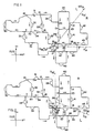
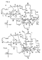
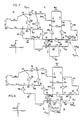
- FIGs. 1-8 the solid lines schematically show a transportation network.
- the transportation network is identical in each of Figs. 1-8.
- the network includes a plurality of stations schematically shown at numerals 30-48, inclusive.
- the stations 30-48 are interconnected by a plurality of path segments indicated by the solid lines extending between a plurality of juncture points indicated by the numerals 10-17 and 20-27.
- the path segments are unidirectional and a vehicle on a path segment may only move in a direction indicated by the arrows adjacent the segments in the figures.
- the path segments are the solid lines extending between juncture points 10-17 and 20-27.
- the plurality of juncture points may be divided into separate groups including a plurality of merge points 20-27 and branch points 10-17.
- a merge point is any juncture point which receives vehicle traffic from two path segments and merges the vehicle traffic into a single path segment exiting the merge point. For example, with reference to merge point 26, traffic enters merge point 26 from either of branch segments extending between juncture points 14 and 26 and juncture points 24 and 26. The vehicle traffic which enters merge point 26 may only exit through the path segment extending between juncture points 15 and 26.
- a branch point is defined as a juncture point where vehicles entering the branch point may arrive from only one path segment but may exit the branch point on any one of two path segments. For example, with reference to branch point 12, it can be seen that vehicle traffic enters branch point 12 only from the path segment between points 12 and 16. Traffic leaving branch point 12 may leave on the path segment extending between point 12 and point 21. Alternatively, traffic may leave branch point 12 on the path segment extending between points 12 and 20.
- station 30 is disposed on the path segment extending between juncture points 11 and 10. Associated with station 30 are two juncture points 30a and 30b. When a vehicle is approaching station 30 on the path segment and if station 30 is its destination station, the vehicle moves off the path segment at juncture point 30a which will conveniently be referred to as a "station-on" point. A vehicle leaving station 30 must pass through juncture point 30b to return to the path segment.
- Station 30b will conveniently be referred to as a "station-off" point.
- Station 46 which is shown enlarged in Fig. 11, also includes a station-on point 46a and a station-off point 46b.
- Figs. 10 and 11 differ in that station 30 of Fig. 10 is a left-handed station in that a vehicle approaching the station must exit to the left at station-on point 30a. To leave station 30 and return to the path segment, a vehicle must approach the path segment from the left at station-off point 30b.
- station 46 is a right-handed station in that a vehicle entering station 46 from the path segment exits to the right at station-on point 46a. A vehicle at station 46 entering the path segment approaches the path from the right at station-off point 46b. It can be seen from the above that station-off points 30b and 46b operate like merge points.
- a plurality of left-handed stations such as station 30 are disposed on the network and includes stations 30, 31, 32, 33, 34, 42, 44, 48.
- the remaining stations are right-handed stations such as station 46.
- a network like that described above can be used in a plurality of transit systems such as personal transit systems as well as material handling systems.
- the network of the present invention is described in reference to a personal rapid transit system having vehicles and guideways described in the aforementioned commonly assigned U.S. patents.
- the pathways will be formed of the guideways disclosed in these references.
- U.S. Pat. No. 4,522,128 (which is incorporated herein by reference)
- a vehicle 10 is shown in a guideway 12.
- the vehicle has wheels 22 which rest on channels 18 to provide verticle support for the vehicle 10.
- a plurality of guide wheels 28 bear against channels 29 to provide lateral support as the vehicle moves on a path segment extending between juncture points.
- the vehicle 10 includes a switch arm 32 which is pivotable between a left switch position and a right switch position.
- the switch arm 32 As a vehicle is approaching a branch point, the switch arm 32 must be switched to the left position if a left turn is desired or to the right position if a right turn is desired. Likewise, this procedure must be followed as the vehicle approaches a station-on point. If the vehicle is approaching a left-handed station and it is desired to enter the station, the switch must be in the left position. If it is not desired to enter the station, the switch must be in the right position.
- the switch Conversely, if the vehicle is approaching a right-handed station and it is desired to enter the station, the switch must be in the right position. If it is not desired to stop at the right-handed station, the switch must be in the left position. Finally, as a vehicle is approaching a merge point, the switch must be in the left position if the vehicle is approaching from the left. The switch must be in the right position if the vehicle is approaching the merge point from the right.
- stations 30, 40, 42 and 46 could represent stations adjacent parking lots in residential neighborhoods.
- Stations 39, 41 and 37 could represent centralized urban areas which include business, government and educational areas.
- the remaining stations could represent any one of a variety of areas such as residential areas and shopping areas. It will be apparent that an individual or a small group of individuals entering a personal vehicle at anyone of stations 30-48 could desire to go to anyone of the remaining stations. Therefore, at any given time there can be a plurality of individual vehicles moving around the path segments heading to a wide variety of destination stations.
- the vehicle As a vehicle moves from a point of origin to a point of destination, it is probable the vehicle will pass through a plurality of juncture points. At each one of these juncture points, the vehicle must be in either a right switch or a left switch orientation.
- the vehicle can be programmed at its point of origin for any given destination point to be instructed to make the proper sequence of left and right switching throughout the network to obtain its destination point through the most efficient path.
- such a scheme either involves the vehicle being provided with on-board programming having the proper sequences of left and right switching for every destination conceivable from every possible point of origin.
- the sequencing scheme can be relayed to an on-board computer from a central computer. However, both of these alternatives are undesirable.
- Neither of these alternatives adequately provides for the possibility to reprogram the vehicle once travel is initiated. Such a need may result due to congestion in a given path segment or due to damage or accident on a path segment.
- the scheme involving the central computer requires transfer from the central computer to the vehicle of a wide variety of information. Namely, the vehicle must be informed of every station along its way and whether or not it is a left-handed station or a right-handed station. Likewise, the vehicle must be informed of all merge points along its path and whether or not the merge point will require a left-handed or right-handed switch. Finally, the vehicle must be informed of every branch point along its path and instructed as to whether or not the vehicle should branch to the left or the right.
- Another problem associated with the above schemes is the method of controlling the vehicle must acknowledge the possibility that the network will change over time. For example, new path segments may be added and old path segments deleted. Also, stations can be added or subtracted from given path segments. Each one of these changes requires substantial reprogramming of either the on-board computer or the central computer. Such programming can become extremely expensive.
- the present invention has been conceived.
- branch points 10-17 it will be appreciated that as a vehicle approaches each of these branch points, a decision is required as to whether the vehicle should be in a left switch mode or a right switch mode. I have determined that this can be accomplished by dividing the plurality of stations into two sets for each branch point. The first set will include those stations which are most efficiently attained by a taking a left turn at the branch point. The second set will include those stations which are most efficiently attained by taking a right turn at the branch point.
- a coordinate system is established for the network.
- a Cartesian coordinate system is superimposed including orthogonal X and Y axes intersecting at a predetermined reference point (0,0). It will be appreciated that while a Cartesian coordinate system is preferred, any other coordinate system, such as radial coordinates, may be employed.
- location defining coordinates (X i ,Y i ) assigned to each of the stations 30-48 a plurality of network dividing lines can be defined for each of the branch points 10-17.
- a network dividing line 10014 shown as a dashed line is provided for branch point 14.
- the network dividing line 10014 includes two line segments with a first line segment having a slope S14' and passing through a point (X14,Y14). The line also includes a second segment which passes through the same point and has a slope S14.
- the network dividing line 10014 is selected to divide the area of the network into two domains indicated by domain R and domain L. The positioning of the line 10014 is selected such that the stations within domain R are most efficiently attainable by taking a right turn at branch point 14. In the case of Fig.
- Figs. 2, 3, 4, 5, 6, 7 and 8 show network dividing lines for branch points 15, 16, 12, 11, 13, 10 and 17, respectively.
- the positioning of the network dividing line for each of the branch points is established by identifying at each of the branch points those stations which are most efficiently attained by taking a right-hand turn at the branch point and those which are most efficiently attained by taking a left-hand turn at the branch point.
- the network dividing line is provided as being a plurality of connected straight line segments separating the two sets of stations into the right-hand domain R of the network and the left-hand domain L of the network for that branch point. Whether a station is considered most efficiently attainable by a right or left turn will depend upon a variety of factors for the particular network such as the length of the path segments and anticipated traffic. With reference to the figures, it can be seen that each of the dividing lines is uniquely defined by the coordinates of the intersection points of its constituent line segments and by the slopes of its end line segments.
- the transmission means will include segmented transmission lines at each of the juncture points which communicates with the vehicle through radio transmitters and receivers located on the vehicle which pass close to the transmission lines as the vehicle moves through the guideway.
- the segmented transmission lines are schematically shown in Fig. 12 as three parallel communication lines 201 which are connected to a wayside computer 202 and transmitter 203 shown in schematic format.
- the on-board equipment is shown within the schematic outline 200 of the vehicle and includes a receiver 204 for receiving information from the wayside line 201 and a transducer 205 for modifying this information in a digital format to be received by a microprocessor schematically identified at 206 which includes logic 207 to process the information to generate identification of the approaching juncture point and switch logic 208 to generate a command to throw a switch to either the right or the left position.
- a destination transducer 209 holds coordinates of the destination station and is readable by the switch logic.
- the command from the switch logic is modified from a transducer 210 to a switch torquer 211 to throw the switch 213.
- a proximity sensor 212 identifies whether or not the switch has been properly thrown and feeds this information via a transducer 215 back to the switch logic.
- the equipment schematically shown in Fig. 12 is known in the art.
- the switch torquer is preferably such as the switch throw mechanism identified by the numeral 50 in U.S. Pat. 4,522,128 to throw the switch shown therein.
- Proximity sensors are old and well-known in the art and commercially available items.
- Equipment for transmitting and receiving information across segmented transmission lines are disclosed in a publicly available paper entitled "Odometer Data Downlink Collision Avoidance System Demonstration Report" produced by the Boeing Company and prepared under contract number DOT-UT-80041 with a release date of August 16, 1982.
- a wayside transmitter transmits to the vehicle information identifying the type of the next approaching juncture point and parameters concerning that juncture point. More specifically, the vehicle is supplied with information identifying the approaching juncture point as being either a merge point, branch point or station-on point.
- the vehicle is instructed as to whether it is a merge point which will require left-hand switching or right-hand switching. If the approaching juncture point is a station-on point, the location defining coordinates of the station will be transmitted to the vehicle as well as information whether the station is a right station or a left station. Finally, if the approaching juncture point is a branch point, the wayside transmitter will transmit to the vehicle the parameters which define the network defining line for that branch point.
- the information received from the wayside transmitter is fed to the on-board microprocessor 206 which uses the information to determine how to throw a switch. For example, if the approaching juncture point is identified as a being a merge point requiring a left switch, the microprocessor 206 determines whether or not the vehicle is in a left switch mode. If not, the switching mechanism is commanded to switch to the left mode. Likewise, if the approaching junction point is identified as being a merge point requiring a right switch, the microprocessor determines whether the switch is in a right mode and, if not, executes a command to effect switching to the right position.
- the on-board microprocessor compares the location defining coordinates of the approaching station to the location defining coordinates of the destination station. If the coordinates are identical, the microprocessor commands the switch to be thrown in either a right or left mode depending on whether the station is a right station or left station, respectively.
- the microprocessor 206 performs an algebraic algorithm to compare the location defining coordinates of the designation station and the coordinates of the intersections of the constituent line segments of the network, dividing line and the slopes of the end segments of the network dividing line. The algorithm determines whether the coordinates lie on the right domain R or left domain L of the branch point. If the coordinates, of the destination station are in the right domain R, the microprocessor executes necessary commands to insure that the switch is thrown to the right. Alternatively, if the coordinates are in the left domain L, the microprocessor executes switch left commands.
- the algorithm may be described by reference to a vehicle having a destination with coordinates (X D ,Y D ) and approaching a branch point having a network dividing line consisting of up to three line segments having intersection points with coordinates (X1,Y1) and (X2,Y2).
- the line segments are shown in Fig. 14.
- the slopes of the line segments are S1, S2 and S3.
- the equations for the three lines are:
- the branch point information transmitted to the vehicle will be the parameters S1, X1 and Y1.
- Y D is compared to Y* so generated and if Y D is greater than Y*, for the particular branch point, this will indicate whether or not Y D is to the left or to the right. Accordingly, the microprocessor determines that the point is in the right or left domain.
- the wayside will transmit the parameters S1, X1, Y1, S2 to the vehicle microprocessor.
- the comparison between Y D and Y* and the remaining logical steps are as above.
- the branch point dividing line has three line segments with slopes S1, S2 and S3, the identifying parameters of S1, X1, Y1, X2, Y2 and S3 are transmitted to the vehicle microprocessor.
- the microprocessor computes S2 and compares X D to X2. If X D is less than X2, the problem is treated identical to that of a network dividing line having two line segments as described above. If X D is greater than or equal to X2, Y* is computed as being equal to S3X D + B3 with the comparison between Y D and Y* being as above.
- An ambiguity can exist depending on whether a vehicle approaches a branch point from the left or the right when viewed in the drawings. For example, a vehicle approaches branch point 16 from the right. In this case, the right domain R is above the network dividing line 10016 (Fig. 3). Conversely, a vehicle approaches branch point 17 from the left. In this case, the right domain R is below the network dividing line 10017 (Fig. 8). Therefore, the vehicle must be transmitted one additional item of binary information as it approaches a branch. point. Namely, having determined whether the destination coordinates (X D ,Y D ) lie above or below the network dividing line, the vehicle must be instructed whether a right or left turn is required.
- a left turn is required for all destination stations where the Y-coordinate Y D of the station is large. (That is, where Y D is greater than a Y-coordinate of a point on the dividing line having an X-coordinate equal to X D ).
- the determination of whether Y D is large is a matter of simple algebra and is readily made by the microprocessor 206 once the line defining parameters are known. Conversely, for a vehicle approaching from the right, a right turn is required for all destination stations where Y D is large.
- Y D is defined as being large where Y D is greater than a Y-coordinate of a point on the dividing line having an X-coordinate equal to X D ). Therefore, the vehicle must be transmitted a binary variable of alternatives Type A or Type B where Type A indicates a right turn is required if Y D is large and Type B indicates a left turn is required if Y D is large.
- branch point 16 is a Type A branch point and branch point 17 is a Type B branch point.
- the logic can accommodate a network dividing line made up of a plurality of line segments. For each additional line segment, an additional intersecting segment coordinate point and an additional slope must be submitted to the vehicle and an additional step must be made in the logic. This is a very small requirement in that each addition of a line segment will result in requiring only a single programming step being added to the logic. Accordingly, the on-board computer can readily handle networks which would include network dividing lines having many line segments.
- the switch logic performed by the microprocessor is shown in Figs. 13a and 13b. If a switch left is required, the microprocessor determines from the proximity sensor 212 whether the switch is thrown left. If it already is in a left position, nothing further need be done. If not, a signal is given to throw the switch to the left and to automatically set the vehicle to slow down after a predetermined time delay. After this command is given, the proximity sensor is analyzed to see if the switch was thrown as required. If it was, the vehicle is given a command to maintain vehicle speed signal which overrides the slow down signal and interrupts the time delay. At this point, no further action is taken until the next juncture point is reached. If the switch was not thrown as required, after the previous described time delay, the vehicle will slow down to a safe speed so the problem can be resolved. Comparative logic is shown for a switch right requirement.
- the method of the present invention will be described with reference to a particular example where a passenger enters a vehicle at station 43 and desires to proceed to station 37.
- the vehicle In the initial position with a vehicle at rest at station 43, the vehicle has already passed a juncture point and received transmitted information regarding the next juncture point. Namely, the vehicle has passed the station-on point for station 43 and received information that the next juncture point is a station-off point which merges from the right of a pathway. Accordingly, the vehicle switch will be in a switch right mode.
- a passenger desiring to travel to station 37 enters the vehicle at station 43 and through any suitable means such as magnetic card, keyboard or otherwise informs the vehicle of the coordinates of the destination station 37 (these coordinates will be referred to as (X37,Y37).
- the vehicle proceeds onto the path segment extending between points 14 and 26.
- the identifying information and parameters for the upcoming junction point 26 are transmitted to the vehicle.
- the vehicle will receive information that the next juncture point is a merge point and requires a switch right mode. Since the vehicle is already in a switch right mode, no further action is taken until after juncture point 26 is passed and identification information and parameters for the next approaching juncture point 15 are received.
- This information identifies juncture point 15 as a Type A branch point with the network dividing line 10015 (as shown in Fig. 2) having the defining parameters of S15', X15, Y15 and S15.
- the on-board microprocessor performs the above described logic to compare these parameters to the destination coordinates X37 and Y37. Determing these coordinates to lie in the left domain L of the network, the microprocessor commands the switching mechanism to switch to a left mode.
- the on-board computer is transmitted information concerning the next approaching juncture point which is a station-on point for station 44.
- the transmitted information includes information identifying the upcoming point as a station-on point which is for a left-handed station and also provide the on-board computer with the coordinates of the station which will be referred to as (X44,Y44).
- the on-board computer compares these coordinates to the destination coordinates (X37,Y37) and notes they are not identical and, accordingly, switches the switch to a right mode to avoid entry onto station 44. Also, at this point, the on-board logic informs the microprocessor that the next approaching juncture point is a station-off point and the right switch mode should be maintained.
- juncture point 25 When passing the station-off point, information concerning the next approaching juncture point 25 is transmitted to the vehicle.
- the transmitted information will indicated that juncture point 25 is a merge point requiring the vehicle to be in a switch left mode. Noting that the vehicle is currently in a switch right mode, a command will be issued switching the vehicle to a switch left mode.
- juncture 25 When juncture 25 is passed, information will be transmitted to the vehicle concerning the next approaching juncture 16.
- the transmitted information will be that juncture 16 is a Type A branch point having a network dividing line 10016 (shown in Fig. 3) with line defining parameters of S16, X16, Y16, X16', Y16' and S16'.
- the on-board microprocesor will perform the above described logic and determine that the coordinates (X37,Y37) of the destination station lie in the right domain R of the network and will command the switch mechanism to assume a switch right mode.
- the vehicle After passing juncture point 16, the vehicle will receive information concerning the next approaching point.
- the information the vehicle will receive is that the next approaching point is a station-on point for a right-handed station having location defining coordinates of X37, Y37.
- the on-board microprocessor will compare these coordinates to the coordinates (X37,Y37) of the destination station and will determine that these coordinates are identical. Informed that the station is a right-hand station, the microprocessor will note that the vehicle is already in a right switch mode and will maintain the vehicle in a right switch mode to enter the station 37 at which point the desired trip will be completed.
- the present invention is particularly suitable to transportation networks where the network structure is subject to change. For example, additional stations and additional path segments may be added. As path segments and stations are added, network dividing lines for any given branch point may change. However, there is no need to change any of the on-board logic for the vehicles. All that is changing are the parameters which will be fed to the vehicle as it passed the preceding juncture point. Reshaping and defining the parameters of the network defining line for any given branch point is a very simple task. For small networks it can be done manually. For very large networks, it would be well within the skill of the art to provide computer programs which will find the most efficient layout for the network dividing lines based on input parameters such as minimizing transportation time between the branch point and the destination station.
- the system is very well suited to handle troublesome problems such as congestion or need for rerouting due to accidents or damage to a path segment.
- a central logic unit will receive information concerning the location of vehicles and their destinations, such a unit can easily determine in advance whether a particular path segment will approach an unreasonably congested state. If a central logic unit so determines that a path segment will, in the future, be at its saturated state, then, as to future passengers, the vehicles can be rerouted away from the potentially troublesome path segment. This is easily done by providing each of the branch points 10-17 with alternate line-defining parameters.
- branch point 16 could be provided with an alternate network dividing line 10016' (shown in Fig. 9) which is established assuming the path segment between juncture points 13 and 23 is no longer available.
- the central computing unit can modify the information at the wayside transmitter at juncture point 25 such that a vehicle passing juncture point 25 will be transmitted line defining parameters S 16a , X 16b , Y 16b , X 16a , Y 16a and S 16a '.
- the central computing unit can replace the substituted information at juncture point 25 with the parameters of line 10016 (shown in Fig. 3).
Landscapes
- Engineering & Computer Science (AREA)
- Mechanical Engineering (AREA)
- Transportation (AREA)
- Health & Medical Sciences (AREA)
- Heart & Thoracic Surgery (AREA)
- Traffic Control Systems (AREA)
- Train Traffic Observation, Control, And Security (AREA)
- Control Of Position, Course, Altitude, Or Attitude Of Moving Bodies (AREA)
- Vehicle Body Suspensions (AREA)
- Control Of Driving Devices And Active Controlling Of Vehicle (AREA)
Claims (12)
- Ein Verfahren zum Steuern der Bewegung eines Fahrzeugs durch ein Netzwerk, das eine Vielzahl von über eine Mehrzahl von Wegsegmenten miteinander verbundene Stationen (30 - 48) und eine Vielzahl von Knotenpunkten (10 - 17; 20 - 27; 30a - 30b) aufweist, die die Wegsegmente miteinander verbinden und eine Mehrzahl von Verzweigungspunkten (10 - 17) aufweisen, das ein Richten eines sich an einen Verzweigungspunkt annähernden Fahrzeugs in eine erste oder eine zweite Richtung erfordert, wobei das Verfahren die folgenden Schritte aufweist:(a) Errichten eines Koordinatensystems für das Netzwerk;(b) Zuordnen von den Ort definierenden Koordinaten (X; Y) zu jeder der Stationen;(c) Identifizieren von eine Linie definierenden Parametern (X, Y; S) für jeden der Verzweigungspunkte, wobei die Parameter eine Teilungslinie durch das Netzwerk definieren, die die Mehrzahl der Stationen in eine erste Gruppe von Stationen, die durch an dem Verzweigungspunkt in eine erste Richtung gerichtete Fahrzeuge erreichbar sind und eine zweite Gruppe von Stationen, die durch ein Fahrzeug, das an dem Verzweigungspunkt in eine zweite Richtung gerichtet wird, erreichbar sind;(d) Zuordnen von den Ort definierenden Koordinaten (X; Y) einer Bestimmungsstation zu einem Fahrzeug;(e) Bewegen des Fahrzeugs entlang eines Wegsegments in Richtung auf einen sich nähernden Verzweigungspunkt (10 - 17);(f) Vergleichen der Koordinaten (X; Y) der Bestimmungsstation zu den die Linie definierenden Parametern (X; Y, S) des sich annähernden Verzweigungspunktes und Bestimmen, ob die Bestimmungsstation ein Element aus einer ersten Gruppe oder aus einer zweiten Gruppe für den sich nähernden Verzweigungspunkt ist; und(g) Richten des Fahrzeugs in eine erste Richtung, wenn die Bestimmungsstation als ein Element aus der ersten Gruppe bestimmt wird und in eine zweite Richtung, wenn die Station als ein Element der zweiten Gruppe bestimmt wird.
- Ein Verfahren nach Anspruch 1, weiter mit:
Identifizieren von alternativen die Linie definierenden Parametern für jeden der Verzweigungspunkte mit den alternativen Parametern, die eine alternative Linie durch das Netzwerk bilden, wobei die Linie die Mehrzahl von Stationen (30 - 48) in einen ersten Satz von Stationen, die von einem an dem Verzweigungspunkt (10 - 17) in eine erste Richtung gerichteten Fahrzeug unter der Annahme, daß ein vorgegebenes Wegsegment für den Fahrzeugverkehr geschlossen ist, erreichbar sind, und in einen zweiten Satz von Stationen, die von einem an dem Verzweigungspunkt in eine zweite Richtung gerichteten Fahrzeug, unter der Annahme, daß das vorgegebene Wegsegment für einen Fahrzeugverkehr geschlossen ist, erreichbar sind. - Verfahren nach Anspruch 2, unter Identifizieren einer Mehrzahl von alternativen eine Linie definierenden Parametern für jeden der Verzweigungspunkte, wobei jeder aus der Mehrzahl von ein Netzwerk teilenden Linien definierenden Parametern davon ausgeht, daß ein anderes Wegsegment für einen Fahrzeugverkehr geschlossen ist.
- Verfahren nach Anspruch 1, wobei die Linie, die die Mehrzahl von Stationen aufteilt, eine gerade Linie ist und die Parameter eine Steigung (S) der Linie und die Koordinaten (X, Y) eines Punktes auf der Linie beinhalten.
- Verfahren nach Anspruch 1, wobei die die Mehrzahl von Stationen aufteilende Linie aus einer Mehrzahl von miteinander verbundenen Liniensegmenten besteht, wobei die Parameter die Koordinaten der Schnittpunkte der Liniensegmente und die Steilheiten der Liniensegmente an den Enden der Teilungslinie aufweist.
- Ein Transportnetzwerk mit:(a) einer Mehrzahl von Stationen (30 - 48);(b) einer Mehrzahl von die Stationen (30 - 48) verbindenden Wegsegmenten;(c) einer Mehrzahl von die Wegsegmente miteinander verbindenden Verzweigungspunkten (10 - 17);(d) einer Mehrzahl von den Ort definierenden, den jeweiligen Stationen zugeordneten Koordinaten (X; Y);(e) einer Mehrzahl von eine Linie definierenden Parametern (X, Y; S) für die Verzweigungspunkte (10 - 17) wobei die Parameter (X, Y; S) eine Teilungslinie durch das Netzwerk definieren und die Mehrzahl von Stationen (30 - 48) in eine erste Gruppe, die von einem Fahrzeug, das an dem Verzweigungspunkt (10 - 17) in eine erste Richtung gerichtet wird, erreichbar sind und eine zweite Gruppe, die durch ein Fahrzeug, das an dem Verzweigungspunkt (10 - 17) in eine zweite Richtung gerichtet wird, erreichbar ist, aufteilt;(f) einem auf dem Netzwerk zur Bewegung entlang der Wegsegmente angeordnetes Fahrzeug;(g) Mitteln zum Zuordnen (209) Von den Ort definierenden Koordinaten einer Bestimmungsstation zu dem Fahrzeug;(h) Mitteln zum Vergleichen (206) der Koordinaten mit den die Linie definierenden Parametern und Bestimmen, ob die Bestimmungsstation ein Element aus einer ersten Gruppe oder aber aus einer zweiten Gruppe ist; und(i) Mitteln (210, 211, 213) zum alternativen Richten des Fahrzeugs in die erste oder in die zweite Richtung.
- Ein Netzwerk nach Anspruch 6, mit:
Mitteln zum Übertragen (202, 203) von die Linie definierenden Parametern eines sich an das Fahrzeug annähernden Verzweigungspunktes. - Ein Netzwerk nach Anspruch 7, wobei die Mehrzahl von Knotenpunkten (10 - 17; 20 - 27; 30a - 30b) eine Mehrzahl von Sammelpunkten (20 - 27) aufweist, wobei ein Fahrzeug an einem Sammelpunkt in eine vorgegebene Richtung gerichtet werden muß;
Mittel zum Übertragen (202, 203) einer den Knotenpunkt als einen Verzweigungspunkt oder einen Sammelpunkt definierender Information zu einem sich an den Knotenpunkt annähernden Fahrzeug. - Ein Netzwerk nach Anspruch 7, wobei die Mehrzahl von Knotenpunkten (10 - 17; 20 - 27; 30a - 30b) eine Mehrzahl von Stationsanfangspunkten (30a) aufweist, die eine Station mit einem Wegsegment verbinden, wobei ein Fahrzeug an einem Stationsanfangspunkt (30a) in eine vorgegebene erforderliche Richtung gerichtet werden muß, um an der Station anzukommen;
Mittel zum Übertragen (202, 203) einer den Knotenpunkt als einen Verzweigungspunkt oder als einen Stationsanfangspunkt definierender Information zu einem sich an den Verzweigungspunkt annähernden Fahrzeug. - In einem Netzwerk mit einer Mehrzahl von Stationen, denen den Ort definierende Koordinaten zugeordnet sind und die die durch eine Mehrzahl von Wegsegmenten miteinander verbunden sind, die eine Mehrzahl von die Segmente miteinander verbindende Knotenpunkte (10 - 17; 20 - 27; 30a - 30b) und eine Mehrzahl von Verzweigungspunkten (10 - 17) aufweisen, wobei die Verzweigungspunkte zugehörige, eine Linie definierende Parameter (X, Y, S) haben, die eine Teilungslinie durch das Netzwerk definieren, die die Mehrzahl von Stationen in eine erste Gruppe von Stationen, welche durch ein Fahrzeug, das in eine erste Richtung gerichtet wird, erreichbar ist, und eine zweite Gruppe von Stationen, die durch ein Fahrzeug, welche durch eine zweite Richtung gerichtet wird, erreichbar sind, aufteilt, wobei das Netzwerk weiter Sende- und Empfangsmittel (202, 203, 204) zum Übertragen von Information zu einem Fahrzeug, Rechenmittel (206, 207), die einem Fahrzeug zum Analysieren der von einem Fahrzeug empfangenen Information zugehörig sind und Mittel zum Richten (210, 211, 213) des Fahrzeugs in eine erste oder in eine zweite Richtung aufweist;
ein Verfahren zum Steuern der Bewegung eines Fahrzeugs zu einer Bestimmungsstation mit:(a) Übermitteln von den Ort definierenden Koordinaten des Bestimmungsorts zu dem Fahrzeug;(b) Bewegen des Fahrzeugs entlang eines Wegsegments in Richtung auf einen sich annähernden Verzweigungspunkt;(c) Übermitteln von die Linie definierenden Parametern einer Teilungslinie, die dem sich annähernden Verzweigungspunkt zugehörig sind, zu dem Fahrzeug;(d) Vergleichen der Koordinaten der Bestimmungsstation mit den die Linie definierenden Parametern und Bestimmen, ob die Bestimmungsstation ein Element einer ersten oder einer zweiten Gruppe für den sich nähernden Verzweigungspunkt ist; und(e) Richten des Fahrzeugs in eine erste Richtung, wenn die Bestimmungsstation als ein Element aus der ersten Gruppe erkannt wird und in eine zweite Richtung, wenn die Station als ein Element aus der zweiten Gruppe erkannt wird. - In dem Netzwerk von Anspruch 10, wobei die Mehrzahl von Knotenpunkten weiter eine Mehrzahl von Sammelpunkten (20 - 27) aufweist, wobei ein Fahrzeug an einem S&mmelpunkt in eine vorgegebene Zwangsrichtung geführt werden muß, wobei das Verfahren weiter die folgenden Schritte aufweist:(a) Bewegen des Fahrzeugs in Richtung auf einen Knotenpunkt (10 - 17; 20 - 27; 30a - 30b);(b) Übermitteln von den Knotenpunkt als einen Verzweigungspunkt (10 - 17) oder einen Sammelpunkt (20 - 27) definierender Information zu dem Fahrzeug;(c) Richten des Fahrzeugs in die vorgegebene Zwangsrichtung, wenn der Knotenpunkt ein Sammelpunkt ist.
- In dem Netzwerk von Anspruch 10, wobei die Mehrzahl von Knotenpunkten weiter eine Mehrzahl von Stationsanfangspunkten aufweist, die eine Station mit einem Wegsegment verbinden, wobei ein Fahrzeug an dem Stationsanfangspunkt in eine vorgegebene Zwangsrichtung geführt werden muß, um die die Station zu erreichen; wobei das Verfahren weiter die folgenden Schritte aufweist:(a) Bewegen des Fahrzeugs in Richtung auf einen Knotenpunkt;(b) Übertragen von den Knotenpunkt als einen Verzweigungspunkt oder einen Stationsanfangspunkt definierender Information zu dem Fahrzeug; und(c) Richten des Fahrzeugs in eine vorgegebene Zwangsrichtung, wenn der Verbindungspunkt ein Stationsanfangspunkt ist.
Priority Applications (1)
| Application Number | Priority Date | Filing Date | Title |
|---|---|---|---|
| AT8787901855T ATE104906T1 (de) | 1986-02-20 | 1987-02-10 | Verfahren und vorrichtung zur regelung eines fahrzeuges. |
Applications Claiming Priority (3)
| Application Number | Priority Date | Filing Date | Title |
|---|---|---|---|
| US832028 | 1986-02-20 | ||
| US06/832,028 US4726299A (en) | 1986-02-20 | 1986-02-20 | Method and apparatus for controlling a vehicle |
| PCT/US1987/000280 WO1987004984A1 (en) | 1986-02-20 | 1987-02-10 | Method and apparatus for controlling a vehicle |
Publications (3)
| Publication Number | Publication Date |
|---|---|
| EP0259443A1 EP0259443A1 (de) | 1988-03-16 |
| EP0259443A4 EP0259443A4 (de) | 1990-02-20 |
| EP0259443B1 true EP0259443B1 (de) | 1994-04-27 |
Family
ID=25260466
Family Applications (1)
| Application Number | Title | Priority Date | Filing Date |
|---|---|---|---|
| EP87901855A Expired - Lifetime EP0259443B1 (de) | 1986-02-20 | 1987-02-10 | Verfahren und vorrichtung zur regelung eines fahrzeuges |
Country Status (7)
| Country | Link |
|---|---|
| US (1) | US4726299A (de) |
| EP (1) | EP0259443B1 (de) |
| JP (1) | JP2592477B2 (de) |
| KR (1) | KR960007039B1 (de) |
| AT (1) | ATE104906T1 (de) |
| DE (1) | DE3789696T2 (de) |
| WO (1) | WO1987004984A1 (de) |
Families Citing this family (29)
| Publication number | Priority date | Publication date | Assignee | Title |
|---|---|---|---|---|
| DE9017742U1 (de) * | 1989-08-24 | 1991-12-19 | Japan Steel Co., Ltd., Tokio/Tokyo | Anlage für den selbsttätigen Transport von an Schienen hängenden Gegenständen |
| JPH0423727A (ja) * | 1990-05-18 | 1992-01-28 | Brother Ind Ltd | 搬送装置 |
| JPH05181527A (ja) * | 1991-12-27 | 1993-07-23 | Mitsubishi Electric Corp | 自動搬送装置 |
| US5511749A (en) | 1994-04-01 | 1996-04-30 | Canac International, Inc. | Remote control system for a locomotive |
| US5595121A (en) * | 1994-04-15 | 1997-01-21 | The Walt Disney Company | Amusement ride and self-propelled vehicle therefor |
| JP3247274B2 (ja) * | 1995-02-28 | 2002-01-15 | 松下電器産業株式会社 | 輸送経路探索装置 |
| US6011508A (en) * | 1997-10-31 | 2000-01-04 | Magnemotion, Inc. | Accurate position-sensing and communications for guideway operated vehicles |
| US6101952A (en) * | 1997-12-24 | 2000-08-15 | Magnemotion, Inc. | Vehicle guidance and switching via magnetic forces |
| US6781524B1 (en) | 2000-03-17 | 2004-08-24 | Magnemotion, Inc. | Passive position-sensing and communications for vehicles on a pathway |
| US6263799B1 (en) * | 2000-05-16 | 2001-07-24 | Herman I. Pardes | Vehicle guideway adaptor for a personal rapid transit system |
| US20030192450A1 (en) * | 2001-03-05 | 2003-10-16 | John Wood | Train management system |
| AU2002347782A1 (en) * | 2001-10-01 | 2003-04-14 | Magnemotion, Inc. | Synchronous machine design and manufacturing |
| US6983701B2 (en) * | 2001-10-01 | 2006-01-10 | Magnemotion, Inc. | Suspending, guiding and propelling vehicles using magnetic forces |
| JP2003146412A (ja) * | 2001-11-12 | 2003-05-21 | Mitsubishi Electric Corp | 搬送システム |
| US20040225421A1 (en) * | 2003-05-05 | 2004-11-11 | Hengning Wu | Personal transportation system |
| NO20032053D0 (no) | 2003-05-07 | 2003-05-07 | Posco Group Ltd | Styreskinne |
| KR20070011577A (ko) | 2004-05-07 | 2007-01-24 | 마그네모션, 인코포레이티드 | 단일 경로를 기반으로 하는 작용기들을 이용한 3차원 동작 |
| KR20070054683A (ko) * | 2004-08-23 | 2007-05-29 | 브룩스 오토메이션 인코퍼레이티드 | 승강기 기반의 도구 적재 및 버퍼링 시스템 |
| KR20080033440A (ko) * | 2005-07-22 | 2008-04-16 | 마그네모션, 인코포레이티드 | 차량의 마그네틱 스위칭에 의해 동작되는 가이드웨이 |
| JP4366663B2 (ja) * | 2007-06-28 | 2009-11-18 | 村田機械株式会社 | 搬送台車システム |
| US9032880B2 (en) | 2009-01-23 | 2015-05-19 | Magnemotion, Inc. | Transport system powered by short block linear synchronous motors and switching mechanism |
| US8616134B2 (en) | 2009-01-23 | 2013-12-31 | Magnemotion, Inc. | Transport system powered by short block linear synchronous motors |
| US8483895B1 (en) | 2009-02-25 | 2013-07-09 | James J. Beregi | Transportation system, system components and process |
| US9802507B2 (en) | 2013-09-21 | 2017-10-31 | Magnemotion, Inc. | Linear motor transport for packaging and other uses |
| CN106541949B (zh) * | 2016-08-09 | 2018-10-09 | 宁波市鄞州乐可机电科技有限公司 | 一种交通设施 |
| CN106541951B (zh) * | 2016-08-11 | 2018-07-10 | 宁波市鄞州乐可机电科技有限公司 | 一种交通设施 |
| CN106553657B (zh) * | 2016-12-06 | 2018-08-17 | 宁波市鄞州乐可机电科技有限公司 | 一种交通设施 |
| US11418965B2 (en) | 2020-05-04 | 2022-08-16 | T-Mobile Usa, Inc. | Hybrid mesh of licensed and unlicensed wireless frequency bands |
| WO2022107419A1 (ja) * | 2020-11-17 | 2022-05-27 | 村田機械株式会社 | 搬送システム |
Family Cites Families (4)
| Publication number | Priority date | Publication date | Assignee | Title |
|---|---|---|---|---|
| US3933099A (en) * | 1971-07-29 | 1976-01-20 | H. Jungheinrich & Co. | Vehicle control apparatus for a closed transporting system |
| BE795267A (fr) * | 1972-02-10 | 1973-05-29 | Secretary Environment Brit | Systemes de transport |
| US3893397A (en) * | 1973-02-28 | 1975-07-08 | Matra Engins | Continuous transport system for trains with programmed vehicles |
| SU620941A1 (ru) * | 1976-12-30 | 1978-08-25 | Предприятие П/Я Р-6543 | Система дл программного управлени монорельсовой дорогой |
-
1986
- 1986-02-20 US US06/832,028 patent/US4726299A/en not_active Expired - Fee Related
-
1987
- 1987-02-10 AT AT8787901855T patent/ATE104906T1/de not_active IP Right Cessation
- 1987-02-10 WO PCT/US1987/000280 patent/WO1987004984A1/en not_active Ceased
- 1987-02-10 KR KR1019870700954A patent/KR960007039B1/ko not_active Expired - Fee Related
- 1987-02-10 DE DE3789696T patent/DE3789696T2/de not_active Expired - Fee Related
- 1987-02-10 JP JP62501457A patent/JP2592477B2/ja not_active Expired - Lifetime
- 1987-02-10 EP EP87901855A patent/EP0259443B1/de not_active Expired - Lifetime
Also Published As
| Publication number | Publication date |
|---|---|
| KR880700750A (ko) | 1988-04-12 |
| JPS63503300A (ja) | 1988-12-02 |
| EP0259443A1 (de) | 1988-03-16 |
| WO1987004984A1 (en) | 1987-08-27 |
| US4726299A (en) | 1988-02-23 |
| ATE104906T1 (de) | 1994-05-15 |
| DE3789696D1 (de) | 1994-06-01 |
| KR960007039B1 (ko) | 1996-05-27 |
| DE3789696T2 (de) | 1994-08-11 |
| JP2592477B2 (ja) | 1997-03-19 |
| EP0259443A4 (de) | 1990-02-20 |
Similar Documents
| Publication | Publication Date | Title |
|---|---|---|
| US4726299A (en) | Method and apparatus for controlling a vehicle | |
| US3895584A (en) | Transportation systems | |
| Varaiya | Smart cars on smart roads: problems of control | |
| US5369591A (en) | Vehicle longitudinal control and collision avoidance system for an automated highway system | |
| JP3653954B2 (ja) | 移動体交通制御システムの移動体装置、移動体交通制御システムの管制局、移動体交通制御システム | |
| CA1166727A (en) | Vehicle collision avoidance system | |
| Varaiya et al. | Sketch of an IVHS systems architecture | |
| Lu et al. | Modeling train movements through complex rail networks | |
| US6026347A (en) | Obstacle avoidance processing method for vehicles using an automated highway system | |
| CA2413080C (en) | Advanced communication-based vehicle control method | |
| US20200098253A1 (en) | Procedure and apparatus for controlling a traffic management system | |
| JP3854071B2 (ja) | 列車群制御システム、列車群制御方法、車上ato装置及び地上制御装置 | |
| AU1542395A (en) | Transport system | |
| CN109459053A (zh) | 一种多目标最优路径自动规划的导航方法 | |
| JPH10100902A (ja) | 走行車両制御方法 | |
| EP4655188A1 (de) | System und verfahren für ein virtuelles annäherungssignal | |
| WO2022096634A1 (en) | Transportation network for multi-featured autonomous vehicles | |
| KR101449740B1 (ko) | 차상중심 열차제어시스템의 주행로 지정, 선로변 장치와 연계하는 방법 | |
| US20250036136A1 (en) | Traffic control system and method | |
| JPH0246428B2 (de) | ||
| JPS6329813A (ja) | 搬送車の合流点進行制御方式 | |
| JPS6318240B2 (de) | ||
| Brader | Computer Control of Automated Transit | |
| JPH087619B2 (ja) | 移動体の走行制御方法 | |
| JP6568830B2 (ja) | 信号保安システム |
Legal Events
| Date | Code | Title | Description |
|---|---|---|---|
| PUAI | Public reference made under article 153(3) epc to a published international application that has entered the european phase |
Free format text: ORIGINAL CODE: 0009012 |
|
| AK | Designated contracting states |
Kind code of ref document: A1 Designated state(s): AT BE CH DE FR GB IT LI LU NL SE |
|
| 17P | Request for examination filed |
Effective date: 19880812 |
|
| A4 | Supplementary search report drawn up and despatched |
Effective date: 19900220 |
|
| 17Q | First examination report despatched |
Effective date: 19921201 |
|
| GRAA | (expected) grant |
Free format text: ORIGINAL CODE: 0009210 |
|
| AK | Designated contracting states |
Kind code of ref document: B1 Designated state(s): AT BE CH DE FR GB IT LI LU NL SE |
|
| REF | Corresponds to: |
Ref document number: 104906 Country of ref document: AT Date of ref document: 19940515 Kind code of ref document: T |
|
| ITF | It: translation for a ep patent filed | ||
| REF | Corresponds to: |
Ref document number: 3789696 Country of ref document: DE Date of ref document: 19940601 |
|
| ET | Fr: translation filed | ||
| EAL | Se: european patent in force in sweden |
Ref document number: 87901855.4 |
|
| PLBE | No opposition filed within time limit |
Free format text: ORIGINAL CODE: 0009261 |
|
| STAA | Information on the status of an ep patent application or granted ep patent |
Free format text: STATUS: NO OPPOSITION FILED WITHIN TIME LIMIT |
|
| 26N | No opposition filed | ||
| PGFP | Annual fee paid to national office [announced via postgrant information from national office to epo] |
Ref country code: FR Payment date: 19990119 Year of fee payment: 13 |
|
| PGFP | Annual fee paid to national office [announced via postgrant information from national office to epo] |
Ref country code: SE Payment date: 19990121 Year of fee payment: 13 Ref country code: GB Payment date: 19990121 Year of fee payment: 13 Ref country code: AT Payment date: 19990121 Year of fee payment: 13 |
|
| PGFP | Annual fee paid to national office [announced via postgrant information from national office to epo] |
Ref country code: DE Payment date: 19990122 Year of fee payment: 13 |
|
| PGFP | Annual fee paid to national office [announced via postgrant information from national office to epo] |
Ref country code: NL Payment date: 19990126 Year of fee payment: 13 |
|
| PGFP | Annual fee paid to national office [announced via postgrant information from national office to epo] |
Ref country code: CH Payment date: 19990129 Year of fee payment: 13 |
|
| PGFP | Annual fee paid to national office [announced via postgrant information from national office to epo] |
Ref country code: BE Payment date: 19990208 Year of fee payment: 13 |
|
| PGFP | Annual fee paid to national office [announced via postgrant information from national office to epo] |
Ref country code: LU Payment date: 19990310 Year of fee payment: 13 |
|
| PG25 | Lapsed in a contracting state [announced via postgrant information from national office to epo] |
Ref country code: LU Free format text: LAPSE BECAUSE OF NON-PAYMENT OF DUE FEES Effective date: 20000210 Ref country code: GB Free format text: LAPSE BECAUSE OF NON-PAYMENT OF DUE FEES Effective date: 20000210 Ref country code: AT Free format text: LAPSE BECAUSE OF NON-PAYMENT OF DUE FEES Effective date: 20000210 |
|
| PG25 | Lapsed in a contracting state [announced via postgrant information from national office to epo] |
Ref country code: SE Free format text: LAPSE BECAUSE OF NON-PAYMENT OF DUE FEES Effective date: 20000211 |
|
| PG25 | Lapsed in a contracting state [announced via postgrant information from national office to epo] |
Ref country code: BE Free format text: LAPSE BECAUSE OF NON-PAYMENT OF DUE FEES Effective date: 20000228 |
|
| PG25 | Lapsed in a contracting state [announced via postgrant information from national office to epo] |
Ref country code: LI Free format text: LAPSE BECAUSE OF NON-PAYMENT OF DUE FEES Effective date: 20000229 Ref country code: CH Free format text: LAPSE BECAUSE OF NON-PAYMENT OF DUE FEES Effective date: 20000229 |
|
| BERE | Be: lapsed |
Owner name: THE REGENTS OF THE UNIVERSITY OF MINNESOTA Effective date: 20000228 |
|
| PG25 | Lapsed in a contracting state [announced via postgrant information from national office to epo] |
Ref country code: NL Free format text: LAPSE BECAUSE OF NON-PAYMENT OF DUE FEES Effective date: 20000901 |
|
| GBPC | Gb: european patent ceased through non-payment of renewal fee |
Effective date: 20000210 |
|
| EUG | Se: european patent has lapsed |
Ref document number: 87901855.4 |
|
| REG | Reference to a national code |
Ref country code: CH Ref legal event code: PL |
|
| PG25 | Lapsed in a contracting state [announced via postgrant information from national office to epo] |
Ref country code: FR Free format text: LAPSE BECAUSE OF NON-PAYMENT OF DUE FEES Effective date: 20001031 |
|
| NLV4 | Nl: lapsed or anulled due to non-payment of the annual fee |
Effective date: 20000901 |
|
| PG25 | Lapsed in a contracting state [announced via postgrant information from national office to epo] |
Ref country code: DE Free format text: LAPSE BECAUSE OF NON-PAYMENT OF DUE FEES Effective date: 20001201 |
|
| REG | Reference to a national code |
Ref country code: FR Ref legal event code: ST |
|
| PG25 | Lapsed in a contracting state [announced via postgrant information from national office to epo] |
Ref country code: IT Free format text: LAPSE BECAUSE OF NON-PAYMENT OF DUE FEES;WARNING: LAPSES OF ITALIAN PATENTS WITH EFFECTIVE DATE BEFORE 2007 MAY HAVE OCCURRED AT ANY TIME BEFORE 2007. THE CORRECT EFFECTIVE DATE MAY BE DIFFERENT FROM THE ONE RECORDED. Effective date: 20050210 |