EP0257719A1 - Appareil pour chauffer de la vapeur produite par de l'eau de refroidissement - Google Patents
Appareil pour chauffer de la vapeur produite par de l'eau de refroidissement Download PDFInfo
- Publication number
- EP0257719A1 EP0257719A1 EP87201611A EP87201611A EP0257719A1 EP 0257719 A1 EP0257719 A1 EP 0257719A1 EP 87201611 A EP87201611 A EP 87201611A EP 87201611 A EP87201611 A EP 87201611A EP 0257719 A1 EP0257719 A1 EP 0257719A1
- Authority
- EP
- European Patent Office
- Prior art keywords
- gas
- steam
- cooled
- guiding means
- tube
- Prior art date
- Legal status (The legal status is an assumption and is not a legal conclusion. Google has not performed a legal analysis and makes no representation as to the accuracy of the status listed.)
- Granted
Links
- 239000000498 cooling water Substances 0.000 title claims abstract description 13
- 238000010438 heat treatment Methods 0.000 title claims description 9
- 238000000034 method Methods 0.000 claims abstract description 16
- XLYOFNOQVPJJNP-UHFFFAOYSA-N water Substances O XLYOFNOQVPJJNP-UHFFFAOYSA-N 0.000 claims description 7
- 239000000203 mixture Substances 0.000 claims description 2
- 239000007789 gas Substances 0.000 abstract description 40
- 239000002918 waste heat Substances 0.000 abstract 1
- 238000009434 installation Methods 0.000 description 5
- 238000001816 cooling Methods 0.000 description 4
- 239000002826 coolant Substances 0.000 description 3
- 239000002245 particle Substances 0.000 description 3
- 229920006395 saturated elastomer Polymers 0.000 description 3
- 239000004071 soot Substances 0.000 description 3
- 239000012530 fluid Substances 0.000 description 2
- 238000012986 modification Methods 0.000 description 2
- 230000004048 modification Effects 0.000 description 2
- 230000015572 biosynthetic process Effects 0.000 description 1
- 238000009833 condensation Methods 0.000 description 1
- 230000005494 condensation Effects 0.000 description 1
- 239000000463 material Substances 0.000 description 1
- 238000003786 synthesis reaction Methods 0.000 description 1
Images


Classifications
-
- F—MECHANICAL ENGINEERING; LIGHTING; HEATING; WEAPONS; BLASTING
- F22—STEAM GENERATION
- F22B—METHODS OF STEAM GENERATION; STEAM BOILERS
- F22B1/00—Methods of steam generation characterised by form of heating method
- F22B1/02—Methods of steam generation characterised by form of heating method by exploitation of the heat content of hot heat carriers
- F22B1/18—Methods of steam generation characterised by form of heating method by exploitation of the heat content of hot heat carriers the heat carrier being a hot gas, e.g. waste gas such as exhaust gas of internal-combustion engines
- F22B1/1838—Methods of steam generation characterised by form of heating method by exploitation of the heat content of hot heat carriers the heat carrier being a hot gas, e.g. waste gas such as exhaust gas of internal-combustion engines the hot gas being under a high pressure, e.g. in chemical installations
- F22B1/1846—Methods of steam generation characterised by form of heating method by exploitation of the heat content of hot heat carriers the heat carrier being a hot gas, e.g. waste gas such as exhaust gas of internal-combustion engines the hot gas being under a high pressure, e.g. in chemical installations the hot gas being loaded with particles, e.g. waste heat boilers after a coal gasification plant
-
- F—MECHANICAL ENGINEERING; LIGHTING; HEATING; WEAPONS; BLASTING
- F22—STEAM GENERATION
- F22B—METHODS OF STEAM GENERATION; STEAM BOILERS
- F22B1/00—Methods of steam generation characterised by form of heating method
- F22B1/02—Methods of steam generation characterised by form of heating method by exploitation of the heat content of hot heat carriers
- F22B1/18—Methods of steam generation characterised by form of heating method by exploitation of the heat content of hot heat carriers the heat carrier being a hot gas, e.g. waste gas such as exhaust gas of internal-combustion engines
- F22B1/1884—Hot gas heating tube boilers with one or more heating tubes
Definitions
- the invention relates to a process and an apparatus for heating steam formed from cooling water in a heat exchanger for hot gas.
- a heat exchanger for example in the form of a spiral tube, through which the gas to be cooled is passed.
- the process gas in question has a temperature of above 1300 °C and a gas pressure of more than 30 bar.
- the heat exchanger is cooled by a coolant, for example water, said coolant usually being above the gas pressure. Due to the high heat load and the relatively long residence time to and of the coolant respectively, steam is formed which is caught in a compartment provided for that purpose. This steam is saturated.
- the steam should be brought into an unsaturated state, since saturated steam is often difficult to handle on account of condensation.
- the steam is brought into an unsaturated state by heating it further. To this end, the steam is passed out of a compartment to the outside and led to a separate superheater. In the superheater the steam is heated by the provision of heat.
- This process has the disadvantage that extra energy is required for heating the steam in the superheater. Moreover, the installation is relatively voluminous in view of the fact that the superheater is located outside the actual heat exchanger and connected to it by means of pipes.
- the present invention therefore provides a process for heating steam formed from cooling water in a heat exchanger for hot gas, characterized in that the steam is heated by the gas to be cooled.
- the invention also provides an apparatus for carrying out the above process comprising a vessel with an inlet for the gas to be cooled, a compartment for cooling water with a pipe or tube system for transmitting the gas to be cooled and a collecting space for generated steam, characterized by one or more superheater modules or guiding means connected to the said tube system with an outlet for the discharge of the cooled gas and a steam tube connected to the collecting space and passing through the superheater module(s) or guiding means.
- the heat in the process gas is used to obtain superheated steam without the use of separate superheaters located outside the cooling installation.
- the steam is heated by gas that has already cooled off somewhat.
- Direct heating of the steam by the still uncooled gases would, in view of the high temperature of the gas (1300 °C), give rise to material problems.
- the cooled gas is led through a space for heating the steam in which the pressure is determined by the steam to be heated.
- costly measures were necessary to cope with the high gas pressures.
- the velocity of the gas being cooled is kept above a certain minimum. This considerably reduces the chance of dirt particles settling out.
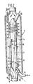
- the apparatus of the invention comprises a vessel 1, provided with a supply connection 2 for the gas to be cooled, a compartment 3 for cooling water, a tube system 4, which serves as a heat exchanger, for transmitting the gas to be cooled, and a collecting space 5 for collecting steam formed from the cooling water.
- the tube system 4 may for example consist of a spiral tube.
- the tube system 4 serving as heat exchanger is connected at least one superheater module or guiding means 7, which is provided with an outlet 6 for the cooled gas, as well as a steam tube 8, which can, for example, be in the form of a spiral, the steam tube 8 being connected to the collecting space 5 and passing through the superheater module or guiding means 7.
- the tube system 4 serving as heat exchanger is connected to the superheater module or guiding means 7 near the steam tube 8 in any way suitable for the purpose.
- the cross section of the guiding means 7 is advantageously considerably larger than that of the tube system 4.
- the steam leaving the steam tube 8 can be mixed with the saturated steam from the collecting space 5 which is fed through the bypass-pipe 10. This makes it possible to maintain the temperature of the superheated steam from the pipe 11 as constant as possible, while also controlling the gas temperature from the pipe 6 in a limited manner.
- the valve 9 is connected via a control pipe 12 to the temperature sensor 13.
- FIG. 1b an advantageous embodiment of the invention is represented.
- the same reference numerals as in fig. 1a have been used.
- An arrangement of two superheater modules 7 and a central down comer 100 are shown.
- only one superheater module 7 is shown as being connected to the respective inlets and outlets for steam and gas, but it should be clear that the other superheater module(s) 7 is (are) also provided with respective inlets and outlets for steam and gas.
- the steam by-pass 10 is arranged inside the vessel 1 and the valve 9 has not been represented.
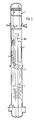
- Fig. 2 shows the superheater module or guiding means 7, of fig 1a on a larger scale.
- the steam tube 8 can consist of a double spiral tube. It will be appreciated that any suitable number of such tubes can be applied.
- the gas flows into the superheater module or guiding means 7 at the top and has by then already been cooled somewhat.
- the steam to be heated flows through the steam tube co-currently with the gas, although it is also possible for the two media to flow in counter-current.
- hybrid lay-out options can be applied.
- the term hybrid lay-out option means that, e.g. a superheater module may comprise a first co-current portion in which the gas is introduced and a second counter-current portion.
- a pipe 14 is fitted in the guiding means 7.
- the pipe 14 serves the function of supply pipe for cooling water or water/steam mixture, for which purpose the pipe 14 is provided with a water supply connection 15 and a cooling water/steam discharge connection 16.
- the pipe 14 serves to reduce the cross section of the guiding means 7 in order to keep the flow velocity of the gas above a minimum value so as to make the chance of ash and soot particles being deposited in the guiding means 7 as small as possible.
- a pipe 17 is fitted within the pipe 14 and connected via passages, e.g. 18, 19, to openings in the pipe 14.
- the pipe 17 is provided with a fluid supply line 20.
- This arrangement enables a suitable fluid, such as steam or compressed gas or synthesis gas, to be blown into the superheater module or guiding means 7 via the connection 20, the pipe 17 and the passages 18 and 19 and thereby remove any deposit of ash or soot.
- a suitable fluid such as steam or compressed gas or synthesis gas
- each superheater module 7 is connected to at least two pipes or tubes for transmitting the gas to be cooled.
- each superheater module 7 has been shown as being connected in such a manner, but it should be clear that the other superheater module(s) 7 is (are) also connected in such a manner.
- the installation operates as follows.
- the gas to be cooled is passed via the connection 2, the tube system 4 and the superheater module or guiding means 7 through the vessel 1 and discharged via the outlet 6 to the outside.
- the gas is successively cooled by the cooling water, while cooling off further in the guiding means 7, but in doing so also heating up the steam formed from the cooling water and caught in the collecting space 5 and fed through the steam tube 8.
- the heated steam reaches such a temperature that it is passed to the outside via steam tube 8 in an unsaturated state.
- any suitable number of gas transmitting tubes may enter a superheater module.
- the central down-comer tube should be extended with the gastubes entering the superheater module circumferentially at a certain pitch.
Applications Claiming Priority (2)
| Application Number | Priority Date | Filing Date | Title |
|---|---|---|---|
| NL8602162 | 1986-08-26 | ||
| NL8602162 | 1986-08-26 |
Publications (2)
| Publication Number | Publication Date |
|---|---|
| EP0257719A1 true EP0257719A1 (fr) | 1988-03-02 |
| EP0257719B1 EP0257719B1 (fr) | 1991-07-03 |
Family
ID=19848452
Family Applications (1)
| Application Number | Title | Priority Date | Filing Date |
|---|---|---|---|
| EP87201611A Expired - Lifetime EP0257719B1 (fr) | 1986-08-26 | 1987-08-26 | Appareil pour chauffer de la vapeur produite par de l'eau de refroidissement |
Country Status (16)
| Country | Link |
|---|---|
| US (1) | US4796570A (fr) |
| EP (1) | EP0257719B1 (fr) |
| JP (1) | JP2523336B2 (fr) |
| CN (1) | CN1012753B (fr) |
| AU (1) | AU593932B2 (fr) |
| BR (1) | BR8704337A (fr) |
| CA (1) | CA1309907C (fr) |
| CS (1) | CS273331B2 (fr) |
| DD (1) | DD262063A5 (fr) |
| DE (1) | DE3771147D1 (fr) |
| ES (1) | ES2022876B3 (fr) |
| IN (1) | IN170062B (fr) |
| NO (1) | NO166300C (fr) |
| PT (1) | PT85577B (fr) |
| SU (1) | SU1658828A3 (fr) |
| ZA (1) | ZA876257B (fr) |
Cited By (5)
| Publication number | Priority date | Publication date | Assignee | Title |
|---|---|---|---|---|
| WO2002093073A2 (fr) * | 2001-05-17 | 2002-11-21 | Shell Internationale Research Maatschappij B.V. | Appareil de chauffage de vapeur |
| WO2003036165A2 (fr) | 2001-10-22 | 2003-05-01 | Shell Internationale Research Maatschappij B.V. | Procede de reduction de la temperature d'un gaz contenant de l'hydrogene et du monoxyde de carbone et echangeur thermique mis en oeuvre dans ledit procede |
| EP1059486A3 (fr) * | 1999-06-10 | 2003-05-02 | Borsig GmbH | Procédé et générateur de vapeur pour récupérer la chaleur d'un gaz chaud de processus |
| US6840199B2 (en) | 2000-05-19 | 2005-01-11 | Shell Oil Company | Process for heating system |
| US7628121B2 (en) | 2006-04-12 | 2009-12-08 | Shell Oil Company | Apparatus and process for cooling hot gas |
Families Citing this family (8)
| Publication number | Priority date | Publication date | Assignee | Title |
|---|---|---|---|---|
| CN1272607A (zh) * | 2000-05-22 | 2000-11-08 | 郑业琦 | 持续水雾化加热产生高压饱和蒸汽装置及其产生方法 |
| CN2424370Y (zh) * | 2000-05-25 | 2001-03-21 | 郑业琦 | 持续水雾化加热产生高压饱和蒸汽装置 |
| CN1123729C (zh) * | 2001-02-23 | 2003-10-08 | 郑业琦 | 产生高压饱和蒸汽的装置 |
| US20100282450A1 (en) * | 2007-05-31 | 2010-11-11 | Dominicus Fredericus Mulder | Heat exchanger shell assembly and method of assembling |
| CN101539287B (zh) * | 2009-05-06 | 2011-01-05 | 清华大学 | 一种蒸汽发生器 |
| WO2017058041A1 (fr) * | 2015-09-28 | 2017-04-06 | Михаил Александрович НАДТОЧЕЙ | Procédé de fonctionnement de chaudière, et chaudière pour sa mise en œuvre (variantes) |
| CN112097229B (zh) * | 2019-11-19 | 2022-08-02 | 中船重工(上海)新能源有限公司 | 一种蒸汽发生器 |
| AT525551B1 (de) * | 2022-05-16 | 2023-05-15 | Hydrotaurus C Tech Gmbh | Wärmekraftmaschine |
Citations (5)
| Publication number | Priority date | Publication date | Assignee | Title |
|---|---|---|---|---|
| US2820437A (en) * | 1952-11-24 | 1958-01-21 | Ilune Georges | Heat-exchange evaporator apparatus |
| FR1428131A (fr) * | 1964-02-19 | 1966-02-11 | Reactor Centrum Nederland | échangeur de chaleur composite et installation de réacteur équipée d'un échangeur de chaleur de ce type |
| DE1959228A1 (de) * | 1969-11-26 | 1971-06-09 | Lentjes Dampfkessel Ferd | Verfahren zum Betrieb eines Dampfkessels |
| US4488513A (en) * | 1983-08-29 | 1984-12-18 | Texaco Development Corp. | Gas cooler for production of superheated steam |
| CH652474A5 (en) * | 1982-12-06 | 1985-11-15 | Sulzer Ag | Flow-medium-heated steam generator |
Family Cites Families (5)
| Publication number | Priority date | Publication date | Assignee | Title |
|---|---|---|---|---|
| DE3121297C2 (de) * | 1981-05-29 | 1984-05-17 | M.A.N. Maschinenfabrik Augsburg-Nürnberg AG, 4200 Oberhausen | Vorrichtung zum Regeln der Temperatur eines korrosiven Gases, insbesondere Synthesegas |
| US4462339A (en) * | 1983-08-29 | 1984-07-31 | Texaco Development Corporation | Gas cooler for production of saturated or superheated steam, or both |
| JPS6138303A (ja) * | 1984-07-31 | 1986-02-24 | 川崎重工業株式会社 | 転炉排ガス処理装置の過熱蒸気発生装置 |
| DE3447265A1 (de) * | 1984-12-22 | 1986-06-26 | L. & C. Steinmüller GmbH, 5270 Gummersbach | Verfahren und vorrichtung zur erzeugung von hochgespanntem und ueberhitztem dampf |
| JPH0788925B2 (ja) * | 1986-01-20 | 1995-09-27 | 大阪瓦斯株式会社 | ボイラ |
-
1987
- 1987-08-05 IN IN565/MAS/87A patent/IN170062B/en unknown
- 1987-08-05 CA CA000543671A patent/CA1309907C/fr not_active Expired - Fee Related
- 1987-08-24 SU SU874203142A patent/SU1658828A3/ru active
- 1987-08-24 AU AU77351/87A patent/AU593932B2/en not_active Ceased
- 1987-08-24 DD DD87306293A patent/DD262063A5/de not_active IP Right Cessation
- 1987-08-24 BR BR8704337A patent/BR8704337A/pt not_active IP Right Cessation
- 1987-08-24 ZA ZA876257A patent/ZA876257B/xx unknown
- 1987-08-24 NO NO873563A patent/NO166300C/no unknown
- 1987-08-24 CS CS620087A patent/CS273331B2/cs not_active IP Right Cessation
- 1987-08-24 JP JP62208400A patent/JP2523336B2/ja not_active Expired - Fee Related
- 1987-08-24 CN CN87105782A patent/CN1012753B/zh not_active Expired
- 1987-08-24 PT PT85577A patent/PT85577B/pt not_active IP Right Cessation
- 1987-08-26 EP EP87201611A patent/EP0257719B1/fr not_active Expired - Lifetime
- 1987-08-26 ES ES87201611T patent/ES2022876B3/es not_active Expired - Lifetime
- 1987-08-26 DE DE8787201611T patent/DE3771147D1/de not_active Expired - Fee Related
- 1987-09-30 US US07/079,534 patent/US4796570A/en not_active Expired - Lifetime
Patent Citations (5)
| Publication number | Priority date | Publication date | Assignee | Title |
|---|---|---|---|---|
| US2820437A (en) * | 1952-11-24 | 1958-01-21 | Ilune Georges | Heat-exchange evaporator apparatus |
| FR1428131A (fr) * | 1964-02-19 | 1966-02-11 | Reactor Centrum Nederland | échangeur de chaleur composite et installation de réacteur équipée d'un échangeur de chaleur de ce type |
| DE1959228A1 (de) * | 1969-11-26 | 1971-06-09 | Lentjes Dampfkessel Ferd | Verfahren zum Betrieb eines Dampfkessels |
| CH652474A5 (en) * | 1982-12-06 | 1985-11-15 | Sulzer Ag | Flow-medium-heated steam generator |
| US4488513A (en) * | 1983-08-29 | 1984-12-18 | Texaco Development Corp. | Gas cooler for production of superheated steam |
Cited By (11)
| Publication number | Priority date | Publication date | Assignee | Title |
|---|---|---|---|---|
| EP1059486A3 (fr) * | 1999-06-10 | 2003-05-02 | Borsig GmbH | Procédé et générateur de vapeur pour récupérer la chaleur d'un gaz chaud de processus |
| US6840199B2 (en) | 2000-05-19 | 2005-01-11 | Shell Oil Company | Process for heating system |
| WO2002093073A2 (fr) * | 2001-05-17 | 2002-11-21 | Shell Internationale Research Maatschappij B.V. | Appareil de chauffage de vapeur |
| WO2002093073A3 (fr) * | 2001-05-17 | 2003-02-13 | Shell Int Research | Appareil de chauffage de vapeur |
| US6886501B2 (en) | 2001-05-17 | 2005-05-03 | Shell Oil Company | Apparatus and process for heating steam |
| KR100864383B1 (ko) * | 2001-05-17 | 2008-10-20 | 쉘 인터내셔날 리서치 마챠피즈 비.브이. | 증기 가열 장치 및 방법 |
| WO2003036165A2 (fr) | 2001-10-22 | 2003-05-01 | Shell Internationale Research Maatschappij B.V. | Procede de reduction de la temperature d'un gaz contenant de l'hydrogene et du monoxyde de carbone et echangeur thermique mis en oeuvre dans ledit procede |
| WO2003036165A3 (fr) * | 2001-10-22 | 2003-10-23 | Shell Int Research | Procede de reduction de la temperature d'un gaz contenant de l'hydrogene et du monoxyde de carbone et echangeur thermique mis en oeuvre dans ledit procede |
| AU2002350595B2 (en) * | 2001-10-22 | 2008-01-31 | Shell Internationale Research Maatschappij B.V. | Process to reduce the temperature of a hydrogen and carbon monoxide containing gas and heat exchanger for use in said process |
| US7597067B2 (en) | 2001-10-22 | 2009-10-06 | Shell Oil Company | Process to reduce the temperature of a hydrogen and carbon monoxide containing gas and heat exchanger for use in said process |
| US7628121B2 (en) | 2006-04-12 | 2009-12-08 | Shell Oil Company | Apparatus and process for cooling hot gas |
Also Published As
| Publication number | Publication date |
|---|---|
| IN170062B (fr) | 1992-02-01 |
| NO166300B (no) | 1991-03-18 |
| NO166300C (no) | 1991-06-26 |
| NO873563D0 (no) | 1987-08-24 |
| DD262063A5 (de) | 1988-11-16 |
| US4796570A (en) | 1989-01-10 |
| AU7735187A (en) | 1988-03-03 |
| JP2523336B2 (ja) | 1996-08-07 |
| ZA876257B (en) | 1988-03-01 |
| ES2022876B3 (es) | 1991-12-16 |
| EP0257719B1 (fr) | 1991-07-03 |
| DE3771147D1 (de) | 1991-08-08 |
| AU593932B2 (en) | 1990-02-22 |
| PT85577A (pt) | 1988-08-17 |
| CN1012753B (zh) | 1991-06-05 |
| PT85577B (pt) | 1993-07-30 |
| CN87105782A (zh) | 1988-03-09 |
| BR8704337A (pt) | 1988-04-19 |
| CS273331B2 (en) | 1991-03-12 |
| JPS6361805A (ja) | 1988-03-18 |
| CS620087A2 (en) | 1990-07-12 |
| CA1309907C (fr) | 1992-11-10 |
| SU1658828A3 (ru) | 1991-06-23 |
| NO873563L (no) | 1988-02-29 |
Similar Documents
| Publication | Publication Date | Title |
|---|---|---|
| US4796570A (en) | Apparatus for heating steam formed from cooling water | |
| US4566406A (en) | Sludge removing apparatus for a steam generator | |
| EP0013580B1 (fr) | Méthode pour refroidir un courant de gaz et un échangeur de chaleur générateur de vapeur utilisant cette méthode | |
| US4493291A (en) | Gas cooler arrangement | |
| US4309196A (en) | Coal gasification apparatus | |
| US4352341A (en) | Waste heat boiler and steam superheater system | |
| US3771497A (en) | Vapor generator control | |
| US4148281A (en) | Steam generator and pressurized-water nuclear reactors | |
| KR100976436B1 (ko) | 클라우스 플랜트용 폐열 보일러 | |
| US5566750A (en) | Method and apparatus for cooling hot gases | |
| US4421065A (en) | Heating equipment for an installation using steam and heated gas | |
| CA1142911A (fr) | Echangeur de chaleur generateur de vapeur | |
| US4267882A (en) | Heat exchanger for cooling a high pressure gas | |
| JPS5950884B2 (ja) | 蒸気発生装置にガス抜きされた供給水を供給する方法及び装置 | |
| GB2100408A (en) | Method of and apparatus for regulating the temperature of heat exchanger supply gas | |
| US4131085A (en) | Vapor generating unit blowdown arrangement | |
| US4243097A (en) | Waste heat boiler | |
| DE3042142A1 (de) | Wirbelbett-gaserzeuger | |
| GB2155821A (en) | Gas cleaning apparatus | |
| CN105408686A (zh) | 用于从热工艺流回收热的壳管式装置 | |
| GB1597509A (en) | Heat exchanger for use in a high temperature reactor | |
| AU783495B2 (en) | Steam generator | |
| US2781029A (en) | Feed water heater | |
| RU2031345C1 (ru) | Подогреватель типа труба в трубе | |
| US4414923A (en) | Heat recovery boiler for high pressure gas |
Legal Events
| Date | Code | Title | Description |
|---|---|---|---|
| PUAI | Public reference made under article 153(3) epc to a published international application that has entered the european phase |
Free format text: ORIGINAL CODE: 0009012 |
|
| AK | Designated contracting states |
Kind code of ref document: A1 Designated state(s): BE DE ES FR GB IT NL SE |
|
| 17P | Request for examination filed |
Effective date: 19880704 |
|
| 17Q | First examination report despatched |
Effective date: 19900213 |
|
| GRAA | (expected) grant |
Free format text: ORIGINAL CODE: 0009210 |
|
| AK | Designated contracting states |
Kind code of ref document: B1 Designated state(s): BE DE ES FR GB IT NL SE |
|
| REF | Corresponds to: |
Ref document number: 3771147 Country of ref document: DE Date of ref document: 19910808 |
|
| ITF | It: translation for a ep patent filed |
Owner name: JACOBACCI & PERANI S.P.A. |
|
| ET | Fr: translation filed | ||
| PLBE | No opposition filed within time limit |
Free format text: ORIGINAL CODE: 0009261 |
|
| STAA | Information on the status of an ep patent application or granted ep patent |
Free format text: STATUS: NO OPPOSITION FILED WITHIN TIME LIMIT |
|
| 26N | No opposition filed | ||
| EAL | Se: european patent in force in sweden |
Ref document number: 87201611.8 |
|
| REG | Reference to a national code |
Ref country code: GB Ref legal event code: IF02 |
|
| PGFP | Annual fee paid to national office [announced via postgrant information from national office to epo] |
Ref country code: FR Payment date: 20050621 Year of fee payment: 19 |
|
| PGFP | Annual fee paid to national office [announced via postgrant information from national office to epo] |
Ref country code: SE Payment date: 20050711 Year of fee payment: 19 |
|
| PGFP | Annual fee paid to national office [announced via postgrant information from national office to epo] |
Ref country code: GB Payment date: 20050728 Year of fee payment: 19 |
|
| PGFP | Annual fee paid to national office [announced via postgrant information from national office to epo] |
Ref country code: NL Payment date: 20050808 Year of fee payment: 19 |
|
| PGFP | Annual fee paid to national office [announced via postgrant information from national office to epo] |
Ref country code: BE Payment date: 20050816 Year of fee payment: 19 Ref country code: ES Payment date: 20050816 Year of fee payment: 19 |
|
| PGFP | Annual fee paid to national office [announced via postgrant information from national office to epo] |
Ref country code: DE Payment date: 20050825 Year of fee payment: 19 |
|
| PG25 | Lapsed in a contracting state [announced via postgrant information from national office to epo] |
Ref country code: SE Free format text: LAPSE BECAUSE OF NON-PAYMENT OF DUE FEES Effective date: 20060827 |
|
| PG25 | Lapsed in a contracting state [announced via postgrant information from national office to epo] |
Ref country code: BE Free format text: LAPSE BECAUSE OF NON-PAYMENT OF DUE FEES Effective date: 20060831 |
|
| PGFP | Annual fee paid to national office [announced via postgrant information from national office to epo] |
Ref country code: IT Payment date: 20060831 Year of fee payment: 20 |
|
| PG25 | Lapsed in a contracting state [announced via postgrant information from national office to epo] |
Ref country code: DE Free format text: LAPSE BECAUSE OF NON-PAYMENT OF DUE FEES Effective date: 20070301 Ref country code: NL Free format text: LAPSE BECAUSE OF NON-PAYMENT OF DUE FEES Effective date: 20070301 |
|
| EUG | Se: european patent has lapsed | ||
| GBPC | Gb: european patent ceased through non-payment of renewal fee |
Effective date: 20060826 |
|
| NLV4 | Nl: lapsed or anulled due to non-payment of the annual fee |
Effective date: 20070301 |
|
| REG | Reference to a national code |
Ref country code: FR Ref legal event code: ST Effective date: 20070430 |
|
| REG | Reference to a national code |
Ref country code: ES Ref legal event code: FD2A Effective date: 20060828 |
|
| PG25 | Lapsed in a contracting state [announced via postgrant information from national office to epo] |
Ref country code: GB Free format text: LAPSE BECAUSE OF NON-PAYMENT OF DUE FEES Effective date: 20060826 |
|
| BERE | Be: lapsed |
Owner name: *SHELL INTERNATIONALE RESEARCH MAATSCHAPPIJ B.V. Effective date: 20060831 |
|
| PG25 | Lapsed in a contracting state [announced via postgrant information from national office to epo] |
Ref country code: ES Free format text: LAPSE BECAUSE OF NON-PAYMENT OF DUE FEES Effective date: 20060828 |
|
| PG25 | Lapsed in a contracting state [announced via postgrant information from national office to epo] |
Ref country code: FR Free format text: LAPSE BECAUSE OF NON-PAYMENT OF DUE FEES Effective date: 20060831 |