EP0257547A2 - Roller shutter box - Google Patents
Roller shutter box Download PDFInfo
- Publication number
- EP0257547A2 EP0257547A2 EP87112043A EP87112043A EP0257547A2 EP 0257547 A2 EP0257547 A2 EP 0257547A2 EP 87112043 A EP87112043 A EP 87112043A EP 87112043 A EP87112043 A EP 87112043A EP 0257547 A2 EP0257547 A2 EP 0257547A2
- Authority
- EP
- European Patent Office
- Prior art keywords
- roller shutter
- shutter box
- wall
- inspection cover
- closure part
- Prior art date
- Legal status (The legal status is an assumption and is not a legal conclusion. Google has not performed a legal analysis and makes no representation as to the accuracy of the status listed.)
- Withdrawn
Links
Images


Classifications
-
- E—FIXED CONSTRUCTIONS
- E06—DOORS, WINDOWS, SHUTTERS, OR ROLLER BLINDS IN GENERAL; LADDERS
- E06B—FIXED OR MOVABLE CLOSURES FOR OPENINGS IN BUILDINGS, VEHICLES, FENCES OR LIKE ENCLOSURES IN GENERAL, e.g. DOORS, WINDOWS, BLINDS, GATES
- E06B9/00—Screening or protective devices for wall or similar openings, with or without operating or securing mechanisms; Closures of similar construction
- E06B9/02—Shutters, movable grilles, or other safety closing devices, e.g. against burglary
- E06B9/08—Roll-type closures
- E06B9/11—Roller shutters
- E06B9/17—Parts or details of roller shutters, e.g. suspension devices, shutter boxes, wicket doors, ventilation openings
- E06B9/17007—Shutter boxes; Details or component parts thereof
- E06B9/17023—Shutter boxes; Details or component parts thereof made of more than two pieces
-
- E—FIXED CONSTRUCTIONS
- E06—DOORS, WINDOWS, SHUTTERS, OR ROLLER BLINDS IN GENERAL; LADDERS
- E06B—FIXED OR MOVABLE CLOSURES FOR OPENINGS IN BUILDINGS, VEHICLES, FENCES OR LIKE ENCLOSURES IN GENERAL, e.g. DOORS, WINDOWS, BLINDS, GATES
- E06B9/00—Screening or protective devices for wall or similar openings, with or without operating or securing mechanisms; Closures of similar construction
- E06B9/02—Shutters, movable grilles, or other safety closing devices, e.g. against burglary
- E06B9/08—Roll-type closures
- E06B9/11—Roller shutters
- E06B9/17—Parts or details of roller shutters, e.g. suspension devices, shutter boxes, wicket doors, ventilation openings
- E06B2009/17069—Insulation
Definitions
- the innovation relates to a roller shutter box according to the preamble of claim 1.
- roller shutter boxes have recently been offered for direct connection to the top of a window or door frame with the indication that the assembly and maintenance of the roller shutter which can be wound inside the box body is possible from the outside.
- Roller shutter boxes of the type in question are thus characterized by the lack of an inner mounting cover and by excellent heat and sound insulation. Due to the fact that an inner mounting cover is missing, wallpaper or plaster damage can be avoided during maintenance of the roller shutter or roller shutter drive with access to the rolling space arranged inside the box body
- a disadvantage of the known constructions of the type mentioned is the assembly and disassembly of the outer inspection cover, which is conventionally fastened to the outer front side of the window frame by means of a plurality of screws or the like. Of course, this also means a corresponding adjustment of the window frame to the roller shutter box to be assembled or vice versa.
- the roller shutter box is therefore not a self-contained unit.
- the present innovation is therefore based on the object of improving a roller shutter box of the type mentioned in such a way that easier assembly and disassembly of the outer inspection cover is possible with the formation of a self-contained structural unit.
- This object is achieved in a surprisingly simple manner in that the inspection cover can be attached directly to the lower closure part of the box body, by means of a releasable latching connection.
- the inspection cover can be fastened to the lower closure part of the box body
- the inspection cover is a component which belongs directly to the roller shutter box.
- the roller shutter box, including the inspection cover is a self-contained unit that is assigned to a window or door frame as a whole without intervention in it.
- the snap-in connection provided according to the invention enables extremely easy assembly and disassembly of the inspection cover, even by laypersons, ie. H. User of the roller shutter box according to the invention or innovation.
- an inspection cover designed in this way is relatively light; on the other hand, it promotes sound and heat insulation at the same time. It serves as a sound and heat barrier, which additionally increases the sound and heat insulation of the entire roller shutter box.
- the inspection cover which is designed as a hollow profile body, can still be foamed, in particular with the polystyrene rigid foam already used to form the box body.
- other insulating materials such as mineral wool, rock wool, or the like are also conceivable.
- this also applies to the box body. Then of course this must be formed with an outer and inner shell, since mineral wool or the like is not self-supporting in contrast to the proposed hard foam.
- the locking means namely locking projection and locking receptacle
- the inspection cover is made of plastic, preferably extruded plastic, for reasons of manufacture and weight, among other things.
- roller shutter guide rails are fastened to the masonry by means of concealed, adjustable, rustproof fastening angles, preferably made of aluminum.
- the mounting brackets are plastered in a cavity-like rear chamber of the track. This is removable.
- the rail closes flush with the Plastering off.
- the same rail is fastened back to back with adjustable aluminum extension hooks on the window or door frame.
- the roller shutter box 10 shown in FIG. 1 comprises a box body 12 made of rigid polystyrene foam, which is approximately U-shaped in cross section and delimits a roller shutter receiving space or rolling space 11, the legs of which define the outer wall 13 and inner wall 14 on the outer sides each with a Plaster base serving lightweight board 15, 16 are clad.
- a roller shutter 17 can be wound up and unwound in a conventional manner within the roll space 11.
- the winding axis is identified in FIG. 1 by the reference number 18.
- the lightweight panels 15, 16 consist of cement-bound wood wool and are foamed on the corresponding outer sides of the box body.
- the box body 12 formed in this way is reinforced by means of a rib steel fabric 19, the rib steel fabric 19 being partially exposed in the upper region of the box body, with the formation of a lintel anchoring 20.
- the rib steel fabric is preferred as formed from ribbed steel rods with a diameter of about 4 mm.
- the box body described is usually provided as a body about 6 m long. Specialist dealers then manufacture from this 6-meter element dimensionally accurate roller shutter boxes, the end faces of which are veneered with appropriate closure of the roll room 11 before assembly, for. B. by means of appropriately cut chipboard panels or the like.
- the outer wall 13 and the inner wall 14 of the box body 12 each align approximately with the outside or inside of a building wall into which the roller shutter box described above is inserted above a window or door frame 25.
- the window or door assigned to the window or door frame 25 is identified in FIG. 1 by the reference number 26.
- the inspection cover 22 is thus attached directly to the closure part 21, which is also made of rigid polystyrene foam and on the outside facing the interior of the building or the like, similar to the outside of the inner wall 14 of the box body 12 with a lightweight board 27 made of cement-bound wood wool serving as a plaster base is disguised. Effective sound and heat insulation is also achieved in the inner corner region of the roller shutter box 10 by the closure part 21 designed in this way, which extends over the entire length of the box body 12.
- the Ver The closing part 21 is fastened to the inner wall 14 of the box body 12 before the assembly of the roller shutter box 10, preferably permanently attached, in particular glued.
- the inspection cover 22 is detachably fastened to the closure part 21 by means of a latching connection 28.
- the latching connection is formed by a latching projection 29 which is arranged on the closure part 21 and extends over the entire length thereof, and a latching receptacle 30 of complementary design on the inspection cover 22. It is a kind of tongue and groove connection between the inspection cover 22 and the closure part 21.
- the locking projection 29 has an arrow-like cross section with undercuts 31 which are engaged behind by corresponding projections 32 of the locking receptacle 30.
- the flanks 33 of the arrow-like locking projection 29 can be curved slightly convexly to make it easier to snap the locking connection 28 in and out.
- flanks delimiting the undercuts 31 are preferably slightly forwards, i. H. inclined towards the arrowhead.
- the detent connection 28 can be loosened when the inspection cover 22 is removed by tilting it downward about the detent connection 28 without great effort.
- the locking connection can be made very easily again.
- the described design of the locking projection 29 is quite significant measures which considerably facilitate the assembly and disassembly of the inspection cover 22.
- the locking projection 29 and the complementary locking receptacle 30 extend approximately parallel to the flat side of the inspection cover 22. In principle, it would also be conceivable to design the locking projection 29 facing downward. The latching receptacle 30 should then be open at the top. It is also conceivable that Attach locking projection 29 on the inspection cover 22 and the locking receptacle 30 on the closure part 21.
- the inspection cover 22 has on its side facing the roller shutter exit slot 23 a bead serving as a rolling cross member, namely a sliding bead 34.
- the inspection cover 22 is securely held in its predetermined position even under heavy loads, in particular by the up and down moving roller shutters 17, the inspection cover is additionally assigned holding brackets (not shown) on the face side, on the underside of which the inspection cover 22 is penetrated by screws that penetrate the inspection cover or the like. Can be connected. These screws must of course be loosened before removing the inspection cover 22. The assembly or disassembly of the inspection cover is only insignificantly difficult.
- the associated guide rails 35 are the associated guide rails 35, as shown in FIG. 3, in association with the window or door frame 25.
- the guide rail 35 shown is H - Profile trained.
- a cavity 38 which is closed on all sides and into which a leg 39 of a fastening bracket 40 arranged under plaster can be inserted can be formed by connecting it to the masonry 36 or the plaster 37 thereof.
- the mounting bracket 40 is not visible from the outside.
- Mounting bracket 40 and guide rail 35 are preferably made of aluminum.
- the actual running rail 41 is provided on the inside in a conventional manner with rubber baits or brush seals 42.
- the mounting bracket 40 of which more or less must be provided depending on the length of the guide rail 35, are on the wall 36 by means of an adjusting screw be 43 attached in such a way that the distance between the mounting bracket of the wall 36 is adjustable.
- the leg 44 of the fastening bracket 40 which can be connected to the wall 36 has an elongated hole (not shown) which extends in the direction of its longitudinal extent and through which the adjusting screw 43 is passed. In this way, the distance of the guide rail 35 from the window or door frame 25 can be adjusted precisely.
- the leg 39 of the mounting bracket 40 to be connected to the guide rail 35 or protruding from the masonry 36 can have an elongated hole (likewise not shown) which extends in the longitudinal extent of this leg 39 and through which a rail fastening screw 45 can be passed.
- the guide rail 35 is also adjustable in the direction approximately perpendicular to the wall 36 in such a way that it always ends flush with the plaster 37.
- the adjoining surfaces of the guide rail 35 and the fastening bracket 40 each have a rib profile 46 which extends in the direction of the longitudinal extent of the guide rail 35. This simplifies the assembly of the guide rail 35.
- the rubber baits 42 can of course also be replaced by conventional brush tapes, which also have a noise-dampening effect.
- the inspection cover is outside the window 26, but within the reveal.
- the inspection cover 22 consists of weatherproof, highly resistant PVC material. It can be produced as an extruded profile in the manner shown.
- roller shutter box described is suitable for 24/30/36 masonry. A wall offset does not have to be accepted.
- the locking projection 29 is an integral part of a profile body 47 fastened to the underside of the closure part 21, the underside of which is connected to the underside of the closure part 21 or to the underside of the lightweight building board 27 is flush.
- the profile body 7 is glued to the underside of the closure part 21 and at the same time forms the support surface for the roller shutter box on the window or door frame 25.
- the width of the profile body 47 is somewhat less than the width of the window or door frame 25 in order to avoid that a cold bridge arises through the profile body 47.
- the fact that the profile body 47 is designed as a hollow profile body, it is itself good heat and sound insulation.
- roller shutter box 10 described is preferably attached to the window or door frame via the hollow profile body 47 such that cold air penetration into the interior between the roller shutter box 10 and window or door frame 25 is reliably avoided.
- an additional seal can be provided between the roller shutter box 10 and the top of the window or door frame 25.
- closure part 21 can also be an integral part of the roller shutter box 12. Basically, it is also conceivable that with appropriate positioning of the shutter box relative to the window or.
- Door frame 25 of the outer inspection cover 22 can be connected directly to the inner wall 14 of the box body 12 in the manner described above.
Abstract
Description
Die Neuerung betrifft einen Rolladenkasten gemäß dem Oberbegriff des Anspruches 1.The innovation relates to a roller shutter box according to the preamble of claim 1.
Derartige Rolladenkästen werden in jüngster Zeit zum unmittelbaren Anschluß an die Oberseite eines Fenster- oder Türstocks angeboten mit dem Hinweis, daß die Montage und Wartung des innerhalb des Kastenkörpers aufwickelbaren Rollladens von außen her möglich ist. Rolladenkästen der fraglichen Art zeichnen sich also durch das Fehlen eines inneren Montagedeckels sowie durch eine ausgezeichnete Wärme-und Schalldämmung aus. Dadurch, daß ein innerer Montagedeckel fehlt, können bei der Wartung des Rolladens bzw Rolladenantriebs unter Zugang zu dem innerhalb des Kastenkörpers angeordneten Rollraum Tapeten- oder Putzschäden vermieden Nachteilig bei den bekanntan Konstruktionen der genannten Art ist jedoch die Montage und Demontage des äußeren Revisionsdeckels, der herkömmlich mittels einer Vielzahl von Schrauben oder dgl. an der äußeren Frontseite des Fensterstocks befestigt wird. Dies bedeutet natürlich auch eine entsprechende Anpassung des Fensterstocks an den zu montierenden Rolladenkasten bzw. umgekehrt. Der Rolladenkasten stellt also keine in sich geschlossene Baueinheit dar.Such roller shutter boxes have recently been offered for direct connection to the top of a window or door frame with the indication that the assembly and maintenance of the roller shutter which can be wound inside the box body is possible from the outside. Roller shutter boxes of the type in question are thus characterized by the lack of an inner mounting cover and by excellent heat and sound insulation. Due to the fact that an inner mounting cover is missing, wallpaper or plaster damage can be avoided during maintenance of the roller shutter or roller shutter drive with access to the rolling space arranged inside the box body A disadvantage of the known constructions of the type mentioned, however, is the assembly and disassembly of the outer inspection cover, which is conventionally fastened to the outer front side of the window frame by means of a plurality of screws or the like. Of course, this also means a corresponding adjustment of the window frame to the roller shutter box to be assembled or vice versa. The roller shutter box is therefore not a self-contained unit.
Der vorliegenden Neuerung liegt daher die Aufgabe zugrunde, einen Rolladenkasten der genannten Art dahingehend zu verbessern, daß unter Ausbildung einer in sich geschlossenen Baueinheit eine leichtere Montage bzw. Demontage des äußeren Revisionsdeckels möglich ist.The present innovation is therefore based on the object of improving a roller shutter box of the type mentioned in such a way that easier assembly and disassembly of the outer inspection cover is possible with the formation of a self-contained structural unit.
Diese Aufgabe wird in überraschend einfacher Weise dadurch gelöst, daß der Revisionsdeckel unmittelbar am unteren Verschlußteil des Kastenkörpers befestigbar ist, und zwar mittels einer lösbaren Rastverbindung.This object is achieved in a surprisingly simple manner in that the inspection cover can be attached directly to the lower closure part of the box body, by means of a releasable latching connection.
Dadurch, daß erfindungsgemäß der Revisionsdeckel am unteren Verschlußteil des Kastenkörpers befestigbar ist, ist der Revisionsdeckel ein zum Rolladenkasten unmittelbar gehöriges Bauteil. Der Rolladenkasten stellt also einschließlich Revisionsdeckel eine in sich geschlossene Baueinheit dar, die einem Fenster- oder Türstock ohne Eingriff in diese als Ganzes zugeordnet wird. Darüber hinaus ermöglicht die erfindungsgemäß vorgesehene Rastverbindung eine äußerst leichte Montage bzw. Demontage des Revisionsdeckels, und zwar auch durch Laien, d. h. Benutzer des erfindungs- bzw. neuerungsgemäßen Rolladenkastens.The fact that, according to the invention, the inspection cover can be fastened to the lower closure part of the box body, the inspection cover is a component which belongs directly to the roller shutter box. The roller shutter box, including the inspection cover, is a self-contained unit that is assigned to a window or door frame as a whole without intervention in it. In addition, the snap-in connection provided according to the invention enables extremely easy assembly and disassembly of the inspection cover, even by laypersons, ie. H. User of the roller shutter box according to the invention or innovation.
Konstruktive Details des erfindungs- bzw. neuerungsgemäßen Rolladenkastens sind in den Unteransprüchen beschrieben, wobei in diesem Zusammenhang insbesondere auf die Ausbildung des Revisionsdeckels als Hohl-Profilkör per hingewiesen sei. Zum einen ist ein derart gestalteter Revisionsdeckel relativ leicht; zum anderen fördert er zugleich die Schall- und Wärmedämmung. Er dient als Schall- und Wärmesperre, wodurch die Schall-und Wärmedämmung des gesamten Rolladenkastens zusätzlich erhöht wird. Zu diesem Zweck kann der als Hohl-Profilkörper ausgebildete Revisionsdeckel noch ausgeschäumt werden, insbesondere mit dem zur Ausbildung des Kastenkörpers ohnehin schon verwendeten Polystyrol-Hartschaum. Selbstverständlich sind auch andere Dämmaterialien, wie Mineralwolle, Steinwolle, oder dgl. denkbar. Das gleiche gilt im übrigen auch für den Kastenkörper. Dann muß dieser natürlich mit einer Außen- und Innenschale ausgebildet werden, da Mineralwolle oder dgl. nicht selbsttragend ist im Gegensatz zu dem vorgeschlagenen Hartschaum.Structural details of the roller shutter box according to the invention or innovation are described in the subclaims, in this connection in particular relating to the design of the inspection cover as a hollow profile body be pointed out. On the one hand, an inspection cover designed in this way is relatively light; on the other hand, it promotes sound and heat insulation at the same time. It serves as a sound and heat barrier, which additionally increases the sound and heat insulation of the entire roller shutter box. For this purpose, the inspection cover, which is designed as a hollow profile body, can still be foamed, in particular with the polystyrene rigid foam already used to form the box body. Of course, other insulating materials such as mineral wool, rock wool, or the like are also conceivable. The same also applies to the box body. Then of course this must be formed with an outer and inner shell, since mineral wool or the like is not self-supporting in contrast to the proposed hard foam.
Die Rastmittel, nämlich Rastvorsprung und Rastaufnahme, können stift- bzw. lochartig, vorzugsweise jedoch nach Art einer Nut- und Federverbindung, ausgebildet sein. Bei letztgenannter Konstruktion wird auch im Bereich der Rastverbindung das Eindringen von Kaltluft in den Rollraum hinein sicher vermieden. Im übrigen besteht der Revisionsdeckel - unter anderem aus Herstellungs- und Gewichtsgründen - aus Kunststoff, vorzugsweise Strang-Kunststoff.The locking means, namely locking projection and locking receptacle, can be pin-like or hole-like, but preferably in the manner of a tongue and groove connection. With the latter construction, the penetration of cold air into the rolling area is also reliably avoided in the area of the latching connection. Otherwise, the inspection cover is made of plastic, preferably extruded plastic, for reasons of manufacture and weight, among other things.
Des weiteren wären hervorzuheben die dem neuerungsgemäßen Rolladenkasten zugeordneten Führungsschienen für den Rolladen gemäß den Ansprüchen 9 bis 14. Dementsprechend werden die Rolladen-Führungsschienen mittels verdeckt liegenden, justierbaren, nichtrostenden Befestigungswinkeln, vorzugsweise aus Aluminium, am Mauerwerk befestigt. Die Befestigungswinkel liegen unter Putz in einer hohlraumartigen Hinterkammer der Laufschiene. Diese ist abnehmbar. Die Schiene schließt stumpf mit dem Verputz ab. Bei Rolladenteilung wird dieselbe Schiene Rücken an Rücken mit verstellbaren Verlängerungshaken aus Aluminium auf dem Fenster- oder Türrahmen befestigt.Furthermore, the guide rails for the roller shutter assigned to the innovative roller shutter box should be emphasized according to claims 9 to 14. Accordingly, the roller shutter guide rails are fastened to the masonry by means of concealed, adjustable, rustproof fastening angles, preferably made of aluminum. The mounting brackets are plastered in a cavity-like rear chamber of the track. This is removable. The rail closes flush with the Plastering off. In the case of roller shutter division, the same rail is fastened back to back with adjustable aluminum extension hooks on the window or door frame.
Nachstehend wird ein Ausführungsbeispiel des erfindungs- bzw. neuerungsgemäßen Rolladenkastens in Zuordnung zu einem abzudeckenden Fenster anhand der beigefügten Zeichnung näher erläutert. Es zeigen:
- Fig. 1 einen erfindungsgemäß ausgebildeten Rolladenkasten in perspektivischer Querschnitts-Darstellung;
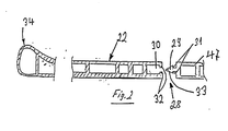
- Fig. 2 ein Detail (Revisionsdeckel) des Rolladenkastens nach Fig. 1 im Querschnitt und vergrößertem Maßstab; und
- Fig. 3 ein weiteres Detail des erfindungsgemäßen Rolladenkastens, nämlich eine diesem zugeordnete Führungsschiene im Querschnitt.
- 1 shows a roller shutter box designed according to the invention in a perspective cross-sectional illustration;
- FIG. 2 shows a detail (inspection cover) of the roller shutter box according to FIG. 1 in cross section and on an enlarged scale; and
- Fig. 3 shows a further detail of the roller shutter box according to the invention, namely a cross-section of a guide rail associated therewith.
Der in Fig. 1 dargestellte Rolladenkasten 10 umfaßt einen im Querschnitt etwa U-förmig ausgebildeten, einen Rolladen-Aufnahmeraum bzw. Rollraum 11 begrenzenden Kastenkörper 12 aus Polystyrol-Hartschaum, dessen die Außenwand 13 und Innenwand 14 definierenden Schenkel an den Außenseiten jeweils mit einer als Putzträger dienenden Leichtbauplatte 15, 16 verkleidet sind. Innerhalb des Rollraums 11 ist in herkömmlicher Weise ein Rolladen 17 auf- und abwickelbar. Die Wickelachse ist in Fig. 1 mit der Bezugsziffer 18 gekennzeichnet. Die Leichtbauplatten 15, 16 bestehen aus zementgebundener Holzwolle und sind an den entsprechenden Außenseiten des Kastenkörpers angeschäumt. Der so ausgebildete Kastenkörper 12 ist mittels eines Rippenstahlgewebes 19 armiert, wobei im oberen Bereich des Kastenkörpers das Rippenstahlgewebe 19 teilweise freigelegt ist unter Ausbildung einer Sturzverankerung 20. Das Rippenstahlgewebe wird vorzugs weise aus Rippenstahl-Stäben mit einem Durchmesser von etwa 4 mm gebildet. Der beschriebene Kastenkörper wird in der Regel als etwa 6 m langer Korpus bereitgestellt. Fachhändler fertigen dann aus diesem 6-Meter-Element maßgenaue Rolladenkästen, deren Stirnseiten unter entsprechendem Abschluß des Rollraums 11 vor der Montage verblendet werden, z. B. mittels entsprechend zugeschnittenen Spanholz-Platten oder dgl.The roller shutter box 10 shown in FIG. 1 comprises a
Die im montierten Zustand des Rolladenkastens 10 offene Unterseite des U-förmig ausgebildeten Kastenkörpers 12 ist durch ein an der Innenwand 14 desselben befestigtes Verschlußteil 21 und einen unmittelbar an diesen anschließenden Revisionsdeckel 22 verschlossen, der sich unter Freilassung eines Rolladenaustrittschlitzes 23 bis nahe an die Innenseite 24 der Außenwand 13 des Kastenkörpers 12 erstreckt. An dieser Stelle sei erwähnt, daß die Außenwand 13 sowie die Innenwand 14 des Kastenkörpers 12 jeweils etwa mit der Außenseite bzw. Innenseite einer Gebäudewand fluchtet, in die der beschriebene Rolladenkasten oberhalb eines Fenster- oder Türstocks 25 eingesetzt wird. Das bzw. die dem Fenster- oder Türstock 25 zugeordnete Fenster bzw. Tür ist in Fig. 1 mit der Bezugsziffer 26 gekennzeichnet.The underside of the U-shaped
Der Revisionsdeckel 22 ist also unmittelbar am Verschlußteil 21 befestigt, welches ebenfalls aus Polystyrol-Hartschaum hergestellt und an der dem Innenraum des Gebäudes oder dgl. zugewandten Außenseite ähnlich wie die Außenseite der Innenwand 14 des Kastenkörpers 12 mit einer als Putzträger dienenden Leichtbauplatte 27 aus zementgebundener Holzwolle verkleidet ist. Durch das so ausgebildete Verschlußteil 21, das sich über die gesamte Länge des Kastenkörpers 12 erstreckt, wird eine wirksame Schall- und Wärmedämmung auch im innengelegenen Eckbereich des Rolladenkastens 10 erreicht. Das Ver schlußteil 21 wird vor der Montage des Rolladenkastens 10 an der Innenwand 14 des Kastenkörpers 12 befestigt, vorzugsweise dauerhaft befestigt, insbesondere angeklebt.The
Wie insbesondere Fig. 2 erkennen läßt, ist der Revisionsdeckel 22 mittels einer Rastverbindung 28 lösbar am Verschlußteil 21 befestigt. Die Rastverbindung wird durch einen am Verschlußteil 21 angeordneten und sich über die gesamte Länge desselben erstreckenden Rastvorsprung 29 sowie eine am Revisionsdeckel 22 komplementär ausgebildete Rastaufnahme 30 gebildet. Es handelt sich um eine Art Nut-/Feder-Verbindung zwischen Revisionsdeckel 22 und Verschlußteil 21. Der Rastvorsprung 29 weist einen pfeilartigen Querschnitt mit Hinterschneidungen 31 auf, die von entsprechenden Vorsprüngen 32 der Rastaufnahme 30 hintergriffen werden. Zum erleichterten Ein- bzw. Ausrasten der Rastverbindung 28 können die Flanken 33 des pfeilartigen Rastvorsprunges 29 geringfügig konvex gewölbt sein. Des weiteren sind die die Hinterschneidungen 31 begrenzenden Flanken vorzugsweise geringfügig nach vorne, d. h. zur Pfeilspitze hin geneigt. Auf diese Weise läßt sich die Rastverbindung 28 bei Abnahme des Revisionsdeckels 22 unter Abkippen desselben um die Rastverbindung 28 nach unten ohne großen Kraftaufwand lösen. In entsprechender Weise, d. h. bei umgekehrtem Bewegungsablauf, läßt sich die Rastverbindung wieder sehr leicht herstellen. Insofern handelt es sich bei der beschriebenen Gestaltung des Rastvorsprunges 29 durchaus bedeutende Maßnahmen, die die Montage bzw. Demontage des Revisionsdeckels 22 ganz erheblich erleichtern.As can be seen in particular in FIG. 2, the
Im dargestellten Fall erstrecken sich der Rastvorsprung 29 sowie die komplementäre Rastaufnahme 30 etwa parallel zur Flachseite des Revisionsdeckels 22. Grundsätzlich wäre es auch denkbar, den Rastvorsprung 29 nach unten gerichtet auszubilden. Die Rastaufnahme 30 müßte dann nach oben hin geöffnet sein. Ferner ist es denkbar, den Rastvorsprung 29 am Revisionsdeckel 22 und die Rastaufnahme 30 am Verschlußteil 21 anzubringen.In the illustrated case, the locking projection 29 and the
Der Revisionsdeckel 22 weist an seiner dem Rolladen-Austrittschlitz 23 zugewandten Seite einen als Abroll-Traverse dienenden Wulst, nämlich Gleitwulst 34, auf.The
Damit der Revisionsdeckel 22 auch bei stärkerer Belastung, insbesondere durch den auf- und abbewegten Rolladen 17, sicher in seiner vorgegebenen Position gehalten ist, sind dem Revisionsdeckel stirnseitig zusätzlich Haltewinkel (nicht dargestellt) zugeordnet, an deren Unterseite der Revisionsdeckel 22 mittels den Revisionsdeckel durchdringende Schrauben oder dgl. anschließbar ist. Diese Schrauben müssen natürlich vor Abnahme des Revisionsdeckels 22 gelöst werden. Die Montage bzw. Demontage des Revisionsdeckels wird dadurch nur unwesentlich erschwert.So that the
Von besonderem Interesse, auch unabhängig von der beschriebenen Ausbildung des Rolladenkastens 10, sind die diesem zugeordneten Führungsschienen 35, wie eine in Fig. 3 dargestellt ist, und zwar in Zuordnung zum Fenster- bzw. Türstock 25. Konkret ist die dargestellte Führungsschiene 35 als H-Profil ausgebildet. Dadurch läßt sich unter Anschluß an das Mauerwerk 36 bzw. den Verputz 37 desselben ein allseitig geschlossener Hohlraum 38 bilden, in den ein Schenkel 39 eines unter Putz angeordneten Befestigungswinkels 40 einführbar ist. Auf diese Weise ist der Befestigungswinkel 40 von außen her nicht sichtbar. Befestigungswinkel 40 sowie Führungsschine 35 bestehen vorzugsweise aus Aluminium. Die eigentliche Laufschiene 41 ist innenseitig in herkömmlicher Weise mit Gummiködern bzw. Bürstendichtungen 42 versehen.Of particular interest, regardless of the design of the roller shutter box 10 described, are the associated
Die Befestigungswinkel 40, von denen je nach Länge der Führungsschiene 35 mehr oder weniger vorgesehen werden müssen, sind an der Mauer 36 mittels einer Justierschrau be 43 befestigt derart, daß der Abstand der Befestigungswinkel von der Mauer 36 jeweils einstellbar ist. Darüber hinaus weist der an der Mauer 36 anschließbare Schenkel 44 des Befestigungswinkels 40 ein sich in Richtung seiner Längserstreckung erstreckendes Langloch (nicht dargestellt) auf, durch das die Justierschraube 43 hindurchgeführt ist. Auf diese Weise läßt sich der Abstand der Führungsschiene 35 vom Fenster- bzw. Türstock 25 genau einstellen.The mounting
Ähnlich kann der an die Führungsschiene 35 anzuschließende bzw. vom Mauerwerk 36 abstehende Schenkel 39 des Befestigungswinkels 40 ein sich in Längserstreckung dieses Schenkels 39 erstreckendes Langloch aufweisen (ebenfalls nicht dargestellt), durch das hindurch eine Schienen-Befestigungsschraube 45 hindurchführbar ist. Damit ist die Führungsschiene 35 auch in Richtung etwa senkrecht zur Mauer 36 zusätzlich justierbar derart, daß sie stets stumpf mit dem Verputz 37 abschließt.Similarly, the leg 39 of the mounting
Schließlich weisen die aneinanderliegenden Flächen von Führungsschiene 35 und Befestigungswinkel 40 jeweils eine sich in Richtung der Längserstreckung der Führungsschiene 35 erstreckende Rippenprofilierung 46 auf. Dadurch wird die Montage der Führungsschiene 35 erleichtert.Finally, the adjoining surfaces of the
Die Gummiköder 42 können natürlich auch durch herkömmliche Bürstenbänder ersetzt werden, die ebenfalls geräuschdämpfend wirken.The rubber baits 42 can of course also be replaced by conventional brush tapes, which also have a noise-dampening effect.
Abschließend sei noch erwähnt, daß - wie auch Fig. 1 erkennen läßt - der Revisionsdeckel zwar außerhalb des Fensters 26, jedoch innerhalb der Mauerleibung liegt. Konkret besteht der Revisionsdeckel 22 aus wetterfestem, hochbeständigem PVC-Material. Er ist in der dargestellten Weise als Strangprofil herstellbar.Finally, it should also be mentioned that - as can also be seen in FIG. 1 - the inspection cover is outside the
Aufgrund des gegenüber dem Rolladen 17 zurückgesetzten Fensters 26 entsteht ein besonders günstiger Windwinkel, wodurch dem Isolierglas weniger Wärme entzogen wird. Darüber hinaus wird dadurch eine zusätzliche Wärme- und Schalldämmung bei geschlossenem Rolladen erhalten.Because the
Der beschriebene Rolladenkasten eignet sich für 24/30/36er Mauerwerk. Ein Mauerversatz muß dabei nicht hingenommen werden.The roller shutter box described is suitable for 24/30/36 masonry. A wall offset does not have to be accepted.
Zurückkommend auf die Ausbildung des Verschlußteils 21 sei darauf hingewiesen, daß bei der dargestellten Ausführungsform der Rastvorsprung 29 integraler Bestandteil eines an der Unterseite des Verschlußteils 21 befestigten Profilkörpers 47 ist, wobei dessen Unterseite mit der Unterseite des Verschlußteils 21 bzw. mit der Unterseite der Leichtbauplatte 27 bündig ist. Der Profilkörper 7 ist an die Unterseite des Verschlußteiles 21 angeklebt und bildet zugleich die Stützfläche für den Rolladenkasten auf dem Fenster- bzw. Türstock 25. Die Breite des Profilkörpers 47 ist jedoch etwas geringer als die Breite des Fenster- bzw. Türstocks 25, um zu vermeiden, daß durch den Profilkörper 47 eine Kältebrücke entsteht. Dadurch, daß der Profilkörper 47 als Hohlprofilkörper ausgebildet ist, ist er jedoch selbst gut wärme- und schalldämmend. Vorzugsweise erfolgt die Befestigung des beschriebenen Rolladenkastens 10 am Fenster- bzw. Türstock über den Hohlprofilkörper 47 derart, daß ein Eindringen von Kaltluft in den Innenraum zwischen Rolladenkasten 10 und Fenster- bzw. Türstock 25 sicher vermieden ist. Zu diesem Zweck kann zwischen dem Rolladenkasten 10 und der Oberseite des Fenster- bzw. Türstocks 25 noch eine zusätzliche Dichtung vorgesehen sein.Returning to the design of the
Selbstverständlich kann das Verschlußteil 21 auch integraler Bestandteil des Rolladenkastens 12 sein. Grundsätzlich ist auch denkbar, daß bei entsprechender Positionierung des Rolladenkastens gegenüber dem Fensterbzw. Türstock 25 der äußere Revisionsdeckel 22 unmittelbar an der Innenwand 14 des Kastenkörpers 12 in der oben beschriebenen Weise anschließbar ist.Of course, the
Sämtliche in den Unterlagen offenbarten Merkmale werden als erfindungs- bzw. neuerungswesentlich beansprucht, soweit sie einzeln oder in Kombination gegenüber dem Stand der Technik neu sind.All features disclosed in the documents are claimed as essential to the invention or innovation, insofar as they are new compared to the prior art, individually or in combination.
Claims (14)
dadurch gekennzeichnet, daß der Revisionsdeckel (22) unmittelbar am unteren Verschlußteil (21) befestigt ist, und zwar mittels einer lösbaren Rastverbindung (28).1. Roller shutter box with an approximately U-shaped cross section, a roller shutter receiving space (rolling space 11) delimiting box body (12) made of polystyrene or the like. Hard foam, the outer (13) - and inner (14) wall defining Legs are each provided on the outside with a layer serving as a plaster base, in particular in the form of a lightweight board (15, 16) made of cement-bonded wood wool, the open underside of the U-shaped box body (12) being provided by a wall (14) on the inside wall. same fastened closure part (21) and in continuation of the same ben is closed by an inspection cover (22) which is removable from the outside in the assembled state of the roller shutter box and which extends to close to the inside (24) of the outer wall (13) of the box body (12), leaving a roller shutter exit slot (23) free,
characterized in that the inspection cover (22) is fastened directly to the lower closure part (21) by means of a releasable latching connection (28).
Applications Claiming Priority (2)
| Application Number | Priority Date | Filing Date | Title |
|---|---|---|---|
| DE19863628238 DE3628238A1 (en) | 1986-08-20 | 1986-08-20 | SHUTTER BOX |
| DE3628238 | 1986-08-20 |
Publications (2)
| Publication Number | Publication Date |
|---|---|
| EP0257547A2 true EP0257547A2 (en) | 1988-03-02 |
| EP0257547A3 EP0257547A3 (en) | 1989-04-12 |
Family
ID=6307781
Family Applications (1)
| Application Number | Title | Priority Date | Filing Date |
|---|---|---|---|
| EP87112043A Withdrawn EP0257547A3 (en) | 1986-08-20 | 1987-08-19 | Roller shutter box |
Country Status (2)
| Country | Link |
|---|---|
| EP (1) | EP0257547A3 (en) |
| DE (1) | DE3628238A1 (en) |
Cited By (3)
| Publication number | Priority date | Publication date | Assignee | Title |
|---|---|---|---|---|
| GB2242923A (en) * | 1990-03-12 | 1991-10-16 | Kedzia Krystyna Irena | Roller-shutter housing assembly |
| EP0740045A2 (en) * | 1995-04-28 | 1996-10-30 | Johann Henkenjohann | Shutter box |
| GB2351753A (en) * | 1999-04-22 | 2001-01-10 | Isotra S R O | A carrier for a blind mechanism |
Families Citing this family (6)
| Publication number | Priority date | Publication date | Assignee | Title |
|---|---|---|---|---|
| DE3725606C2 (en) * | 1987-08-01 | 1996-05-15 | Helmut Lehr | Roller shutter box and process for its manufacture |
| DE19908571C2 (en) * | 1999-02-27 | 2002-01-17 | Sks Stakusit Bautechnik Gmbh | shutters aggregate |
| DE10101910A1 (en) * | 2001-01-16 | 2002-07-18 | Helmut Lehr Rolladenkasten | Shutter box |
| DE10326015A1 (en) * | 2003-05-29 | 2004-12-30 | Saint-Gobain Weber Gmbh | Building wall construction with roller shutter box with thermal insulation panels |
| EP2325433A2 (en) | 2009-11-20 | 2011-05-25 | Alltec GmbH | Box for holding a shade for a window or a door and method for producing such a box |
| DE202019002886U1 (en) * | 2019-07-05 | 2020-09-04 | Hans-Peter Häusel | Roller shutter box insulation system for roller shutters that are installed in the wall |
Citations (5)
| Publication number | Priority date | Publication date | Assignee | Title |
|---|---|---|---|---|
| DE1977983U (en) * | 1967-11-04 | 1968-02-01 | Kubi Jalousie G M B H & Co K G | TWO-PIECE ROLLER SHUTTER SIDE GUIDE PROFILE WITH SWIVELING AND ADJUSTMENT AREA. |
| DE2004668A1 (en) * | 1970-02-03 | 1971-08-12 | Schmitz, Josef, 4050 Monchenglad bach | Lateral guide for roller shutters |
| DE3129994A1 (en) * | 1981-07-29 | 1983-03-03 | Karl Bachl Ziegel- und Betonwerke, 8391 Deching | Roller-blind casing and process for the production thereof |
| DE8613285U1 (en) * | 1986-05-16 | 1986-07-03 | Staudt, Erwin, 8751 Sulzbach | Shutter window element |
| DE8622304U1 (en) * | 1986-08-20 | 1986-10-02 | Bohn, Alfred, 6927 Bad Rappenau | Shutter box |
-
1986
- 1986-08-20 DE DE19863628238 patent/DE3628238A1/en not_active Withdrawn
-
1987
- 1987-08-19 EP EP87112043A patent/EP0257547A3/en not_active Withdrawn
Patent Citations (5)
| Publication number | Priority date | Publication date | Assignee | Title |
|---|---|---|---|---|
| DE1977983U (en) * | 1967-11-04 | 1968-02-01 | Kubi Jalousie G M B H & Co K G | TWO-PIECE ROLLER SHUTTER SIDE GUIDE PROFILE WITH SWIVELING AND ADJUSTMENT AREA. |
| DE2004668A1 (en) * | 1970-02-03 | 1971-08-12 | Schmitz, Josef, 4050 Monchenglad bach | Lateral guide for roller shutters |
| DE3129994A1 (en) * | 1981-07-29 | 1983-03-03 | Karl Bachl Ziegel- und Betonwerke, 8391 Deching | Roller-blind casing and process for the production thereof |
| DE8613285U1 (en) * | 1986-05-16 | 1986-07-03 | Staudt, Erwin, 8751 Sulzbach | Shutter window element |
| DE8622304U1 (en) * | 1986-08-20 | 1986-10-02 | Bohn, Alfred, 6927 Bad Rappenau | Shutter box |
Cited By (6)
| Publication number | Priority date | Publication date | Assignee | Title |
|---|---|---|---|---|
| GB2242923A (en) * | 1990-03-12 | 1991-10-16 | Kedzia Krystyna Irena | Roller-shutter housing assembly |
| GB2242923B (en) * | 1990-03-12 | 1993-12-01 | Kedzia Krystyna Irena | Roller-shutter assembly |
| EP0740045A2 (en) * | 1995-04-28 | 1996-10-30 | Johann Henkenjohann | Shutter box |
| EP0740045A3 (en) * | 1995-04-28 | 1998-04-08 | Johann Henkenjohann | Shutter box |
| GB2351753A (en) * | 1999-04-22 | 2001-01-10 | Isotra S R O | A carrier for a blind mechanism |
| GB2351753B (en) * | 1999-04-22 | 2003-02-12 | Isotra S R O | Profiled carrier for the reception of a driving mechanism for controlling of louvres |
Also Published As
| Publication number | Publication date |
|---|---|
| EP0257547A3 (en) | 1989-04-12 |
| DE3628238A1 (en) | 1988-03-10 |
Similar Documents
| Publication | Publication Date | Title |
|---|---|---|
| EP0932742B1 (en) | Door or window element | |
| EP0257547A2 (en) | Roller shutter box | |
| DE8622304U1 (en) | Shutter box | |
| DE2130023C2 (en) | Plastics door or window frame - has groove between external chamber containing metal reinforcement and two inner chambers | |
| DE3817775A1 (en) | Design for casing-in bay window soffit - has casing panel with edges connected by push fit to profile on window frame and angle profile embracing window opening corner | |
| EP0918127B1 (en) | Door case and mounting device | |
| DE3202508C2 (en) | ||
| DE10361123B4 (en) | Lost formwork for holding a shutter or a blind | |
| AT394419B (en) | SHUTTER BOX | |
| DE3202833A1 (en) | Facing for a frame fastened in a building and intended for a room door or house door or the like | |
| DE3800446C2 (en) | Profile strip for the erection of partitions and the like, in particular for shower or bathtub partitions | |
| DE2117645A1 (en) | Door frame with wall closure provided on both sides | |
| DE3918872A1 (en) | Roller-blind casing | |
| AT398111B (en) | SHUTTER | |
| EP1041236A2 (en) | Roller shutter box | |
| DE2839748A1 (en) | Plastics roller shutter guidance rail - with U=profile for guiding armour, hard PVC front portion and soft PVC buffer strip | |
| DE2125272A1 (en) | Ready-to-install sliding door arrangement | |
| DE8218308U1 (en) | SHUTTER BOX | |
| DE2302291A1 (en) | PRE-FABRICATED ELEMENT FOR INSTALLATION IN WALL PERFORMANCE | |
| DE6934397U (en) | THERMAL INSULATED DOOR OR COVER LOCKING FOR REFRIGERATED FURNITURE. | |
| CH510194A (en) | Built-in door | |
| DE3200261A1 (en) | Securing means for windows and doors of an assembly building consisting of prefabricated parts | |
| EP1757768A2 (en) | Plane construction element for partition walls | |
| DE7414512U (en) | Device for fixing door frames and the like | |
| DE102019135251A1 (en) | Drywall support frame for a soundproof sliding door |
Legal Events
| Date | Code | Title | Description |
|---|---|---|---|
| PUAI | Public reference made under article 153(3) epc to a published international application that has entered the european phase |
Free format text: ORIGINAL CODE: 0009012 |
|
| AK | Designated contracting states |
Kind code of ref document: A2 Designated state(s): AT BE CH DE FR LI NL |
|
| PUAL | Search report despatched |
Free format text: ORIGINAL CODE: 0009013 |
|
| AK | Designated contracting states |
Kind code of ref document: A3 Designated state(s): AT BE CH DE FR LI NL |
|
| 17P | Request for examination filed |
Effective date: 19890518 |
|
| 17Q | First examination report despatched |
Effective date: 19891227 |
|
| STAA | Information on the status of an ep patent application or granted ep patent |
Free format text: STATUS: THE APPLICATION IS DEEMED TO BE WITHDRAWN |
|
| 18D | Application deemed to be withdrawn |
Effective date: 19910503 |
|
| RIN1 | Information on inventor provided before grant (corrected) |
Inventor name: BOHN, ALFRED |