EP0256958A2 - Stackable chair with an inclinable back rest - Google Patents
Stackable chair with an inclinable back rest Download PDFInfo
- Publication number
- EP0256958A2 EP0256958A2 EP87420212A EP87420212A EP0256958A2 EP 0256958 A2 EP0256958 A2 EP 0256958A2 EP 87420212 A EP87420212 A EP 87420212A EP 87420212 A EP87420212 A EP 87420212A EP 0256958 A2 EP0256958 A2 EP 0256958A2
- Authority
- EP
- European Patent Office
- Prior art keywords
- backrest
- armrests
- legs
- armrest
- seat
- Prior art date
- Legal status (The legal status is an assumption and is not a legal conclusion. Google has not performed a legal analysis and makes no representation as to the accuracy of the status listed.)
- Withdrawn
Links
Images


Classifications
-
- A—HUMAN NECESSITIES
- A47—FURNITURE; DOMESTIC ARTICLES OR APPLIANCES; COFFEE MILLS; SPICE MILLS; SUCTION CLEANERS IN GENERAL
- A47C—CHAIRS; SOFAS; BEDS
- A47C3/00—Chairs characterised by structural features; Chairs or stools with rotatable or vertically-adjustable seats
- A47C3/04—Stackable chairs; Nesting chairs
-
- A—HUMAN NECESSITIES
- A47—FURNITURE; DOMESTIC ARTICLES OR APPLIANCES; COFFEE MILLS; SPICE MILLS; SUCTION CLEANERS IN GENERAL
- A47C—CHAIRS; SOFAS; BEDS
- A47C1/00—Chairs adapted for special purposes
- A47C1/02—Reclining or easy chairs
- A47C1/022—Reclining or easy chairs having independently-adjustable supporting parts
- A47C1/024—Reclining or easy chairs having independently-adjustable supporting parts the parts, being the back-rest, or the back-rest and seat unit, having adjustable and lockable inclination
- A47C1/026—Reclining or easy chairs having independently-adjustable supporting parts the parts, being the back-rest, or the back-rest and seat unit, having adjustable and lockable inclination by means of peg-and-notch or pawl-and-ratchet mechanism
- A47C1/0265—Reclining or easy chairs having independently-adjustable supporting parts the parts, being the back-rest, or the back-rest and seat unit, having adjustable and lockable inclination by means of peg-and-notch or pawl-and-ratchet mechanism positioned under the arm-rests
Definitions
- the present invention relates to armchairs, in particular for outdoor use, in which the backrest is articulated by its base at the rear of the seat in order to allow it to be adjusted in inclination, the blocking being ensured by means of a rack mechanism associated with each of the articulated armrests.
- the invention aims to allow the realization of a chair of the aforementioned kind which is capable of being stacked in a relatively small footprint in order to facilitate its transport, storage and storage.
- the armchair according to the invention comprises a seat which is rigidly supported by four profiled feet and arranged to allow the interpenetration of the feet of two superimposed armchairs, while the armrests are established at a length such that at least one of the inclinations imparted to the backrest by the rack-and-pinion locking mechanisms associated with the said armrests, the anterior end of the latter being recessed with respect to the anterior face of the front legs of the chair.
- the reference 1 designates the seat rigidly supported by two front legs 2 and two rear legs 3. It will be observed that in the usual manner in stackable seats, each leg 2 or 3 present in section transverse a V-shaped profile, suitable for allowing interlocking, and that in addition the upper outlet of the rear legs 3 is recessed inwardly relative to the corresponding outer edge of the seat 1.
- this seat 1 is associated with a reclining backrest 4, the base thereof and the rear part of the seat comprising knuckles or ears 5 assembled in pairs to allow the backrest 4 to pivot along a horizontal axis 6.
- each armrest 8 In the back 4 are articulated in 7 two lateral armrests 8, oriented substantially horizontally. In addition to their support function for the user's elbows, these armrests, according to a conventional arrangement, simultaneously constitute bodies for immobilizing the backrest 4 to any one of a series of different inclinations.
- the underside of each armrest 8 has a rack toothing 9 capable of coming to cooperate selectively with a fixed tooth 10 provided at the end of a bent portion 11 which extends upwards, with the same profile in section, each front leg 2 above the seat 1; it will be observed that each bent part 11 is advantageously stiffened by a vertical veil 12 which connects it laterally to the seat 1.
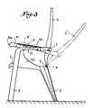
- Fig. 3 highlights the adjustment in inclination of the backrest 4.
- 4 and 8 on the one hand, 4 ⁇ and 8 ⁇ on the other hand, the two orien extreme positions of the backrest and armrests, and it is understood that if the teeth 9 are provided with four teeth, there are still two intermediate positions.
- Each of the armrests 8 of the chair is set at a length such that at one or less of the different inclinations of the backrest 4, its anterior face (referenced 8 a in fig. 4) is located set back from the line XY corresponding to the front face of the front leg 2 and the bent part 11 on the side considered of the chair.
- two armchairs of the same type may be stacked in the manner illustrated in FIG. 4, the horizontal branch of each of the bent parts 11 of the upper chair coming to be placed immediately above the corresponding armrest 8 of the lower chair, while the legs 2 and 3 interpenetrate; pinching the outlets of the rear legs 3 allowing the feet 3 of the upper chair to escape from the armrests 8 of the lower chair, a series of chairs according to the invention can thus be stacked in a reduced space.
- the feet may have in cross section any profile suitable for allowing nesting, for example in the form of U or L.
- bent portions 11 which are intended to support the fixed teeth 10 of the locking mechanisms can be replaced by vertical edges made laterally integral with the seat 1, the latter then having a general profile in the form of a bowl or basket.
- each lateral armrest 8 is formed by two complementary parts, namely the upper horizontal branch 111 a of each bent part 111, and a movable element 108 articulated at 7 in the backrest 4.
- Each of the two elements 108 has a cross section a U-shaped profile open towards the bottom, so as to overlie the overlapping branch 111a corresponding.
- each element 108 is associated with a lock 13 movable vertically along a rod 14 secured to the underside of said element 108.
- a spring 15 or other elastic means tends to maintain a tooth 13 a of the lock 13 selectively engaged in one of a series of notches 111 b which open laterally in a lumen 111 c provided longitudinally in the branch 111 a .
- the two elements 108 are rigidly assembled to the bent portions 111, thereby ensuring the immobilization of the backrest 4 at the chosen inclination.
- the armchairs may be stacked at any one of the different inclined positions of the backrest 4 since the ends of the armrests 8 are always set back with respect to the front side of the aforementioned feet.
Abstract
Description
La présente invention a trait aux fauteuils, notamment pour usage extérieur, dans lequel le dossier est articulé par sa base à l'arrière de l'assise afin d'en permettre le réglage en inclinaison, le blocage étant assuré à l'aide d'un mécanisme de crémaillière associé à chacun des accoudoirs articulés.The present invention relates to armchairs, in particular for outdoor use, in which the backrest is articulated by its base at the rear of the seat in order to allow it to be adjusted in inclination, the blocking being ensured by means of a rack mechanism associated with each of the articulated armrests.
L'invention a pour but de permettre la réalisation d'un fauteuil du genre susvisé qui soit susceptible d'être empilé sous un encombrement relativement réduit en vue de faciliter son transport, son stockage et son rangement.The invention aims to allow the realization of a chair of the aforementioned kind which is capable of being stacked in a relatively small footprint in order to facilitate its transport, storage and storage.
Le fauteuil suivant l'invention comporte une assise qui est rigidement supportée par quatre pieds profilés et disposés pour permettre l'interpénétration des pieds de deux fauteuils superposés, tandis que les accoudoirs sont établis à une longueur telle qu'à l'une au moins des inclinaisons conférées au dossier par les mécanismes de blocage à crémaillère associés auxdits accoudoirs, l'extrémité antérieure de ces derniers est disposée en retrait par rapport à la face antérieure des pieds antérieurs du fauteuil.The armchair according to the invention comprises a seat which is rigidly supported by four profiled feet and arranged to allow the interpenetration of the feet of two superimposed armchairs, while the armrests are established at a length such that at least one of the inclinations imparted to the backrest by the rack-and-pinion locking mechanisms associated with the said armrests, the anterior end of the latter being recessed with respect to the anterior face of the front legs of the chair.
Le dessin annexé, donné à titre d'exemple, permettra de mieux comprendre l'invention, les caractéristiques qu'elle présente et les avantages qu'elle est susceptible de procurer :
- Fig. 1 est une vue en perspective montrant de manière schématique un fauteuil établi conformément à une première forme de mise en oeuvre de la présente invention.
- Fig. 2 reproduit fig. 1, les différents éléments constitutifs du fauteuil étant toutefois représentés préalablement à leur montage.
- Fig. 3 est une vue de côté avec arrachement, illustrant le réglage en inclinaison du dossier et le blocage assuré par les accoudoirs.
- Fig. 4 est une vue de côté représentant trois fauteuils identiques à celui de fig. 1 à 3, supposés amenés à la position d'empilage.
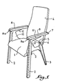
- Fig. 5 illustre en perspective, à l'état démonté, une seconde forme de mise en oeuvre de l'invention.
- Fig. 6 est une vue de côté montrant l'ensemble de l'un des accoudoirs à l'état monté.
- Fig. 7 est une coupe transversale à plus grande échelle, suivant le plan indiqué en VII-VII en fig. 6.
- Fig. 8 est une coupe horizontale suivant VIII-VIII (fig. 7).
- Fig. 9 et 10 sont des coupes analogues à celles de fig. 7 et 8, le verrou étant supposé en cours de manoeuvre.
- Fig. 1 is a perspective view schematically showing an armchair established in accordance with a first embodiment of the present invention.
- Fig. 2 reproduced fig. 1, the various components of the chair, however, being shown prior to assembly.
- Fig. 3 is a side view with parts broken away, illustrating the inclination adjustment of the backrest and the locking provided by the armrests.
- Fig. 4 is a side view showing three armchairs identical to that of FIG. 1 to 3, assumed to be brought to the stacking position.
- Fig. 5 illustrates in perspective, in the disassembled state, a second embodiment of the invention.
- Fig. 6 is a side view showing the assembly of one of the armrests in the assembled state.
- Fig. 7 is a cross section on a larger scale, along the plane indicated in VII-VII in FIG. 6.
- Fig. 8 is a horizontal section along VIII-VIII (fig. 7).
- Fig. 9 and 10 are sections similar to those of FIG. 7 and 8, the lock being assumed to be in the course of operation.
Sur l'ensemble du dessin, la référence 1 désigne l'assise supportée de manière rigide par deux pieds antérieurs 2 et deux pieds arrière 3. On observera qu'à la manière usuelle dans les sièges empilables, chaque pied 2 ou 3 présente en section transversale un profil en forme de V, propre à permettre l'emboîtement, et qu'en outre le débouché supérieur des pieds arrière 3 est disposé en retrait vers l'intérieur par rapport au bord extérieur correspondant de l'assise 1. A cette assise 1 est associé un dossier inclinable 4, la base de celui-ci et la partie arrière de l'assise comportant des charnons ou oreilles 5 assemblés deux à deux pour autoriser le pivotement du dossier 4 suivant un axe horizontal 6.Throughout the drawing, the
Au dossier 4 sont articulés en 7 deux accoudoirs latéraux 8, orientés de manière substantiellement horizontale. Outre leur fonction de soutien pour les coudes de l'usager, ces accoudoirs, suivant une disposition classique, constituent simultanément organes pour l'immobilisation du dossier 4 à l'une quelconque d'une série d'inclinaisons différentes. Dans la forme de réalisation suivant fig. 1 à 5, la face inférieure de chaque accoudoir 8 comporte une denture de crémaillère 9 apte à venir coopérer sélectivement avec une dent fixe 10 prévue en bout d'une partie coudée 11 qui prolonge vers le haut, avec le même profil en section, chaque pied antérieur 2 au-dessus de l'assise 1 ; on observera que chaque partie coudée 11 est avantageusement raidie par un voile vertical 12 qui la relie latéralement à l'assise 1.In the
Fig. 3 fait bien ressortir le réglage en inclinaison du dossier 4. On a représenté en 4 et 8 d'une part, 4ʹ et 8ʹ d'autre part, les deux orien tations extrêmes du dossier et des accoudoirs, et l'on comprend que si les dentures 9 sont pourvues de quatre dents, il existe encore deux positions intermédiaires.Fig. 3 highlights the adjustment in inclination of the
Chacun des accoudoirs 8 du fauteuil est établi à une longueur telle qu'à l'une ou moins des différentes inclinaisons du dossier 4, sa face antérieure (référencée 8a en fig. 4) se trouve située en retrait par rapport à la ligne X-Y correspondant à la face antérieure du pied avant 2 et de la partie coudée 11 du côté considéré du fauteuil.Each of the
Dans ces conditions, deux fauteuils du même type sont susceptibles d'être empilés à la manière illustrée en fig. 4, la branche horizontale de chacune des parties coudées 11 du fauteuil supérieur venant se disposer immédiatement au-dessus de l'accoudoir correspondant 8 du fauteuil inférieur, tandis que les pieds 2 et 3 s'interpénètrent ; le pinçage des débouchés des pieds arrières 3 permettant aux pieds 3 du fauteuil supérieur d'échapper aux accoudoirs 8 du fauteuil inférieur, on peut ainsi empiler sous un encombrement réduit une série de fauteuils suivant l'invention.Under these conditions, two armchairs of the same type may be stacked in the manner illustrated in FIG. 4, the horizontal branch of each of the
On conçoit que les pieds peuvent présenter en section transversale tout profil propre à permettre l'emboîtement, par exemple en forme de U ou de L. Au surplus, les parties coudées 11 qui sont destinées à supporter les dents fixes 10 des mécanismes de blocage peuvent être remplacées par des rebords verticaux rendus latéralement solidaires de l'assise 1, celle-ci présentant alors un profil général en forme de cuvette ou de corbeille.It is understood that the feet may have in cross section any profile suitable for allowing nesting, for example in the form of U or L. In addition, the
Dans la forme de réalisation suivant fig. 5 à 10, chaque accoudoir latéral 8 est formé par deux pièces complémentaires, à savoir la branche horizontale supérieure 111a de chaque partie coudée 111, et un élément mobile 108 articulé en 7 au dossier 4. Chacun des deux éléments 108 présente en section transversale un profil en forme de U ouvert en direction du bas, de façon à venir recouvrir à chevauchement la branche 111a correspondante.In the embodiment according to fig. 5 to 10, each
Comme illustré en fig. 7 à 10, à chaque élément 108 est associé un verrou 13 mobile verticalement le long d'une tige 14 solidaire de la face inférieure dudit élément 108. Un ressort 15 ou autre moyen élastique tend à maintenir une dent 13a du verroU 13 engagée sélectivement dans l'une d'une série d'encoches 111b qui débouchent latéralement dans une lumière 111c prévue longitudinalement dans la branche 111a.As illustrated in fig. 7 to 10, each
A la position engagée des dents 13a telle qu'illustrée en fig. 7 et 8, les deux éléments 108 sont rigidement assemblés aux parties coudées 111 en assurant de la sorte l'immobilisation du dossier 4 à l'inclinaison choisie. Pour modifier cette inclinaison, il suffit à l'utisateur de presser les verrous vers le haut et de soulever les éléments 108 pour dégager les dents 13a et, après glissement de chaque éléments 108 le long de la branche 111a, rabattre l'ensemble vers le bas afin d'introduire chacune des dents précitées dans une autre encoche 111b.In the engaged position of the
On conçoit que si les parties coudées 111 sont bien disposées dans le prolongement des pieds avant 2, les fauteuils sont susceptibles d'être empilés à l'une quelconque des différentes positions inclinées du dossier 4 puisque les extrémités des accoudoirs 8 sont toujours situées en retrait par rapport à la face antérieure des pieds précités.It is understood that if the
Claims (3)
Applications Claiming Priority (2)
| Application Number | Priority Date | Filing Date | Title |
|---|---|---|---|
| FR8611551A FR2602408A1 (en) | 1986-08-06 | 1986-08-06 | STACKABLE ARMCHAIR WITH ADJUSTABLE BACKREST |
| FR8611551 | 1986-08-06 |
Publications (2)
| Publication Number | Publication Date |
|---|---|
| EP0256958A2 true EP0256958A2 (en) | 1988-02-24 |
| EP0256958A3 EP0256958A3 (en) | 1989-03-01 |
Family
ID=9338178
Family Applications (1)
| Application Number | Title | Priority Date | Filing Date |
|---|---|---|---|
| EP87420212A Withdrawn EP0256958A3 (en) | 1986-08-06 | 1987-08-05 | Stackable chair with an inclinable back rest |
Country Status (2)
| Country | Link |
|---|---|
| EP (1) | EP0256958A3 (en) |
| FR (1) | FR2602408A1 (en) |
Cited By (2)
| Publication number | Priority date | Publication date | Assignee | Title |
|---|---|---|---|---|
| EP0468844A1 (en) * | 1990-07-27 | 1992-01-29 | Grosfillex S.A.R.L. | Piece of furniture made of plastic material with integrated articulations |
| EP0468843A1 (en) * | 1990-07-27 | 1992-01-29 | Grosfillex S.A.R.L. | Device for articulating an arm-rest to the back of an armchair made of plastic material |
Citations (5)
| Publication number | Priority date | Publication date | Assignee | Title |
|---|---|---|---|---|
| BE538624A (en) * | ||||
| FR997748A (en) * | 1948-11-15 | 1952-01-09 | Armchair that can be stacked and method of manufacturing this armchair | |
| DE2237641A1 (en) * | 1972-07-31 | 1974-02-21 | Nistac Metallwaren Gmbh | SEATING WITH ARMRESTS ARTICULATED TO ITS SWIVELING BACKREST |
| EP0002924A1 (en) * | 1977-12-19 | 1979-07-11 | Sebel Limited | Stackable armchairs connectible together in a row |
| WO1987005787A1 (en) * | 1986-04-04 | 1987-10-08 | I.P.A.E. S.P.A. | A stackable plastic deck-chair |
-
1986
- 1986-08-06 FR FR8611551A patent/FR2602408A1/en active Pending
-
1987
- 1987-08-05 EP EP87420212A patent/EP0256958A3/en not_active Withdrawn
Patent Citations (5)
| Publication number | Priority date | Publication date | Assignee | Title |
|---|---|---|---|---|
| BE538624A (en) * | ||||
| FR997748A (en) * | 1948-11-15 | 1952-01-09 | Armchair that can be stacked and method of manufacturing this armchair | |
| DE2237641A1 (en) * | 1972-07-31 | 1974-02-21 | Nistac Metallwaren Gmbh | SEATING WITH ARMRESTS ARTICULATED TO ITS SWIVELING BACKREST |
| EP0002924A1 (en) * | 1977-12-19 | 1979-07-11 | Sebel Limited | Stackable armchairs connectible together in a row |
| WO1987005787A1 (en) * | 1986-04-04 | 1987-10-08 | I.P.A.E. S.P.A. | A stackable plastic deck-chair |
Cited By (4)
| Publication number | Priority date | Publication date | Assignee | Title |
|---|---|---|---|---|
| EP0468844A1 (en) * | 1990-07-27 | 1992-01-29 | Grosfillex S.A.R.L. | Piece of furniture made of plastic material with integrated articulations |
| EP0468843A1 (en) * | 1990-07-27 | 1992-01-29 | Grosfillex S.A.R.L. | Device for articulating an arm-rest to the back of an armchair made of plastic material |
| FR2665064A1 (en) * | 1990-07-27 | 1992-01-31 | Grosfillex Sarl | PLASTIC FURNITURE WITH INTEGRATED HINGES. |
| FR2665063A1 (en) * | 1990-07-27 | 1992-01-31 | Grosfillex Sarl | DEVICE FOR ARTICULATING A PLASTIC ARMCHAIR ARMREST ON THE BACKREST. |
Also Published As
| Publication number | Publication date |
|---|---|
| FR2602408A1 (en) | 1988-02-12 |
| EP0256958A3 (en) | 1989-03-01 |
Similar Documents
| Publication | Publication Date | Title |
|---|---|---|
| EP0258156B1 (en) | Folding chair with an adjustable back and foot rest | |
| EP0296075A1 (en) | Chair which can be dismantled | |
| EP0527119B1 (en) | Settee, transformable into a bed | |
| EP0816160A1 (en) | Infant seat with reclining backrest | |
| CH626522A5 (en) | Tilting mounting for a chair seat | |
| FR2593686A1 (en) | STACKABLE ARMCHAIR WITH A RECLINER FOLDABLE AND FOLDABLE | |
| FR2538232A1 (en) | FOLDING CHAIR, IN PARTICULAR HIGH FOLDING CHAIR | |
| FR2505158A1 (en) | Arm chair with adjustable arm rests - consists of seat mounted on legs, with adjustable height uprights supporting movable elbow-rests | |
| EP0172116B1 (en) | Relax seat | |
| EP0058127B1 (en) | Chair having two positions | |
| EP0256958A2 (en) | Stackable chair with an inclinable back rest | |
| FR2586916A3 (en) | Stackable chair | |
| WO2002047513A1 (en) | Multiple-position armchair | |
| EP0028992B1 (en) | Mounting of a member with adjustable inclination on a support, especially of a back-vest on a base, and child's seat making use of this mounting | |
| EP0057124B1 (en) | Folding furniture | |
| FR2488116A1 (en) | Bed with frame folding into seat - consists of three panels hinged together, with one end folding up to lie flat against centre panel and supported on hinged legs | |
| FR2627372A1 (en) | Adjustable-height arm rests fixed to toilet seat - has arm rests fixed to rods sliding in sleeves, allowing seat to be raised | |
| FR2748919A1 (en) | Adjustable chair for feeding baby | |
| FR2508781A1 (en) | Foldable seat for child - has U=shaped top and bottom frame, with bases joined by back rest, with arms, and seat | |
| EP0341105A1 (en) | Seat with an adjustable and tiltable backrest | |
| WO2002069756A1 (en) | Adjustable single-piece desk | |
| EP0357524B1 (en) | Reclining furniture such as a chair, seat or bed with a back-rest | |
| FR2541568A1 (en) | TRANSFORMABLE SEAT | |
| FR2758247A1 (en) | School chair | |
| EP0688521A1 (en) | Seating furniture with multiple positions |
Legal Events
| Date | Code | Title | Description |
|---|---|---|---|
| PUAI | Public reference made under article 153(3) epc to a published international application that has entered the european phase |
Free format text: ORIGINAL CODE: 0009012 |
|
| AK | Designated contracting states |
Kind code of ref document: A2 Designated state(s): BE DE ES FR GB IT NL |
|
| PUAL | Search report despatched |
Free format text: ORIGINAL CODE: 0009013 |
|
| AK | Designated contracting states |
Kind code of ref document: A3 Designated state(s): BE DE ES FR GB IT NL |
|
| STAA | Information on the status of an ep patent application or granted ep patent |
Free format text: STATUS: THE APPLICATION IS DEEMED TO BE WITHDRAWN |
|
| 18D | Application deemed to be withdrawn |
Effective date: 19890902 |
|
| RIN1 | Information on inventor provided before grant (corrected) |
Inventor name: GUICHON, JEAN-PAUL |