EP0256009B1 - Feuille egoutteuse pour machine a papier - Google Patents
Feuille egoutteuse pour machine a papier Download PDFInfo
- Publication number
- EP0256009B1 EP0256009B1 EP86902327A EP86902327A EP0256009B1 EP 0256009 B1 EP0256009 B1 EP 0256009B1 EP 86902327 A EP86902327 A EP 86902327A EP 86902327 A EP86902327 A EP 86902327A EP 0256009 B1 EP0256009 B1 EP 0256009B1
- Authority
- EP
- European Patent Office
- Prior art keywords
- scraping strip
- strip according
- water
- screen
- channels
- Prior art date
- Legal status (The legal status is an assumption and is not a legal conclusion. Google has not performed a legal analysis and makes no representation as to the accuracy of the status listed.)
- Expired
Links
Images

Classifications
-
- D—TEXTILES; PAPER
- D21—PAPER-MAKING; PRODUCTION OF CELLULOSE
- D21F—PAPER-MAKING MACHINES; METHODS OF PRODUCING PAPER THEREON
- D21F1/00—Wet end of machines for making continuous webs of paper
- D21F1/18—Shaking apparatus for wire-cloths and associated parts
- D21F1/20—Shaking apparatus for wire-cloths and associated parts in Fourdrinier machines
-
- D—TEXTILES; PAPER
- D21—PAPER-MAKING; PRODUCTION OF CELLULOSE
- D21F—PAPER-MAKING MACHINES; METHODS OF PRODUCING PAPER THEREON
- D21F1/00—Wet end of machines for making continuous webs of paper
- D21F1/48—Suction apparatus
- D21F1/483—Drainage foils and bars
Definitions
- the invention relates to a scraper bar for a paper machine for dewatering the pulp located on the wire of the paper machine, which has a supporting surface which runs essentially parallel to the wire and to which at least one drainage surface serving for dewatering by vacuum is separated from the supporting wing connects, which has several channels that extend to the direction of wire running (see GB-A-2 113 264).
- Screed strips which are also referred to as foils, have long been common components in paper machines, which are characterized by very high drainage performance compared to register rollers, i. that is, in paper machines, the formation length of the wet part of the paper machine could be considerably reduced by using foils. In other cases, it was possible to increase the paper machine speed by installing foils without changing the formation length of the wet part.
- microturbulence of the pulp suspension achieved by the high-turbulence headbox is, as these considerations show, substantially reduced on the sieve before the first scraper, e.g. B. Sieve table rail or foil bar has reached.
- the present invention is therefore based on the object of providing a scraper strip for a paper machine which makes it possible to maintain the microturbulence on the wire in the fibrous suspension or to control and newly stimulate the microturbulence.
- a scraper for a paper machine for dewatering the pulp located on the wire of the paper machine which has a supporting surface which runs essentially parallel to the wire and which supports the wire and which is followed by at least one dewatering area which serves for dewatering by vacuum has a plurality of channels which extend to the direction of wire travel, characterized in that the drainage surface has at least one channel which extends at the level of the envelope line of the drainage area at an angle of 90 to 5 degrees to the direction of travel of the screen.
- the removal of the drainage surface from the wing of a foil is known from DE-A-2 418 851.
- a vacuum can act on the sieve through the step formed between the airfoil and the drainage surface, this vacuum being controllable.
- the drainage rate is therefore controllable.
- the good sheet formation based on microturbulence can practically not be influenced by controlling the vacuum. Only by arranging a gutter in the area of the drainage area, this gutter not being covered by the sieve, does a change in the flow result, i. that is, that part of the water sucked through the sieve is driven back by the flow, passes through the sieve again and sets the fibrous suspension on the sieve in motion, i. H. Fibers and filler particles move upwards and thus create microturbulence.
- the tensile and pressure surges are intended to generate turbulent forces in the fiber suspension, as are known from the front edges of moldings.
- the magnitude of the compressive or tensile forces is intended to determine the spectral distribution and thus the size of the vortex in the fiber suspension.
- a gutter in the sense of the present application is to be understood as a recess which extends at least over part of the profile of the drainage surface and which as such can have any cross section.
- the channel advantageously has a triangular or trapezoidal profile, but other polygons are also conceivable.
- the cross section of the channel has a wave shape, ie the channel is limited by radii.
- An imaginary connecting line of the shaft caps or the extension of the base lines of the triangular or trapezoidal profiles is called an envelope line.
- the channel depth is expediently between 2.5 and 70% of the film thickness in this area, that is to say in the area of the drainage area.
- the wave shape of the cross-section of the channel gives two advantages. On the one hand, the wave shape results in a smooth transition in the change in cross-section of the foil strip, which is a very important point in the production of ceramic foil strips, since abrupt changes in cross-section occur both during production, i.e. when the ceramic powder is pressed and in the subsequent step during sintering, to uneven material distribution and thus easily lead to stress cracks, but on the other hand temperature changes can also lead to stress cracks in the finished part, especially in the area of the rugged cross-sectional change.
- the support surface of the foil as is generally customary, polished, ie it has a mean roughness value R a that is between 0.1 and 0.2 lm I, but preferably even below 0.1 should lie in order.
- the subsequent drainage surface is not polished, but is only roughly ground according to a preferred embodiment of the invention, so that Ra values between 0.5 and 10.0 ⁇ m result.
- the resulting rough surface structure gives rise to a certain fine microturbulence in the fiber suspension even in the boundary layer area when the paper machine screen runs at speeds of more than 150 m / minute.
- the radii of the waves, which form the cross section of the channel, are different according to an advantageous embodiment of the invention, the radius r of the wave crests being smaller than the radius R of the wave troughs.
- the radius r of the wave crests is expediently between 0.5 and 20 mm and the radius R of the wave troughs is between 1.0 and 50 mm. It has not yet been fully clarified, which can be attributed to the fact that by choosing a smaller radius r for the wave crest, better microturbulence is achieved than with the reverse arrangement.
- the formation of turbulence presumably results from the laws of fluid dynamics in the aerofoil, ie. H. Rolling up the flow behind the wing. However, the results show that this improves sheet formation.
- the distance between the individual channels increases in the direction of wire travel, the radii of the wave crest and the wave trough advantageously also increasing in size in the direction of wire travel.
- the turbulence is regarded as an accumulation of vortex formation, the smaller the vortex, the shorter the lifespan of a vortex.
- the moldings such as. B. foils
- the single foil with a width between 80 and 150 mm and the multifoils with a width of 30 to max. 65 mm The distance between the individual multifoil strips is usually 1 to 4 times the strip width. In the case of a single foil, the distance between two foil strips is equal to or greater than 200 mm.
- the width of the foil in the sense of the present application is understood to mean the extent of the foil in the direction of wire travel.
- the width of the drainage surface of the foil is usually greater than the width of the wing. According to an advantageous embodiment of the invention, the width of the drainage area is 3 to 30 times the width of the wing.
- the lower width range is assigned to the multifoils, the upper to the individual foils, i.e. That is, that the individual foil can accommodate more and larger channels, the spacing of which is expediently equal to or greater than 5 times the radius r of the wave crests.
- the drainage surface is inclined at an angle of 5 to 360 minutes with respect to the wing.
- This angle is measured between a sleeve line connecting the apex of the channel and a line which is intended as an extension of the wing of the scraper.
- This line is the theoretical course of the paper machine screen, but in practice the screen is bent downwards by gravity and the vacuum built up behind the wing, i.e. towards the drainage area, so that the screen always sags between two scraper bars.
- a preferred embodiment of the invention provides that there is a free space between the wing and an envelope line drawn over the apexes of the channels, the height of which is 0.1 to 10.0 mm.
- Screed strips the drainage surface of which are offset by one step from the wing, are known from DE-PS-2 418 851.
- the drainage is essentially achieved by applying a vacuum, ie the vacuum does not build up automatically due to the design of the foil.
- B. vacuum pump or downpipe is subjected to vacuum.
- Also at this construction completely eliminates any microturbulence on the screen just behind the wing.
- the arrangement of channels in the area of the stepped drainage area also brings about a significant improvement in sheet formation in this known construction, if the height of the free space between the screen and the sleeve line defined in the claim is maintained.
- the envelope line can be a curve, this curve expediently extending parallel to or slightly diverging from the screen.
- An advantageous embodiment of the invention provides that a step between the wing and the drainage surface is formed by a convex / concave arc that merges into the waves of the channels.
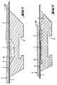
- Figure 1 shows a scraper bar with two wings 3, which are separated by a groove 7.
- water is sucked out of the fiber suspension 2 into the trough 7, which is then pressed back through the sieve 1 and thereby for a swirling of the fibers 12 in the fiber suspension 2 above the screen 1 behind the channel 7.
- the channel 7 thus has a lubricating function at best, but does not contribute to the formation of microturbulence, as is shown in FIG. 2.
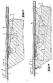
- FIG. 3 shows a foil, the grooves 7 of which have a trapezoidal shape, with a substantial increase in the angle at which the envelope line 13 extends.
- the shorter trapezoidal side faces the wing 3 and runs at a steeper angle with respect to the sieve than the opposite trapezoidal side, which is made longer and which partially removes the water that passes through the sieve 1 through the vacuum that is formed from the drainage surface 4 back through the sieve upwards into the fiber suspension 2 and here leads to the whirling up of the fibers 12 and the pigments 14.
- the arrows 15 indicate the direction of flow of the water. Of course, not all of the water comes back through the sieve 1 into the fiber suspension 2, rather the larger part is removed and flows downwards in the rear region of the drainage surface 4. Another part is stripped from the leading edge 16 of the following foil from the screen 1.
- the distance 8 between the individual channels which is measured from the lowest point of the channel 7 or, in the case of a horizontal version of the channel 7, from the center of the channel bottom to the center of the following channel curve, increases in the direction of sieve travel, and the depth of the channels increases.
- the drainage area 4 is shown in all drawings over its full width 9 as provided with channels 7. However, it is also possible to arrange these channels only in the rear region, that is to say in the region of the drainage surface 4 that is furthest away from the wing 3.
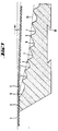
- FIGS. 5 and 6 show a step 10 between the wing 3 and the envelope line 13, which is S-shaped in FIG. 5 and merges directly into the wave trough 6 and from there into the wave crest 5 of the first channel 7.
- This stage 10 creates a free space 11 in the area of the wing 3 between the sleeve line 13 and the screen 1, in which the vacuum created by a vacuum pump or downpipes acts.
- the moldings are equipped with T-grooves 17, dovetail grooves 18, T-rails 19 or dovetail rails 20.
Landscapes
- Paper (AREA)
Abstract
Claims (14)
Priority Applications (1)
| Application Number | Priority Date | Filing Date | Title |
|---|---|---|---|
| AT86902327T ATE47610T1 (de) | 1985-04-13 | 1986-04-11 | Streichleiste fuer eine papiermaschine. |
Applications Claiming Priority (2)
| Application Number | Priority Date | Filing Date | Title |
|---|---|---|---|
| DE3513320 | 1985-04-13 | ||
| DE19853513320 DE3513320A1 (de) | 1985-04-13 | 1985-04-13 | Streichleiste fuer eine papiermaschine |
Publications (2)
| Publication Number | Publication Date |
|---|---|
| EP0256009A1 EP0256009A1 (fr) | 1988-02-24 |
| EP0256009B1 true EP0256009B1 (fr) | 1989-10-25 |
Family
ID=6267963
Family Applications (1)
| Application Number | Title | Priority Date | Filing Date |
|---|---|---|---|
| EP86902327A Expired EP0256009B1 (fr) | 1985-04-13 | 1986-04-11 | Feuille egoutteuse pour machine a papier |
Country Status (6)
| Country | Link |
|---|---|
| US (1) | US4789433A (fr) |
| EP (1) | EP0256009B1 (fr) |
| JP (1) | JPS62502483A (fr) |
| DE (2) | DE3513320A1 (fr) |
| FI (1) | FI85040C (fr) |
| WO (1) | WO1986006117A1 (fr) |
Families Citing this family (20)
| Publication number | Priority date | Publication date | Assignee | Title |
|---|---|---|---|---|
| FI86963C (fi) * | 1989-07-06 | 1992-11-10 | Ahlstroem Oy | Anordning och foerfarande foer behandling av massa |
| US5076894A (en) * | 1990-05-04 | 1991-12-31 | Simmons Holt W | Suction box apparatus with composite cover elements mounted in slots on cross braces |
| JP2749971B2 (ja) * | 1990-07-30 | 1998-05-13 | 三菱重工業株式会社 | 抄紙機の紙層形成装置 |
| US5248392A (en) * | 1990-07-30 | 1993-09-28 | Mitsubishi Jukogyo Kabushiki Kaisha | Sheet-forming apparatus for a twin wire paper machine with positive pulse shoe blades |
| BR9506152A (pt) * | 1994-04-12 | 1996-04-16 | Jwi Ltd | Formação aperfeiçoada em uma máquina de fabricação de papel com dois tecidos de formação |
| US5766420A (en) * | 1994-05-02 | 1998-06-16 | Smurfut Carton Y Papel De Mexico | Under felt inclined flat former to produce multilayer or monolayer sheet of paper |
| US5681430A (en) * | 1995-08-23 | 1997-10-28 | Thermo Fibertek Inc. | Activity induction in papermaking |
| US5830322A (en) * | 1996-02-13 | 1998-11-03 | Thermo Fibertek Inc. | Velocity induced drainage method and unit |
| US5922173A (en) * | 1997-04-22 | 1999-07-13 | Thermo Fibertek Inc. | Paper forming activity control with lifting variable inertial stimulation blades with limited-vent indented-surfaces |
| US5932072A (en) * | 1997-04-22 | 1999-08-03 | Thermo Fibertek Inc. | Paper forming activity blade with mounting buttons |
| US6126786A (en) * | 1998-06-18 | 2000-10-03 | White; James D. | Apparatus and method of generating stock turbulence in a fourdrinier forming section |
| US6372093B1 (en) | 2001-04-26 | 2002-04-16 | Wilbanks International, Inc. | Adjustable foil apparatus for papermaking machine |
| DE10327425A1 (de) * | 2003-06-18 | 2005-01-05 | Voith Paper Patent Gmbh | Doppelsiebformer einer Maschine zur Herstellung einer Faserstoffbahn |
| HUE025276T2 (en) | 2006-02-03 | 2016-02-29 | Y Lopez Caram Luis Fernando Cabrera | Fibreboard making equipment and method for maintaining hydrodynamic processes for producing paper sheets |
| US8163136B2 (en) * | 2010-12-16 | 2012-04-24 | FC Papel LLC | Energy saving papermaking forming apparatus system, and method for lowering consistency of fiber suspension |
| CA2842503A1 (fr) | 2011-07-21 | 2013-01-24 | Fcpapel Llc | Appareil de formation de fabrication de papier a economie d'energie, systeme et procede permettant de reduire la consistance d'une suspension de fibres |
| US9626589B1 (en) | 2015-01-19 | 2017-04-18 | Ricoh Co., Ltd. | Preview image acquisition user interface for linear panoramic image stitching |
| US9594980B1 (en) | 2015-01-19 | 2017-03-14 | Ricoh Co., Ltd. | Image acquisition user interface for linear panoramic image stitching |
| KR101834463B1 (ko) * | 2017-01-17 | 2018-03-05 | 전용경 | 표면 트러블파동을 이용한 지합 개선 제지장치 헤드박스 |
| AT519874B1 (de) * | 2017-08-28 | 2018-11-15 | Klaus Ing Bartelmuss | Abstreifleiste zur Verwendung in einer Anlage zur Herstellung eines Papierbandes, Bausatz und Anlage zur Herstellung eines Papierbandes |
Family Cites Families (12)
| Publication number | Priority date | Publication date | Assignee | Title |
|---|---|---|---|---|
| CA699193A (en) * | 1964-12-01 | John Inglis Co. Limited | Water extracting device for paper machines | |
| US3496064A (en) * | 1966-07-15 | 1970-02-17 | Norton Co | Metal oxide covered bearing structures for papermaking machines |
| DE1761838B1 (de) * | 1968-07-12 | 1972-01-05 | Voith Gmbh J M | Entwaesserungsleiste fuer Langsieb-Papiermaschinen |
| US3573159A (en) * | 1968-08-30 | 1971-03-30 | Anglo Paper Prod Ltd | Deflocculation of pulp stock suspension with pressure pulses |
| GB1447486A (en) * | 1972-07-26 | 1976-08-25 | Jwi Ltd | Blades for papermaking machines |
| US4123322A (en) * | 1977-06-24 | 1978-10-31 | Thermo Electron Corporation | Drainage foil element having two wire bearing portions |
| JPS55103390A (en) * | 1979-02-02 | 1980-08-07 | Toshiba Ceramics Co | Support element for paper making machine |
| DE3274132D1 (en) * | 1981-10-05 | 1986-12-11 | Mk Systems Inc | Method and apparatus for stock deflocculation on the fourdrinier machine wire |
| CA1188142A (fr) * | 1982-01-13 | 1985-06-04 | Henry Johnson | Dispositif pour ameliorer la mise en forme du papier |
| BR8207587A (pt) * | 1982-06-28 | 1984-04-17 | Albany Int Corp | Lamina de pulsacao positiva;processo para precondicionar uma tira umida de material transportador sobr um fio |
| US4420370A (en) * | 1982-07-19 | 1983-12-13 | Jwi Ltd. | Pulp agitating device and method having multiple protruding inserts |
| US4532009A (en) * | 1983-04-01 | 1985-07-30 | Albany International | Forming board elements |
-
1985
- 1985-04-13 DE DE19853513320 patent/DE3513320A1/de not_active Withdrawn
-
1986
- 1986-04-11 DE DE8686902327T patent/DE3666597D1/de not_active Expired
- 1986-04-11 WO PCT/DE1986/000158 patent/WO1986006117A1/fr not_active Ceased
- 1986-04-11 JP JP61502214A patent/JPS62502483A/ja active Pending
- 1986-04-11 US US07/007,909 patent/US4789433A/en not_active Expired - Fee Related
- 1986-04-11 EP EP86902327A patent/EP0256009B1/fr not_active Expired
-
1987
- 1987-09-21 FI FI874118A patent/FI85040C/fi not_active IP Right Cessation
Also Published As
| Publication number | Publication date |
|---|---|
| FI85040B (fi) | 1991-11-15 |
| DE3666597D1 (en) | 1989-11-30 |
| FI874118A0 (fi) | 1987-09-21 |
| US4789433A (en) | 1988-12-06 |
| FI874118L (fi) | 1987-09-21 |
| EP0256009A1 (fr) | 1988-02-24 |
| DE3513320A1 (de) | 1986-10-23 |
| FI85040C (fi) | 1992-02-25 |
| JPS62502483A (ja) | 1987-09-24 |
| WO1986006117A1 (fr) | 1986-10-23 |
Similar Documents
| Publication | Publication Date | Title |
|---|---|---|
| WO1986006117A1 (fr) | Feuille egoutteuse pour machine a papier | |
| DE1761229A1 (de) | Auflaufkasten fuer Papiermaschinen | |
| DE4225297C2 (de) | Stoffauflauf für eine Papiermaschine | |
| EP0486814B1 (fr) | Partie humide pour machine à papier à deux toiles | |
| DE3101407A1 (de) | Stoffauflaufvorrichtung fuer eine papiermaschine | |
| DE19530983B4 (de) | Vorrichtung zum Herstellen eines mehrlagigen Papiers oder Kartons | |
| CH688589A5 (de) | Vorrichtung an einer Karde zum Abnehmen und Zusammenfassen eines aus einem Lieferwerk der Karde austretenden Faserflors. | |
| EP1280959B1 (fr) | Section de formage a deux toiles | |
| DE69810980T2 (de) | Doppelsiebformer in einer Papiermaschine mit einer Entwässerungsvorrichtung | |
| DE3047997C2 (de) | Stoffauflauf für eine Papiermaschine | |
| DE3047998C2 (de) | Stoffauflauf für eine Papiermaschine | |
| AT524266B1 (de) | Entwässerungsvorrichtung | |
| DE69726294T2 (de) | Geneigter unterfilz flachformer zur herstellung von einzel- oder mehrlagigen papieren | |
| WO1992004500A1 (fr) | Ejecteur a fente, notamment pour machines a papier a deux toiles | |
| DE3227189A1 (de) | Egoutteureinrichtung zum entwaessern einer faserstoffbahn auf einer langsiebmaschine | |
| EP4328376B1 (fr) | Formeur à tamis oblique | |
| DE1461179A1 (de) | Siebpartie einer Langsiebpapiermaschine mit Blattbildung unter Luftabschluss | |
| DE9105797U1 (de) | Doppelsiebpartie einer Papier- oder Kartonmaschine | |
| EP1342834A2 (fr) | Procédé et caisse de tête pour une machine de fabrication d' une bande fibreuse | |
| DE2229509A1 (de) | Maschinenteile | |
| DE8715911U1 (de) | Dachgaube mit einem umlaufenden Dachanschlußrand | |
| DE29506380U1 (de) | Formierschuh für den Blattbildungsbereich einer Papier- oder Kartonmaschine | |
| EP1398412A1 (fr) | Procédé et section de formage à deux toiles pour la production d'une bande fibreuse | |
| EP1489225A2 (fr) | Dispositif pour améliorer les propriétés d'une bande de matériau fibreux fabriquée dans une section de formage | |
| DE2210862C3 (de) | Siebpartie einer nach dem Naßverfahren arbeitenden Vlieslegemaschine, insbesondere einer Papiermaschine |
Legal Events
| Date | Code | Title | Description |
|---|---|---|---|
| PUAI | Public reference made under article 153(3) epc to a published international application that has entered the european phase |
Free format text: ORIGINAL CODE: 0009012 |
|
| 17P | Request for examination filed |
Effective date: 19870326 |
|
| AK | Designated contracting states |
Kind code of ref document: A1 Designated state(s): AT BE CH DE FR GB IT LI LU NL SE |
|
| 17Q | First examination report despatched |
Effective date: 19890322 |
|
| ITF | It: translation for a ep patent filed | ||
| GRAA | (expected) grant |
Free format text: ORIGINAL CODE: 0009210 |
|
| AK | Designated contracting states |
Kind code of ref document: B1 Designated state(s): AT BE CH DE FR GB IT LI LU NL SE |
|
| REF | Corresponds to: |
Ref document number: 47610 Country of ref document: AT Date of ref document: 19891115 Kind code of ref document: T |
|
| REF | Corresponds to: |
Ref document number: 3666597 Country of ref document: DE Date of ref document: 19891130 |
|
| ET | Fr: translation filed | ||
| GBT | Gb: translation of ep patent filed (gb section 77(6)(a)/1977) | ||
| PG25 | Lapsed in a contracting state [announced via postgrant information from national office to epo] |
Ref country code: LU Free format text: LAPSE BECAUSE OF NON-PAYMENT OF DUE FEES Effective date: 19900430 |
|
| PLBE | No opposition filed within time limit |
Free format text: ORIGINAL CODE: 0009261 |
|
| STAA | Information on the status of an ep patent application or granted ep patent |
Free format text: STATUS: NO OPPOSITION FILED WITHIN TIME LIMIT |
|
| 26N | No opposition filed | ||
| REG | Reference to a national code |
Ref country code: CH Ref legal event code: PUE Owner name: CERASIV GMBH INNOVATIVES KERAMIK-ENGINEERING Ref country code: CH Ref legal event code: PFA Free format text: STORA FELDMUEHLE AKTIENGESELLSCHAFT |
|
| REG | Reference to a national code |
Ref country code: GB Ref legal event code: 732 |
|
| ITPR | It: changes in ownership of a european patent |
Owner name: CESSIONE;CERASIV GMBH INNOVATIVE KERAMIK - ENGINEE |
|
| REG | Reference to a national code |
Ref country code: FR Ref legal event code: TP Ref country code: FR Ref legal event code: CD Ref country code: FR Ref legal event code: CA |
|
| BECA | Be: change of holder's address |
Free format text: 920604 *CERASIV G.M.B.H. INNOVATIVES KERAMIK-ENGINEERING:MUENCHENWERTHER STRASSE 15, D-4000 DUESSELDORF |
|
| BECH | Be: change of holder |
Free format text: 920604 *CERASIV G.M.B.H. INNOVATIVES KERAMIK-ENGINEERING |
|
| NLT1 | Nl: modifications of names registered in virtue of documents presented to the patent office pursuant to art. 16 a, paragraph 1 |
Owner name: STORA FELDMUEHLE AKTIENGESELLSCHAFT TE DUESSELDORF |
|
| ITTA | It: last paid annual fee | ||
| NLS | Nl: assignments of ep-patents |
Owner name: CERASIV GMBH INNOVATIVES KERAMIK-ENGINEERING TE DU |
|
| EAL | Se: european patent in force in sweden |
Ref document number: 86902327.5 |
|
| PGFP | Annual fee paid to national office [announced via postgrant information from national office to epo] |
Ref country code: GB Payment date: 19980402 Year of fee payment: 13 |
|
| PGFP | Annual fee paid to national office [announced via postgrant information from national office to epo] |
Ref country code: FR Payment date: 19980408 Year of fee payment: 13 |
|
| PGFP | Annual fee paid to national office [announced via postgrant information from national office to epo] |
Ref country code: CH Payment date: 19980427 Year of fee payment: 13 |
|
| PGFP | Annual fee paid to national office [announced via postgrant information from national office to epo] |
Ref country code: AT Payment date: 19980428 Year of fee payment: 13 |
|
| PGFP | Annual fee paid to national office [announced via postgrant information from national office to epo] |
Ref country code: SE Payment date: 19980429 Year of fee payment: 13 |
|
| PGFP | Annual fee paid to national office [announced via postgrant information from national office to epo] |
Ref country code: NL Payment date: 19980430 Year of fee payment: 13 |
|
| PGFP | Annual fee paid to national office [announced via postgrant information from national office to epo] |
Ref country code: BE Payment date: 19980512 Year of fee payment: 13 |
|
| PGFP | Annual fee paid to national office [announced via postgrant information from national office to epo] |
Ref country code: DE Payment date: 19980609 Year of fee payment: 13 |
|
| PG25 | Lapsed in a contracting state [announced via postgrant information from national office to epo] |
Ref country code: GB Free format text: LAPSE BECAUSE OF NON-PAYMENT OF DUE FEES Effective date: 19990411 Ref country code: AT Free format text: LAPSE BECAUSE OF NON-PAYMENT OF DUE FEES Effective date: 19990411 |
|
| PG25 | Lapsed in a contracting state [announced via postgrant information from national office to epo] |
Ref country code: SE Free format text: LAPSE BECAUSE OF NON-PAYMENT OF DUE FEES Effective date: 19990412 |
|
| PG25 | Lapsed in a contracting state [announced via postgrant information from national office to epo] |
Ref country code: LI Free format text: LAPSE BECAUSE OF NON-PAYMENT OF DUE FEES Effective date: 19990430 Ref country code: CH Free format text: LAPSE BECAUSE OF NON-PAYMENT OF DUE FEES Effective date: 19990430 Ref country code: BE Free format text: LAPSE BECAUSE OF NON-PAYMENT OF DUE FEES Effective date: 19990430 |
|
| BERE | Be: lapsed |
Owner name: CERASIV G.M.B.H. INNOVATIVES KERAMIK-ENGINEERING Effective date: 19990430 |
|
| PG25 | Lapsed in a contracting state [announced via postgrant information from national office to epo] |
Ref country code: NL Free format text: LAPSE BECAUSE OF NON-PAYMENT OF DUE FEES Effective date: 19991101 |
|
| GBPC | Gb: european patent ceased through non-payment of renewal fee |
Effective date: 19990411 |
|
| REG | Reference to a national code |
Ref country code: CH Ref legal event code: PL |
|
| PG25 | Lapsed in a contracting state [announced via postgrant information from national office to epo] |
Ref country code: FR Free format text: LAPSE BECAUSE OF NON-PAYMENT OF DUE FEES Effective date: 19991231 |
|
| NLV4 | Nl: lapsed or anulled due to non-payment of the annual fee |
Effective date: 19991101 |
|
| EUG | Se: european patent has lapsed |
Ref document number: 86902327.5 |
|
| REG | Reference to a national code |
Ref country code: FR Ref legal event code: ST |
|
| PG25 | Lapsed in a contracting state [announced via postgrant information from national office to epo] |
Ref country code: DE Free format text: LAPSE BECAUSE OF NON-PAYMENT OF DUE FEES Effective date: 20000201 |
|
| PG25 | Lapsed in a contracting state [announced via postgrant information from national office to epo] |
Ref country code: IT Free format text: LAPSE BECAUSE OF NON-PAYMENT OF DUE FEES;WARNING: LAPSES OF ITALIAN PATENTS WITH EFFECTIVE DATE BEFORE 2007 MAY HAVE OCCURRED AT ANY TIME BEFORE 2007. THE CORRECT EFFECTIVE DATE MAY BE DIFFERENT FROM THE ONE RECORDED. Effective date: 20050411 |