EP0255128A2 - Automatisches photographisches Kopiergerät mit Simulator und Verfahren zum Eichen des Simulators dieses Kopiergerätes - Google Patents
Automatisches photographisches Kopiergerät mit Simulator und Verfahren zum Eichen des Simulators dieses Kopiergerätes Download PDFInfo
- Publication number
- EP0255128A2 EP0255128A2 EP87111012A EP87111012A EP0255128A2 EP 0255128 A2 EP0255128 A2 EP 0255128A2 EP 87111012 A EP87111012 A EP 87111012A EP 87111012 A EP87111012 A EP 87111012A EP 0255128 A2 EP0255128 A2 EP 0255128A2
- Authority
- EP
- European Patent Office
- Prior art keywords
- negative
- adjusting
- imaging device
- simulator
- film
- Prior art date
- Legal status (The legal status is an assumption and is not a legal conclusion. Google has not performed a legal analysis and makes no representation as to the accuracy of the status listed.)
- Granted
Links
Images


Classifications
-
- H—ELECTRICITY
- H04—ELECTRIC COMMUNICATION TECHNIQUE
- H04N—PICTORIAL COMMUNICATION, e.g. TELEVISION
- H04N1/00—Scanning, transmission or reproduction of documents or the like, e.g. facsimile transmission; Details thereof
- H04N1/46—Colour picture communication systems
- H04N1/56—Processing of colour picture signals
- H04N1/60—Colour correction or control
- H04N1/6011—Colour correction or control with simulation on a subsidiary picture reproducer
-
- G—PHYSICS
- G03—PHOTOGRAPHY; CINEMATOGRAPHY; ANALOGOUS TECHNIQUES USING WAVES OTHER THAN OPTICAL WAVES; ELECTROGRAPHY; HOLOGRAPHY
- G03B—APPARATUS OR ARRANGEMENTS FOR TAKING PHOTOGRAPHS OR FOR PROJECTING OR VIEWING THEM; APPARATUS OR ARRANGEMENTS EMPLOYING ANALOGOUS TECHNIQUES USING WAVES OTHER THAN OPTICAL WAVES; ACCESSORIES THEREFOR
- G03B27/00—Photographic printing apparatus
- G03B27/72—Controlling or varying light intensity, spectral composition, or exposure time in photographic printing apparatus
- G03B27/73—Controlling exposure by variation of spectral composition, e.g. multicolor printers
- G03B27/735—Controlling exposure by variation of spectral composition, e.g. multicolor printers in dependence upon automatic analysis of the original
Definitions
- the present invention relates to an automatic photographic printing apparatus with a simulator and a method of adjusting the simulator, and more particularly, to a simulator which is capable of displaying on a CRT display an image which is to be printed on a photographic paper by an automatic photographic color printing apparatus, and an adjusting method therefor.
- Such an automatic photographic color printing apparatus generally comprises a light source, a light adjusting filter, a mirror box, a negative carrier, and an optical system having a black shutter, which are aligned in the apparatus in that order.
- the negative color film supported by the negative carrier is irradiated by the light source, and the black shutter is opened for a predetermined period of time (the exposure time is made constant) so that the image in the negative color film is formed on a sheet of photographic paper.
- the photographic paper on which the image of the color negative has been formed is then automatically developed by a developing process so that it becomes a print copy.
- the light transmitted through the negative is broken down into primary colors including red light (R), green light (G), and blue light (B) by the light receiving element.
- the density of each primary color is controlled using the LATD on the basis of Theorem of Evans, while the slopes of these three primary colors are controlled such that they have the same slope, so as to control the color balance.
- print copies prepared by this automatic photographic printing apparatus have the same density and color balance.
- the major subject in the color negative has the optimum density but the density of its background is higher or lower, this density of the background affects the exposure, resulting in density failure.
- the difference in color balance between the major subject and the background e.g., the complementary relationship between the colors of the major subject and the background, produces color failure. In such a case, density compensation or slope control will not ensure a print copy of excellent quality, and the negative must be printed and developed again.
- Japanese Patent Laid-Open No. 4673l/l978 discloses a photographic inspection device provided with a simulator which is capable of displaying on a TV screen the image in a negative which is reproduced via a TV camera.
- the color video signals are adjusted such that the image displayed on the TV screen has a desired density and color balance, and these adjusted color video signals are employed to print the negative in an automatic photographic printing apparatus.
- the automatic photographic printing apparatus disclosed in the specification of Japanese Patent Publication No. 25220/l967, the image in a negative which is to be printed on the photographic paper is displayed on a TV screen, and the automatic exposure device is coupled to the resistor for adjusting the brightness and contrast of the TV. In either case, the image is simulated so as to reduce the frequency with which a reprinting and redeveloping process has to be resorted to.
- the automatic photographic printing apparatus and the inspection device employ separate light sources.
- the image formed on the photographic paper will not be the same as that displayed on the TV screen due to the use of different light sources and it is difficult to adjust both the light sources of the automatic photographic printing apparatus and the inspection apparatus to the same conditions and maintain the conditions.
- the automatic photographic printing apparatus and the inspection device are independent from each other, after the exposure conditions in the former are determined the latter must be adjusted such that the exposure conditions in the latter coincides with those in the former. Such an adjustment requires much time and it is much difficult to conduct the adjustment accurately, resulting in a deterioration in simulating performance.
- the TV signals are merely controlled such that an image displayed on the TV screen is appropriate even though the coloring characteristics of the TV are different from those of the photographic paper. Therefore, the image which is to be printed cannot be displayed on the TV screen.
- the ⁇ (about 0.6) of the negative is first decreased by the correcting circuit in the camera and is then increased by the ⁇ correcting circuit in the simulator. This leads to degradation of the SN ratio and to deterioration of the quality of the image on the TV.
- two ⁇ correcting circuits are necessary, one in a camera and the other in a simulator, resulting in an increase in production costs.
- the amount of light to be adjusted may exceed the adjustable range of the filter.
- the exposure time is decreased or increased by means of a black shutter.
- the black shutter When the exposure time is controlled by the black shutter, the intensity of light is not changed by the filter, and an image which is to be printed on a photographic paper cannot be displayed when the color negative film is imaged.
- the length of exposure time is determined with the irregularity of reciprocity rule taken into consideration. This makes the image to be printed and to be displayed even more different from each other.
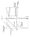
- the camera since the camera has a spectral sensitivity which differs from that of the photographic paper, the overlapping portions of the three primaries in the image reproduced via the camera are not exactly the same as those in the image printed on the photographic paper. Therefore, even after differences in the spectral sensitivities of the camera and the photographic paper have been electrically compensated for, color reproduction or color balance is deteriorated due to this difference in the overlapping portions. More specifically, photographic paper has a low sensitivity to red light, and, in order to compensate for this effect, the light from the light source has the spectral intensity characteristics shown by a curve H in Fig. 9, in which the intensity of red light is large.
- the base portion (the non-exposed portion) of the negative has the absorption characteristics shown by a curve I in Fig. 9, so it absorbs blue and green light to a larger extent.
- the base portion of the negative when the base portion of the negative is irradiated by the light source, the light transmitted through the base portion of the negative has the spectral intensity characteristics shown by a curve J in Fig. 9.
- the base portion of the negative in this state is grey when printed onto the photographic paper. However, the intensity of red light (of wavelengths of about 500 mn to 700 nm) is large, and the peak wavelength of this red light is about 680 nm.
- the imaging device (a single-board camera employing a mosaic filter) has a spectral sensitivity as shown by the spectral sensitivity curve in Fig. l0, in which red and green light, and green and blue light are mixed by a large extent, and the peak wavelength of the red light is about 600 nm.
- the imaging device has a spectral sensitivity as shown by the spectral sensitivity curve in Fig. l0, in which red and green light, and green and blue light are mixed by a large extent, and the peak wavelength of the red light is about 600 nm.
- a primary object of this invention is to provide an automatic photographic printing apparatus with a simulator which is capable of displaying on a display device an image which is to be formed on a print copy.
- a further object of this invention is to provide a method of adjusting a simulator of an automatic photographic printing apparatus which is capable of displaying an image which is to be formed on a print copy even when the exposure time of a shutter is varied.
- a still further object of this invention is to provide at a low production cost a simulator of an automatic photographic printing apparatus which ensures a SN ratio of an excellent value.
- Another object of this invention is to provide a simulator of an automatic photographic printing apparatus which allows the spectral sensitivity of a camera to be approached to that of a photographic paper so as to improve the color reproduction and color balance.
- the present invention provides an automatic photographic printing apparatus including a light source for irradiating rays of light onto a negative color film through a light adjusting filter, an optical system disposed at the side of the negative color film to which rays of light are transmitted through the negative color film for forming the image recorded on the negative color film on a photographic paper, an exposure control device for controlling the light adjusting filter so as to adjust the color balance and density of the image to be formed on the photographic paper, such that the negative color film is automatically printed in such a manner that print copies thereof have the same color balance and density, comprising: an imaging device for imaging the negative color film which has a color balance and a density adjusted by the light adjusting filter from the light transmitted side of the negative color film; and an image information processing unit for converting the output of the imaging device in such a manner that the coloring characteristics of the display device corresponds to those of the photographic paper and displaying it on the display device.
- the light from the light source is irradiated on the photographic paper through the light adjusting filter, negative color film and optical system so as to form the image stored in the negative color film on the photographic paper.
- the exposure device controls the light adjusting filter and thereby adjusts the color balance and density of the image which is to be formed on the photographic paper, so that print copies have the same color balance and density.
- the exposure of the photographic paper is thus performed after the color balance and density of the image have been adjusted.
- the exposed photographic paper is then developed by a developing process to obtain print copies.
- the image device images the negative color film from the light transmitted side thereof, and the image information processing unit converts the signals produced by the imaging device and carrying information on the image which has the adjusted color balance and density, in such a manner that the image displayed on the display device has the same coloring characteristics as those of the photographic paper.
- the thus-converted signals are employed to display the image in the negative on the display device. Since the density and the color balance are adjusted by the exposure control device, the display device can display an image which has the coloring characteristics corresponding to those of the print copy without adjustment of the color balance and density by the image information processing unit, that is, the display device can display an image which is to be formed on a print copy.
- image in the negative color film is displayed on the display device after the color balance and the density thereof have been adjusted. Also, It is displayed on the display device using signals which are converted in such a manner that the image represented by the signals has the coloring characteristics which corresponds to those of the photographic paper. Therefore, an image which is to be formed on a print copy can be displayed on the display device.
- This display makes it possibble for the image which is to be formed on a print copy to be visualized before the development of the exposed photographic paper, and an inappropriate printing and developing can be thereby easily found.
- the density and color balance of the image have been adjusted before the negative film is imaged by the imaging device, accurate measurement with an imaging device having a narrow dynamic range is possible. Functions for adjusting the density or other factors are specially designed. Therefore, they have a simple structure, and the production cost thereof can be thereby reduced.
- the exposure conditions of the automatic exposure control function only in the automatic photographic printing apparatus but it is unnecessary to do that in the simulator.
- the slope control, the correction control, the density control, the light source deviation correcting control and so on conducted in the automatic photographic printing apparatus are also applied in simulator, so that the image can be simulated in a high accuracy.
- the present invention also provides a method of adjusting a simulator provided in an automatic photographic printing apparatus for printing onto photographic paper an image in a negative color film irradiated by light adjusted by an automatic exposure control function, the simulator imaging the negative color film irradiated by the light using an imaging device, the imaging device breaking down received light into three primary colors and outputting electrical signals corresponding to the three primary colors, the simulator converting the output of the imaging device and displaying it as a positive image, comprising the steps of: imaging a reference negative film using the imaging device; and adjusting the gain of the electrical signals so that the output of the imaging device corresponds to the density of the reference negative film.
- the simulator of this invention employs an imaging device which breaks down received light into three primary colors and outputs electrical signals corresponding to these three primary colors. It images the negative color film irradiated by the light from a light source which is adjusted by the automatic exposure control function of the automatic photographic printing apparatus, using this imaging device, then converts the output of the imaging device and displays it as a positive image.
- the output of this imaging device is adjusted first by imaging a standard negative and then by adjusting the electrical signals produced by the imaging device so that the output thereof corresponds to the density of the reference negative.
- a reference negative may be prepared by developing an unexposed film (a so-called transparent negative), or it may be negative (a bull's eye negative) having a portion corresponding to a negative which carries an image of a grey subject as well as a portion corresponding to a negative carrying an image of a yellow green subject, the latter portion surrounding the former portion. More specifically, if a transparent negative is employed as the reference negative, the gain of the electrical signals is adjusted such that the levels of all the electrical signals corresponding to the three primary colors are at the white level (or 90% of the white level).
- the transparent negative has the largest light transmittance of all negatives, and the imaging device receives the maximum amount of light when it images it.
- the arrangement is such that the output of the imaging device has a value corresponding to the white level (the maximum value) when it receives the maximum amount of light.
- the dynamic range of the imaging device can be fully used, if the imaging device has a stop mechanism and the stop mechanism is applied for adjusting brightness. If a normal bull's eye negative is used as the reference negative, it is imaged by the imaging device, and the output of the imaging device is adjusted such that the electrical signal representing each primary color corresponds to the density thereof in the bull's eye negative. When the output of the imaging device is adjusted such that it corresponds to the density of the bull's eye negative, the standard level of the output of the camera is at the grey level. The dynamic range of the imaging device can be thereby fully used if the stop mechanism of the imaging device is utilized.
- the brightness is adjusted by adjusting the stop mechanism of the imaging device if the imaging device has the stop mechanism, but the brightness can be adjusted electrically if the imaging device is not provided with the stop mechanism.
- the standard, or reference, of the brightness can be thereby determined.
- the gain of the electrical signals is adjusted such that the output of the imaging device corresponds to the density of the reference negative. It is therefore possible to set the standard, or reference of the output of the imaging device accurately and automatically.
- the present embodiment is a combination of an automatic photographic color printing apparatus (hereinafter referred to as a printer) and a device (hereinafter referred to as a simulator) for displaying an image in a negative color film in the state wherein it is formed in a print copy prepared by the printer.
- a printer an automatic photographic color printing apparatus
- a simulator a device for displaying an image in a negative color film in the state wherein it is formed in a print copy prepared by the printer.
- a reflecting mirror l2 comprising a cold mirror is disposed behind a light source l0 comprising a halogen lamp.
- a voltage of about 90 % of the rated voltage is supplied to the light source l0 from a power source (not shown) so as to elongate the life thereof and to obtain a predetermined color temperature.
- a light adjusting filter l4 At the light irradiated side of the light source l0 are disposed a light adjusting filter l4 and a mirror box l6 having a scattering board.
- the filter l4 consists of filters of the complementary colors of Y (yellow), M (magenta), and C (cyan).
- each filter a filter plate shaped as a sector of a quadrant which is formed in a logarithmic curve is combined with another filter, and that combination is disposed on right and left sides to make a pair.
- the color balance and amount of the light irradiated from the light source l0 are adjusted by the light adjusting filter l4, and that adjusted light is then diffused uniformly by the mirror box l6 to be irradiated onto a negative color film l8 supported on a negative carrier.
- the filters of the complementary colors in the light adjusting filter are set at the mechanical center, the amount of light is set to a predetermined value (standard, or reference, exposure time) by measuring it by an illuminometer, and the voltage of the light source is set at approximately 90 % of the rated voltage.
- a predetermined value standard, or reference, exposure time
- the voltage of the light source is set at approximately 90 % of the rated voltage.
- On the side of the negative color film l8 which is remote from the light source are disposed an optical system 20 and a black shutter 22 in that order.
- the black shutter 22 is opened for a predetermined time so that the image in the negative color film is formed on a photographic paper 24 and so that the photographic paper is exposed by the light transmitted through the negative color film l8.
- the exposed photographic paper 24 is then developed by a developing process 25 to obtain a print copy 27.
- a driving circuit 26 is connected to the light adjusting filter l4.
- the driving circuit 26 moves the filters of the complementary colors in a direction perpendicular to the optical axis so as to adjust the color balance and the amount of light.
- a driving circuit 29 is connected to the black shutter 22.
- a camera 30 Adjacent to the optical system 20 of the negative color film l8 are disposed a camera 30 constituting an imaging device or an image pick-up device and an image information detecting device 32.
- the camera 30 is constructed by a three-board camera provided with three filters which respectively transmit R (red) light, G (green) light, and B (blue) light as well as a stop mechanism (iris), and which outputs R, G, and B signals.
- the image information detecting device 32 includes a two-dimensional image sensor for detecting image density information on the three primary colors of R, G, and B.
- the two-dimensional image sensor is constructed by a CCD (charge coupled device).
- the camera 30 may be constructed by a CCD single-board camera which is to be described later as a second embodiment.
- the normal print copy has a soft tone with ⁇ of about 2.0, i.e., the ⁇ of the normal photographic paper is set at about 2.0.
- no ⁇ correcting circuit is included in the camera 30, but a single ⁇ correcting circuit which corrects the ⁇ to about l (0.45 ⁇ 2.0) is provided in the simulator.
- the ⁇ of the ⁇ correcting circuit and the value of ⁇ of the CRT together make the ⁇ of the entire system about 2.0.
- the ⁇ characteristics of the CRT and those of the photographic paper are corrected at one time. Because of the use of the single correcting circuit, production costs are reduced. Since the ⁇ is set to about l by the ⁇ correcting circuit, the ⁇ is not substantially changed by the ⁇ correction in the simulator, and the quality of the image on the CRT is thereby increased.
- the camera 30 is connected to a simulator 34 through a gain control circuit 33.
- the image information detecting device 32 is connected to a slope control circuit 63 through a ⁇ , ⁇ correction circuit 38 and a printing system density calculating circuit 40.
- the above-described correction of color balance and density is performed by the printing system density calculating circuit 40 and the slope control circuit 63.
- a chromaticity meter 42 which acts as a measuring device is disposed in such a manner as to face the screen of the CRT 345 constituting one part of the simulator 34 to serve as a display device, and a chromaticity meter 44 faces the print copy 27. Both chromaticity meters 42 and 44 are connected to an I/O port 46 constituting a computer.
- a chromaticity meter may be used for both CRT screen and print copy.
- the computer which acts as a distance operating means and a parameter operating means comprises the I/O port 46, a CPU 48, a read-only-memory (ROM) 50, a random-access-memory (RAM) 52, a digital-analog (D/A) converter 54, analog-digital (A/D) converters 56, 58 and a bus 61 including data buses and control buses which interconnect these components.
- the computer is connected to the gain control circuit 33, the simulator 34, ⁇ , ⁇ correction circuit 38, the slope control circuit 63 which is connected to the printing system density calculating circuit 40, the driving circuit 26, and the driving circuit 29.
- the gain control circuit 33 includes an amplifier 33l, an operational amplifier 332, a flip-flop 333, and resistors 334 to 336.
- a reference voltage (0.7 V which corresponds to the white level) is input to one of the inputs of the operational amplifier 332 through the resistor 336.
- the gain of the camera 30 is adjusted by the gain control circuit 33 as follows: a plurality of standard, or reference, negatives (so called transparent negatives), each having a different negative size, which are obtained by developing non-exposed films, are supported on the negative carrier. Brightness is set to a standard, or reference, value for each negative by adjusting the iris, or the stop mechanism, of the camera. This adjustment of brightness is necessary because the mirror box l6 is converted, the magnification of the optical system 20 is changed, and the amount of light received by the camera 30 is thereby varied by changes in negative size.
- the each transparent negative is imaged by the camera 30, and the gain of the amplifier 33l is adjusted for each negative by delivering analog signals representing camera outputs for the three primary colors, red, green and blue, from the D/A converter 54.
- the output of the amplifier 33l is connected to the operational amplifier 332 which compares the output of the amplifier 33l with the reference voltage.
- the operational amplifier 332 outputs a signal to the flip-flop 333, only when the output of the amplifier 33l corresponds to the reference voltage.
- the output of the camera is set to the white level by stopping the adjustment of the gain when a signal is output by the flip-flop 333.
- the color balance can be adjusted with the output of the camera being set at the white level when the camera images the transparent negative (when the camera receives the maximum amount of light transmitted through the negative).
- the dynamic range of the camera can be thereby fully used, and the standard of the brightness can be easily and accurately determined.
- the gain is adjusted such that the levels of the remaining signals are at the white level. In this way, the iris and the gain can be easily adjusted.
- a standard, or reference, amount of light is obtained by controlling the iris for each negative in the above-described manner, and the gain for each negative is controlled in the above-described manner so that the signals respresenting the red, green and blue primary colors, which are produced by the camera, are at predetermined levels. If a normal negative formed from 35 mm-film has ideal spectral characteristics, the densities of red, green and blue of the negative, excluding the base portion thereof, are respectively 0.26, 0.31 and 0.59.
- the gain is controlled such that the outputs of the camera for red, green and blue are respectively at 0.35 V, 0.3l V and 0.l6 V.
- Each output of the camera thereby corresponds to the density of the negative.
- the gain is controlled such that the levels of the remaining signals are at the predetermined levels. In this way, the iris and the gain can be easily adjusted.
- the position of the camera iris and color balance position (camera output) which are obtained after the gain and the brightness have been adjusted in the above-described manner are digitally stored through channels for each type of negative or for negatives of each size (if the size of the negative is changed, the amount of light is varied by the difference in magnification), so that the iris position and the gain can be automatically switched over by simply switching over the channels when the size of the negative changes.
- the iris position of the camera and the color balance position thereof can be thereby switched over by simply switching over the channels, even if the type or size of the negative color film to be printed on the photographic paper changes.
- the state of the light source shifts from the standard or the reference, that shift must be electrically compensated for. It is therefore preferable for the adjustment to be performed in the state of the light source in which the standard grey in the negative is also the standard, or reference, grey in the print copy.
- the camera 30 is provided with the stop mechanism and is constituted such that the brightness is controlled by adjustment of the stop mechanism.
- the camera 30 which is not provided with the stop mechanism can also be employed.
- the brightness can be adjusted electrically by the adjustment of the gain of the electrical signal.
- the ⁇ , ⁇ correcting circuit includes a signal processing circuit 60 for converting the R signal produced by the image information detecting device 32 into a density signal and for ⁇ , ⁇ correcting that density signal, a signal processing circuit 62 for converting the G signal to a density signal and for ⁇ , ⁇ correcting that density signal, and a signal processing circuit 64 for converting the B signal to a density signal and for ⁇ , ⁇ correcting that density signal. Because the signal processing circuits 60, 62, 64 have the same structure, only the signal processing circuit 60 will be described below.
- the signal processing circuit 60 consists of an off-set correcting circuit 60l, a logarithmic conversion circuit 602 for logarithmically converting the output of the off-set correcting circuit to a density signal, and a ⁇ correcting circuit 603, and a ⁇ correcting circuit 604.
- the off-set correcting circuit 60l includes an operational amplifier OP 3, resistors R6, R7, and a variable power supply Bl.
- the ⁇ correcting circuit 603 includes an operational amplifier OP4, resistors R8, R9, and a variable power source B2, and the ⁇ correcting circuit 604 includes an operational amplifier OP5, resistors Rl0, Rll, and a variable resistor Rl2.
- the ⁇ , ⁇ correcting circuits 603, 604 outputs the corrected R, G and B signals.
- the simulator 34 includes a logarithmic conversion device 34l connected to the output of the gain control circuit 33, a 3 ⁇ 3 matrix (two-dimensional square matrix) circuit 342 for correcting the difference between the density (integral density) viewed with the spectral sensitivity of the camera and that viewed with the spectral sensitivity of the photographic paper, a negative/positive inverting circuit 343 for converting the density of the negative to the analytic density of the photographic paper by the negative/positive inversion, a luminance signal converting circuit 344 for converting the analytic density of the photographic paper to the illuminant luminance of each color of the fluorescent substance of the CRT, and a CRT 345 for coloring the fluorescent substance in accordance with the output of the luminance signal converting circuit 344 so as to display the image imaged by the camera 30.
- These components are connected in series in that order.
- the driving circuit 26 adjusts the color balance and the amount of light by moving each complementary color filter of the light adjusting filer l4 in the vertical direction.
- reciprocity law failure is established, and density is reduced due to the underexposure even though the exposure is appropriate.
- the CPU 48 takes the reciprocity law failure into consideration, and therefore computes the difference between the appropriate exposure and the present exposure and controls the opened time of the black shutter in such a manner that the exposure becomes longer in an amount which is equivalent to that difference.
- the increase in exposure time is then stored in the RAM 52.
- the values obtained by logarithmically converting the B, G and R signals produced from the camera 30 by the logarithmic conversion circuit 34l i.e., the integral densities of the image in the negative color film viewed with the spectral sensitivity of the camera, B ⁇ TV , G ⁇ TV , and R ⁇ TV , are converted into the analytical densities of the negative by using 3 ⁇ 3 matrix A ⁇ 1 (where -l indicates an inverse matrix) as follows:
- the matrix elements, B, ⁇ and A can be obtained beforehand for each standard negative sample with the coloring characteristics of that negative and the spectral sensitivity characteristics of the photographic paper and camera taken into consideration, and is set in the 3 ⁇ 3 matrix circuit 342 which will be described below.
- the pivot point is a point whose density must not be changed at the negative-positive inversion, i.e., a point of the level of the neutral grey (standard grey).
- the black level of the camera is logarithmically transformed into - . That is, when the logarithm of the video signals is taken, the 0 of the black level becomes - . This cannot be displayed on the CRT when negative and positive have been inverted. This means that the black level cannot be inverted to the white level accurately. Accordingly, it is preferable for the negative/positive inversion to be performed with the pivot point set to the neighborhood of 23% of the white level of the camera output V in (0.63, which is the density of the negative excluding its base portion).
- Fig. 4 shows the relationship between the camera output V in and the output V out of the negative/positive inversion circuit 343 at negative/positive inversion with the pivot point set to 23% of the white level of the camera output V in .
- the white level of the camera output is 0.7 V, and 23% of the white level is therefore 0.l6l V.
- y 3.25l8 + logV in ... (7) the coordinates corresponding to 23% of the white level is (0.l6l, 2.47).
- the negative/positive inversion may be performed with the circuit contructed shown in Fig. 5 and with a pivot point obtained in a manner described below.
- the circuit shown in Fig. 5 includes an operational amplifier OPl, an operational amplifier OP2, a variable resistor Rl used to set the reference voltage V x , V y (which corresponds to the pivot point) of the operational amplifiers, and an operation mechanism AC which varies the reference voltage by moving the contact of the variable resistor Rl.
- a signal is input to the inversion input of the operational amplifier OPl through a resistor R2, and a variable resistor R3 is connected between the inversion input of the operational amplifier OPl and its output so as to adjust the gain thereof.
- the output of the operational amplifier OPl is connected to the inversion input of the operational amplifier OP2 through a resistor R4.
- a risistor R5 is connected between the inversion input of the operational amplifier OP2 and its output.
- One of the leads of the variable resistor Rl is grounded, and the other lead thereof is grounded through a power source B.
- the contact of the variable resistor Rl is respectively connected to the non-inversion inputs of the operational amplifiers OPl, OP2.
- the pivot point will be obtained as follows: the negative color film which is colored in standard grey is supported on the negative carrier.
- the negative is imaged by the camera, and is displayed on the screen of the CRT after it has been negative/positive inverted by the circuit shown in Fig. 5.
- a standard grey signal is electrically produced (by setting the output of the CRT at a value which is 23% of the white level of the CRT), and that signal is displayed on the CRT screen adjacent to the image in the above negative.
- the reference voltage, V x , Y y is then varied by changing the resistance of the variable resistor Rl constinuously by the operation of the key board so as to match the image displayed by imaging the negative which is colored in the standard grey and the image reproduced by the electrically produced standard grey signal.
- the pivot point is thereby determined.
- grey level can be set by the sense of an operator. Accordingly, it is possible to set the grey level which is to be provided on a print copy. This enables a very accurate simulation which is not affected by the developing conditions (such as the fatigue of the developer, change in the quality of the developer due to the change in temperature).
- the luminance of the CRT is proportional to the voltage.
- the photographic paper (the print copy) employs absorbing substances (dyes).
- the luminance is not proportional to the amount of dye but the logarithm thereof is proportional to the amount of dye, and as the amount of dye changes, the chromaticity point thereof varies.
- the dyes of the photographic paper are unstable primary colors (cyan, yellow, magenta) having chromaticity points which change in accordance with the amount of dye.
- the luminance signal conversion circuit 344 converts the output D of the negative/positive circuit 343 to the illuminant luminance signal T for each color of the CRT on the basis of the following expression, and outputs the results to the CRT 345.
- T F (log ⁇ 1 (f (D)) ) ... (9) where f is a function to be used when the output D is converted to the integral density, and F a function to be used to transform the integral transmittance log ⁇ 1 ( (D)) to the illuminant luminance signal.
- F, f can be determined by determining the optimum values of the output D and the illuminant luminance signal T beforehand and by performing the optimization by the method of least squares or regression.
- a 3 ⁇ 3 matrix is generally employed to obtain the functions F, f.
- the CRT is controlled by the luminance signals obtained in the above-described manner by the luminance signal conversion circuit 344, so that it displays the images having coloring characteristics which correspond to those of the photographic paper (print copy).
- change in the exposure time is corrected by controlling the gain of the camera, However, it may be adjusted by correcting the elements of the matrix set in the 3 ⁇ 3 matrix circuit.
- the parameters which are set in the 3 ⁇ 3 matrix circuit 342 and luminance signal conversion circuit 344 are determined as follows:
- the standard negative of color chart consisting of a plurality of standard colors (hereinafter referred to as a Macbeth negative) is imaged by the camera, and the data obtained by logarithmically transforming the camera output of each block of the Macbeth negative is input.
- the spectral density of each block of the Macbeth negative is measured, and the printing density of a print copy is calculated to obtain theoretical values using the measured spectral density and spectral sensitivity of the photographic paper. Optimization is then performed by the CPU 48 by the method of least squares, such that the data representing each block of the Macbeth negative matches the theoretical values.
- the number of samples of particular colors e.g., skin color, grey and other colors
- Weighting may be performed on these samples, and the data on these samples are made coincide with the theoretical values.
- the tristimulus values of the CRT, X ⁇ , Y ⁇ , Z ⁇ are related to the electrical signals (theoretical values), T R ⁇ , T G ⁇ , T B ⁇ , which are to be supplied to the CRT as follows:
- the electrical signals to be supplied to the CRT are obtained using Expressions (l0), (ll) as follows: in the expression (l2) is equal to the tristimulus values of the photographic paper in accordance with Expression (l0), and is therefore obtained by measuring the chromaticity points of the print copy 27 using the chromaticity meter 44.
- the electrical signals which are to be supplied to the CRT i.e., the theoretical values, can be thereby determined from Expression (l2).
- the values of the elements of the 3 ⁇ 3 matrix circuit 342 which are determined in the above-described manner are multiplied by - ⁇ to obtain the output D of the negative/positive circuit 343 (the input of the luminance signal conversion circuit 344).
- This D is optimized by the method of least squares or regression using the theoretical values (T ⁇ R , T ⁇ G , T ⁇ B ) on the basis of Expression (9) to determine the parameters of the functions, F, f.
- particular colors e.g., skin color and grey
- the signals representing these colors are made to agree with the theoretical values.
- the differences in the chromaticity point and lightness are expressed quantitatively by the geometrical distances between the points corresponding to the respective standard colors in the print copy and the points corresponding to the respective standard colors on the CRT in the L* a* b* color space.
- the differences in the hue, saturation, and lightness are minimized.
- the parameters may also be determined such that the sum of the differences in the hue and lightness only, or the hue and saturation only, or the lightness and saturation only of respective colors, or again the sum of differences in only one of the three color properties of respective colors, are minimized.
- the parameters may be determined such that the sum of distances of the chromaticity points of the respective standard colors of the images in the standard print copy and in the simulator in the chromaticity diagram are minimized and that the differences in hue and saturation of the images on the CRT and in the print copy are minimized.
- the differences in chromaticity point are expressed quantitatively by the geometrical distances between the points corresponding to the respective standard colors in the print copy and the points corresponding to the respective standard colors on the CRT in the chromaticity diagram.
- the parameters may be determined such that the differences in the lightness of the respective colors which are shown in the coordinates perpendicular to the chromaticity diagram are also minimized.
- Two chromaticity meters are employed in the above example. However, only one chromaticity meter may be switched over for measurement.
- FIG. 6 a second embodiment of this invention will be described in which a single-board camera is employed.
- the same reference numerals are used to denote members or parts which are included in the first embodiment shown in Fig. l, and description thereof is omitted.
- a camera 3l comprising a single-board camera which has a color filter array for breaking down the received light into three primaries, R (red) light, G (green) light, and B (blue) light, as well as a stop mechanism (iris), and which outputs the R, G and B signals in time sharing.
- the image information detecting device 32 including a two-dimensional image sensor for detecting the image density information on the R, G, and B primaries.
- the two-dimensional image sensor is constructed by a CCD (charge coupled device).
- the single-board camera 3l includes: a color filter array including a solid-state image sensor and a mosaic filter in which tiny filters of the three primaries R, G, and B are disposed on the solid-state image sensor in a mosaic form, or a solid-state image sensor and a stripe filter; a crystal filter for preventing Moire; an infrared ray preventing filter; and a filter 3lA which constitutes the present invention, these filters being laminated in that order.
- the single-board camera outputs R, G, and B signals in time sharing in response to the clock.
- Fig. 7 shows the absorption characteristics of the filter 3lA employed in this invention. As will be clear from Fig.
- the filter absorbs light having a wavelength of about 500 nm or 600 nm to a great extent. It also shows a transmittance of l0 % or less with respect to light having a wavelength between 580 nm and 630 nm.
- Fig. 8 shows the spectral characteristics of a single-board camera with this filter mounted thereon, i.e., the relative output thereof in terms of wavelength (the spectral output of the camera including the light source). As can be seen in Fig. 8, the peak wavelength of the red light R is approximately 660 nm, and deviates toward the longer wavelength relative to the red light R in the case of the single-board camera shown in Fig. l0 which is not provided with the filter 3lA.
- the peak wavelength of the red light R in the case of the single-board camera with the filter substantially matches the peak wavelength of the R obtained by coloring the cyan coloring material in the negative - light source system, which is shown by the curve J in Fig. 9.
- the color formed by coloring the cyan coloring material can be thereby detected accurately.
- the filter absorbs light having a wavelength of about 500 nm or about 600 nm to a great extent and has a transmittance of l0 % or less with respect to light having a wavelength between 580 nm and 630 nm, the red light R and the green light G are not mixed to any substantial extent.
- the degree of mixture of green light G and blue light B is also decreased compared with the case of the single-board camera shown in Fig. l0.
- the intensities of the red light R and the green light G are substantially the same. Although the intensity of the blue light B is smaller, it is originally small, as can be seen in Fig. 9, and practically no problem is caused.
- the characteristic curve shown in Fig. 7 is first obtained such that the chromaticity of the positive image which is obtained by displaying the image in the negative color film by the simulator is close to the chromaticity of the image in the print copy prepared from this negative color film by the automatic photographic printing apparatus, and the amounts of the dyes of respective colors, R, G, and B are then adjusted so that they show the characteristics shown by the characteristic curve.
- the camera 3l is provided with a position detector 3lB constructed by a potentiometer for detecting the position of the iris.
- the potentiometer 3lB is connected to the computer.
Landscapes
- Physics & Mathematics (AREA)
- Spectroscopy & Molecular Physics (AREA)
- General Physics & Mathematics (AREA)
- Engineering & Computer Science (AREA)
- Multimedia (AREA)
- Signal Processing (AREA)
- Control Of Exposure In Printing And Copying (AREA)
Applications Claiming Priority (20)
| Application Number | Priority Date | Filing Date | Title |
|---|---|---|---|
| JP17829386A JPH061340B2 (ja) | 1986-07-29 | 1986-07-29 | 自動写真焼付装置 |
| JP178293/86 | 1986-07-29 | ||
| JP18488686 | 1986-08-06 | ||
| JP184886/86 | 1986-08-06 | ||
| JP18488486A JPS6340128A (ja) | 1986-08-06 | 1986-08-06 | シミユレ−タのγ補正方法 |
| JP184884/86 | 1986-08-06 | ||
| JP193048/86 | 1986-08-19 | ||
| JP19304886A JPS6348541A (ja) | 1986-08-19 | 1986-08-19 | 自動写真焼付現像装置用シミユレ−タ |
| JP61217643A JP2724140B2 (ja) | 1986-09-16 | 1986-09-16 | 自動写真焼付装置用シミユレータの画像補正方法 |
| JP217643/86 | 1986-09-16 | ||
| JP21869386 | 1986-09-17 | ||
| JP218693/86 | 1986-09-17 | ||
| JP227378/86 | 1986-09-26 | ||
| JP61227378A JPH061342B2 (ja) | 1986-09-26 | 1986-09-26 | 自動写真焼付装置のシミユレ−タ |
| JP245090/86 | 1986-10-15 | ||
| JP24509086A JPS6398649A (ja) | 1986-10-15 | 1986-10-15 | 自動写真焼付装置用シミユレ−タのパラメ−タ決定方法 |
| JP281536/86 | 1986-11-26 | ||
| JP28153686A JPS63133141A (ja) | 1986-11-26 | 1986-11-26 | シミユレ−タのパラメ−タ決定装置を備えた自動写真焼付装置 |
| JP62152161A JPH0786654B2 (ja) | 1986-08-06 | 1987-06-18 | シミュレ−タ用撮像装置の調整方法 |
| JP152161/87 | 1987-06-18 |
Publications (3)
| Publication Number | Publication Date |
|---|---|
| EP0255128A2 true EP0255128A2 (de) | 1988-02-03 |
| EP0255128A3 EP0255128A3 (en) | 1989-05-10 |
| EP0255128B1 EP0255128B1 (de) | 1993-12-08 |
Family
ID=27580330
Family Applications (1)
| Application Number | Title | Priority Date | Filing Date |
|---|---|---|---|
| EP87111012A Expired - Lifetime EP0255128B1 (de) | 1986-07-29 | 1987-07-29 | Automatisches photographisches Kopiergerät mit Simulator und Verfahren zum Eichen des Simulators dieses Kopiergerätes |
Country Status (3)
| Country | Link |
|---|---|
| US (1) | US4812879A (de) |
| EP (1) | EP0255128B1 (de) |
| DE (1) | DE3788377T2 (de) |
Cited By (3)
| Publication number | Priority date | Publication date | Assignee | Title |
|---|---|---|---|---|
| EP0632317A3 (de) * | 1993-05-28 | 1995-07-19 | Noritsu Koki Co Ltd | Bildkopiergerät. |
| EP0629906A3 (de) * | 1993-06-15 | 1995-07-26 | Noritsu Koki Co Ltd | Uberwachungssystem für einen Bilddrucker. |
| EP0629907A3 (de) * | 1993-06-15 | 1995-08-02 | Noritsu Koki Co Ltd | Fotografische Belichtungsvorrichtung. |
Families Citing this family (32)
| Publication number | Priority date | Publication date | Assignee | Title |
|---|---|---|---|---|
| EP0255127B1 (de) * | 1986-07-29 | 1993-10-06 | Fuji Photo Film Co., Ltd. | Simulator für automatisches fotografisches Kopiergerät |
| US4958220A (en) * | 1988-12-27 | 1990-09-18 | Eastman Kodak Company | Color imaging apparatus producing visually matched displays of perceptually distinct reproduced images |
| US4979032A (en) * | 1988-12-27 | 1990-12-18 | Eastman Kodak Company | Color imaging apparatus producing on various image receptive materials a visually matched hard copy reproduction of a video image displayed |
| US5049984A (en) * | 1989-09-12 | 1991-09-17 | Eastman Kodak Company | Motion picture telecine balanced for negative scanning |
| GB9023013D0 (en) * | 1990-10-23 | 1990-12-05 | Crosfield Electronics Ltd | Method and apparatus for generating representation of an image |
| US5081529A (en) * | 1990-12-18 | 1992-01-14 | Eastman Kodak Company | Color and tone scale calibration system for a printer using electronically-generated input images |
| US5237402A (en) * | 1991-07-30 | 1993-08-17 | Polaroid Corporation | Digital image processing circuitry |
| US5739928A (en) * | 1991-09-12 | 1998-04-14 | Eastman Kodak Company | Technique particularly suited for use in a print preview function for adapting CRT colorimetry to ambient lighting conditions |
| US5218402A (en) * | 1991-09-17 | 1993-06-08 | Eastman Kodak Company | Color image reproduction with compensating light source |
| US5309257A (en) * | 1991-12-31 | 1994-05-03 | Eastman Kodak Company | Method and apparatus for providing color matching between color output devices |
| US5408342A (en) * | 1993-02-25 | 1995-04-18 | Canon Kabushiki Kaisha | Color image processing apparatus, method, and printer driver |
| US5323018A (en) * | 1992-11-23 | 1994-06-21 | Eastman Kodak Company | Storage phosphur size compensation system |
| US5488492A (en) * | 1993-06-04 | 1996-01-30 | Asahi Kogaku Kogyo Kabushiki Kaisha | Apparatus for adjusting color tone of image to be recorded |
| JP2610386B2 (ja) * | 1993-09-28 | 1997-05-14 | 株式会社ハドソン | モニター装置付カメラ |
| US5551011A (en) * | 1994-01-27 | 1996-08-27 | Huyck Licensco, Inc. | Computerized system for simulating paper sheet formation and the appearance of print thereon |
| US5483259A (en) * | 1994-04-12 | 1996-01-09 | Digital Light & Color Inc. | Color calibration of display devices |
| US5576794A (en) * | 1994-05-12 | 1996-11-19 | Eastman Kodak Company | Random batch photofinishing |
| US8261993B2 (en) | 1994-05-25 | 2012-09-11 | Marshall Feature Recognition, Llc | Method and apparatus for accessing electronic data via a familiar printed medium |
| US7703683B2 (en) | 1994-05-25 | 2010-04-27 | Marshall Feature Recognition, Llc | Method and apparatus for accessing electronic data via a familiar printed medium |
| US6164534A (en) * | 1996-04-04 | 2000-12-26 | Rathus; Spencer A. | Method and apparatus for accessing electronic data via a familiar printed medium |
| US7717344B2 (en) * | 1994-05-25 | 2010-05-18 | Marshall Feature Recognition, Llc | Method and apparatus for accessing electronic data via a familiar printed medium |
| US8910876B2 (en) | 1994-05-25 | 2014-12-16 | Marshall Feature Recognition, Llc | Method and apparatus for accessing electronic data via a familiar printed medium |
| US6866196B1 (en) * | 1994-05-25 | 2005-03-15 | Spencer A. Rathus | Method and apparatus for accessing electronic data via a familiar printed medium |
| US7712668B2 (en) * | 1994-05-25 | 2010-05-11 | Marshall Feature Recognition, Llc | Method and apparatus for accessing electronic data via a familiar printed medium |
| US5694484A (en) * | 1995-05-15 | 1997-12-02 | Polaroid Corporation | System and method for automatically processing image data to provide images of optimal perceptual quality |
| US6141080A (en) * | 1995-07-12 | 2000-10-31 | Fuji Photo Film Co., Ltd. | Control negative for use in setting up exposure condition of photo-printer |
| DE19539730C1 (de) * | 1995-10-25 | 1996-10-24 | Agfa Gevaert Ag | Verfahren und Vorrichtung zur Farbabstimmung einer Farb-Videokamera |
| US5818453A (en) * | 1996-01-05 | 1998-10-06 | Weavexx Corporation | System for evaluating print quality for a sheet |
| US6278533B1 (en) | 1996-11-29 | 2001-08-21 | Fuji Photo Film Co., Ltd. | Method of processing image signal |
| US6069981A (en) * | 1997-06-16 | 2000-05-30 | Dainippon Screen Mfg. Co., Ltd. | Image conversion method and record medium |
| JP4255526B2 (ja) * | 1997-11-06 | 2009-04-15 | ソニー株式会社 | 画像処理装置および方法、並びに伝送媒体 |
| EP1030214A3 (de) * | 1999-01-29 | 2003-04-16 | Imip Llc | Verfahren zum Optimieren der Beleuchtungsverteilung in einem photographischen Kopiergerät |
Citations (6)
| Publication number | Priority date | Publication date | Assignee | Title |
|---|---|---|---|---|
| US2981791A (en) * | 1957-03-25 | 1961-04-25 | Technicolor Corp | Printing timer for making color positives on film |
| US3417196A (en) * | 1966-02-17 | 1968-12-17 | Photo Electronics Corp | Electronic color viewer and print timer |
| US3800071A (en) * | 1972-04-10 | 1974-03-26 | Hazeltine Corp | Graphic arts process simultation system |
| EP0054848A1 (de) * | 1980-12-19 | 1982-06-30 | Fotomec - San Marco S.p.A. | Verfahren und Vorrichtung zum Belichten von Aufzeichnungsmaterial bei der Herstellung photographischer Farbkopien |
| EP0173032A2 (de) * | 1984-08-28 | 1986-03-05 | Polaroid Corporation | Digitale Farbbildtransformation |
| US4583186A (en) * | 1984-03-26 | 1986-04-15 | Bremson Data Systems | Computerized video imaging system |
Family Cites Families (2)
| Publication number | Priority date | Publication date | Assignee | Title |
|---|---|---|---|---|
| US4310848A (en) * | 1979-10-18 | 1982-01-12 | Carter Equipment Co., Inc. | Colorimetric evaluation of photographic film |
| JPS5662243A (en) * | 1979-10-25 | 1981-05-28 | Fuji Photo Film Co Ltd | Color film checking device |
-
1987
- 1987-07-29 US US07/079,069 patent/US4812879A/en not_active Expired - Lifetime
- 1987-07-29 DE DE87111012T patent/DE3788377T2/de not_active Expired - Lifetime
- 1987-07-29 EP EP87111012A patent/EP0255128B1/de not_active Expired - Lifetime
Patent Citations (6)
| Publication number | Priority date | Publication date | Assignee | Title |
|---|---|---|---|---|
| US2981791A (en) * | 1957-03-25 | 1961-04-25 | Technicolor Corp | Printing timer for making color positives on film |
| US3417196A (en) * | 1966-02-17 | 1968-12-17 | Photo Electronics Corp | Electronic color viewer and print timer |
| US3800071A (en) * | 1972-04-10 | 1974-03-26 | Hazeltine Corp | Graphic arts process simultation system |
| EP0054848A1 (de) * | 1980-12-19 | 1982-06-30 | Fotomec - San Marco S.p.A. | Verfahren und Vorrichtung zum Belichten von Aufzeichnungsmaterial bei der Herstellung photographischer Farbkopien |
| US4583186A (en) * | 1984-03-26 | 1986-04-15 | Bremson Data Systems | Computerized video imaging system |
| EP0173032A2 (de) * | 1984-08-28 | 1986-03-05 | Polaroid Corporation | Digitale Farbbildtransformation |
Non-Patent Citations (1)
| Title |
|---|
| CHAMBERS-SCIENCE AND TECHNOLOGY DICTIONARY, NEW YORK 1988, page 377 * |
Cited By (3)
| Publication number | Priority date | Publication date | Assignee | Title |
|---|---|---|---|---|
| EP0632317A3 (de) * | 1993-05-28 | 1995-07-19 | Noritsu Koki Co Ltd | Bildkopiergerät. |
| EP0629906A3 (de) * | 1993-06-15 | 1995-07-26 | Noritsu Koki Co Ltd | Uberwachungssystem für einen Bilddrucker. |
| EP0629907A3 (de) * | 1993-06-15 | 1995-08-02 | Noritsu Koki Co Ltd | Fotografische Belichtungsvorrichtung. |
Also Published As
| Publication number | Publication date |
|---|---|
| EP0255128B1 (de) | 1993-12-08 |
| DE3788377T2 (de) | 1994-03-24 |
| US4812879A (en) | 1989-03-14 |
| EP0255128A3 (en) | 1989-05-10 |
| DE3788377D1 (de) | 1994-01-20 |
Similar Documents
| Publication | Publication Date | Title |
|---|---|---|
| EP0255128B1 (de) | Automatisches photographisches Kopiergerät mit Simulator und Verfahren zum Eichen des Simulators dieses Kopiergerätes | |
| US5122831A (en) | Photographic printer | |
| EP0255127B1 (de) | Simulator für automatisches fotografisches Kopiergerät | |
| JPH10221792A (ja) | 写真仕上げシステムのキャリブレーションを行う方法およびその方法に使用する装置 | |
| EP0390172B1 (de) | Belichtungssteuerungsmethode eines fotografischen Kopiergeräts | |
| US3800070A (en) | Device for determining the quantities of colored printing light for the photographic printing of color transparencies | |
| US4866475A (en) | Simulator for automatic photographic printers | |
| US5053807A (en) | Method of producing color image in color photographic print enlarger and device therefor | |
| US4149799A (en) | Photographic printer with automatic slope compensation | |
| US4678319A (en) | Measuring device for selecting the filter in photographic enlarging or copying apparatuses | |
| US4682883A (en) | Photographic color enlarging or copying apparatus | |
| US5671041A (en) | Exposure control method and apparatus for photographic printer | |
| JPH061340B2 (ja) | 自動写真焼付装置 | |
| JPS6340129A (ja) | 画像反転方法 | |
| Loughlin et al. | An instantaneous electronic color-film analyzer | |
| JP2724140B2 (ja) | 自動写真焼付装置用シミユレータの画像補正方法 | |
| JPS6340128A (ja) | シミユレ−タのγ補正方法 | |
| JPS6398649A (ja) | 自動写真焼付装置用シミユレ−タのパラメ−タ決定方法 | |
| JPS6382183A (ja) | 自動写真焼付装置のシミユレ−タ | |
| JP2502131B2 (ja) | 写真焼付露光量の決定方法 | |
| JPH0786654B2 (ja) | シミュレ−タ用撮像装置の調整方法 | |
| JPS6394233A (ja) | 自動写真焼付装置用シミユレ−タの画像反転方法 | |
| JP2719034B2 (ja) | 写真プリンタ | |
| JPH0786655B2 (ja) | シミュレ−タ用撮像装置の調整方法 | |
| JPH07104565B2 (ja) | 自動写真焼付装置のシミユレ−タ |
Legal Events
| Date | Code | Title | Description |
|---|---|---|---|
| PUAI | Public reference made under article 153(3) epc to a published international application that has entered the european phase |
Free format text: ORIGINAL CODE: 0009012 |
|
| AK | Designated contracting states |
Kind code of ref document: A2 Designated state(s): DE FR GB |
|
| PUAL | Search report despatched |
Free format text: ORIGINAL CODE: 0009013 |
|
| AK | Designated contracting states |
Kind code of ref document: A3 Designated state(s): DE FR GB |
|
| 17P | Request for examination filed |
Effective date: 19890921 |
|
| 17Q | First examination report despatched |
Effective date: 19910819 |
|
| GRAA | (expected) grant |
Free format text: ORIGINAL CODE: 0009210 |
|
| AK | Designated contracting states |
Kind code of ref document: B1 Designated state(s): DE FR GB |
|
| REF | Corresponds to: |
Ref document number: 3788377 Country of ref document: DE Date of ref document: 19940120 |
|
| ET | Fr: translation filed | ||
| PLBE | No opposition filed within time limit |
Free format text: ORIGINAL CODE: 0009261 |
|
| STAA | Information on the status of an ep patent application or granted ep patent |
Free format text: STATUS: NO OPPOSITION FILED WITHIN TIME LIMIT |
|
| 26N | No opposition filed | ||
| REG | Reference to a national code |
Ref country code: GB Ref legal event code: IF02 |
|
| PGFP | Annual fee paid to national office [announced via postgrant information from national office to epo] |
Ref country code: FR Payment date: 20060531 Year of fee payment: 20 |
|
| PGFP | Annual fee paid to national office [announced via postgrant information from national office to epo] |
Ref country code: GB Payment date: 20060725 Year of fee payment: 20 |
|
| PGFP | Annual fee paid to national office [announced via postgrant information from national office to epo] |
Ref country code: DE Payment date: 20060830 Year of fee payment: 20 |
|
| REG | Reference to a national code |
Ref country code: GB Ref legal event code: 732E |
|
| REG | Reference to a national code |
Ref country code: GB Ref legal event code: PE20 |
|
| REG | Reference to a national code |
Ref country code: FR Ref legal event code: TP Ref country code: FR Ref legal event code: CD |
|
| PG25 | Lapsed in a contracting state [announced via postgrant information from national office to epo] |
Ref country code: GB Free format text: LAPSE BECAUSE OF EXPIRATION OF PROTECTION Effective date: 20070728 |