EP0253224A2 - Disposition de circuit pour la mise en oeuvre de lampes à décharge basse-pression - Google Patents
Disposition de circuit pour la mise en oeuvre de lampes à décharge basse-pression Download PDFInfo
- Publication number
- EP0253224A2 EP0253224A2 EP87109551A EP87109551A EP0253224A2 EP 0253224 A2 EP0253224 A2 EP 0253224A2 EP 87109551 A EP87109551 A EP 87109551A EP 87109551 A EP87109551 A EP 87109551A EP 0253224 A2 EP0253224 A2 EP 0253224A2
- Authority
- EP
- European Patent Office
- Prior art keywords
- center tap
- capacitor
- diodes
- transistors
- circuit
- Prior art date
- Legal status (The legal status is an assumption and is not a legal conclusion. Google has not performed a legal analysis and makes no representation as to the accuracy of the status listed.)
- Granted
Links
Images

Classifications
-
- H—ELECTRICITY
- H05—ELECTRIC TECHNIQUES NOT OTHERWISE PROVIDED FOR
- H05B—ELECTRIC HEATING; ELECTRIC LIGHT SOURCES NOT OTHERWISE PROVIDED FOR; CIRCUIT ARRANGEMENTS FOR ELECTRIC LIGHT SOURCES, IN GENERAL
- H05B41/00—Circuit arrangements or apparatus for igniting or operating discharge lamps
- H05B41/14—Circuit arrangements
- H05B41/26—Circuit arrangements in which the lamp is fed by power derived from dc by means of a converter, e.g. by high-voltage dc
- H05B41/28—Circuit arrangements in which the lamp is fed by power derived from dc by means of a converter, e.g. by high-voltage dc using static converters
-
- H—ELECTRICITY
- H02—GENERATION; CONVERSION OR DISTRIBUTION OF ELECTRIC POWER
- H02M—APPARATUS FOR CONVERSION BETWEEN AC AND AC, BETWEEN AC AND DC, OR BETWEEN DC AND DC, AND FOR USE WITH MAINS OR SIMILAR POWER SUPPLY SYSTEMS; CONVERSION OF DC OR AC INPUT POWER INTO SURGE OUTPUT POWER; CONTROL OR REGULATION THEREOF
- H02M1/00—Details of apparatus for conversion
- H02M1/42—Circuits or arrangements for compensating for or adjusting power factor in converters or inverters
- H02M1/4208—Arrangements for improving power factor of AC input
- H02M1/4275—Arrangements for improving power factor of AC input by adding an auxiliary output voltage in series to the input
-
- Y—GENERAL TAGGING OF NEW TECHNOLOGICAL DEVELOPMENTS; GENERAL TAGGING OF CROSS-SECTIONAL TECHNOLOGIES SPANNING OVER SEVERAL SECTIONS OF THE IPC; TECHNICAL SUBJECTS COVERED BY FORMER USPC CROSS-REFERENCE ART COLLECTIONS [XRACs] AND DIGESTS
- Y02—TECHNOLOGIES OR APPLICATIONS FOR MITIGATION OR ADAPTATION AGAINST CLIMATE CHANGE
- Y02B—CLIMATE CHANGE MITIGATION TECHNOLOGIES RELATED TO BUILDINGS, e.g. HOUSING, HOUSE APPLIANCES OR RELATED END-USER APPLICATIONS
- Y02B70/00—Technologies for an efficient end-user side electric power management and consumption
- Y02B70/10—Technologies improving the efficiency by using switched-mode power supplies [SMPS], i.e. efficient power electronics conversion e.g. power factor correction or reduction of losses in power supplies or efficient standby modes
-
- Y—GENERAL TAGGING OF NEW TECHNOLOGICAL DEVELOPMENTS; GENERAL TAGGING OF CROSS-SECTIONAL TECHNOLOGIES SPANNING OVER SEVERAL SECTIONS OF THE IPC; TECHNICAL SUBJECTS COVERED BY FORMER USPC CROSS-REFERENCE ART COLLECTIONS [XRACs] AND DIGESTS
- Y10—TECHNICAL SUBJECTS COVERED BY FORMER USPC
- Y10S—TECHNICAL SUBJECTS COVERED BY FORMER USPC CROSS-REFERENCE ART COLLECTIONS [XRACs] AND DIGESTS
- Y10S315/00—Electric lamp and discharge devices: systems
- Y10S315/05—Starting and operating circuit for fluorescent lamp
Definitions
- the invention relates to a circuit arrangement for high-frequency operation of one or more low-pressure discharge lamps connected in parallel with one another, the circuit having the following features: - A mains rectifier with a backup capacitor connected in parallel to the DC output - A push-pull frequency generator connected to the direct current output of the mains rectifier with two alternating switching transistors and a control circuit, a center tap being provided between the two transistors - A series resonance circuit associated with each low-pressure discharge lamp, consisting of resonance inductance, coupling capacitor and resonance capacitance - Connection lines for the low-pressure discharge lamps, one line connecting the first electrodes of the lamps via the resonance inductances with the center tap between the two transistors and a further line connecting the second electrodes of the lamps with the plus and / or minus pole of the mains rectifier - A smoothing capacitor in parallel with the switching stretch the two transistors of the push-pull frequency generator - And a harmonic filter, consisting of a series connection of two diodes and two or more capacitors, the series connection of
- the circuit arrangement can also be used to operate a plurality of lamps connected in series in the same way.
- the first electrode of the first lamp is connected to the center tap between the two transistors via the resonance inductance and the second electrode of the last lamp is connected to the positive and / or negative pole of the mains rectifier.
- the harmonic filter circuit additionally has an iron choke in the line frequency part of the circuit arrangement in order to smooth the remaining charging peaks in the current flow taken up by the network in such a way that the final current form fulfills the existing regulations.
- the iron choke has significantly larger dimensions than those otherwise used in the circuit arrangement Components.
- the circuit arrangement can thus not be accommodated in the smallest of spaces, which makes it impossible, for example, to integrate the circuit into the base of a low-pressure discharge lamp.
- the aim of the invention is to provide a circuit arrangement for operating low-pressure discharge lamps which contains a harmonic filter circuit with which an iron choke can be dispensed with.
- the circuit elements required for the harmonic filter should have the smallest possible dimensions.
- the circuit arrangement should enable optimal filtering of the harmonic content with the new circuit parts.
- the circuit arrangement for high-frequency operation of one or more low-pressure discharge lamps connected in parallel with one another with the features listed in the preamble of the main claim is characterized in that two further diodes are connected in series as a harmonic filter in parallel with the series connection of the two diodes in the forward DC direction, the center tap between the two further diodes is connected via a capacitor to the center tap between the two transistors of the counter clock frequency generator.
- the additional circuit elements create a "double pump system” that continuously feeds energy back into the smoothing capacitor.
- the harmonic filter thus ensures a sinusoidal mains current consumption and a linear dependence of the lamp power on the mains voltage.
- C Res (P Ges ⁇ ⁇ 2 ⁇ 109) / (U N 2 ⁇ f B ) Do not exceed the calculated maximum value.
- P Ges is the total power consumed by the lamp (s) plus the circuit arrangement in W, U N the nominal mains voltage in V for the system and f B the lamp operating frequency in Hz. If the maximum value specified for the entire pump capacity is exceeded, then Switching losses occur because the capacitance stored in the capacitors cannot flow completely into the smoothing capacitor during the break times of the switching transistors. In addition, the transistors are loaded with short-circuit currents and can be destroyed.
- the capacitor which connects the center tap between the two further diodes to the center tap between the two transistors of the push-pull frequency generator must have a capacitance which is 0.1 to 0.4 times the sum of the capacitances of the capacitors of the harmonic filter. This restriction is necessary due to the quadratic change in energy in the course of the sinusoidal mains voltage half-wave. If the capacitance of the capacitor becomes too large, a very strong 3rd harmonic is created in the harmonics. In addition, the dependence of the lamp power on the mains voltage increases. A capacitance for the capacitor which has 20% of the total capacitance of all capacitors involved in the harmonic filter has proven to be particularly favorable in test circuits.
- the block diagram in FIG. 1 shows the basic structure of the circuit arrangement according to the invention for a low-pressure discharge lamp.
- the circuit arrangement includes a high-frequency filter 1, a line rectifier 2 and a push-pull frequency generator with a control circuit 3, the switching transistors of which are connected in the same direction and bridge the DC output of the line rectifier 2.
- the low-pressure discharge lamp LP1 is connected between the center tap M1 of the switching transistors and the positive pole of the mains rectifier 2 via a series resonant circuit 4.
- the harmonic filter consists of a series connection of two diodes D8 and D9, which are connected in the forward DC direction between the positive pole of the mains rectifier 2 and the corresponding electrode of the low-pressure discharge lamp LP1.
- the center tap M2 between the two diodes D8, D9 is connected via a capacitor C7 to the center tap M1 between the two transistors of the push-pull frequency generator 3 and connected via a capacitor C8 to the center tap M3 between the series resonant circuit 4 and the corresponding other electrode of the lamp LP1.
- two further diodes D10 and D11 are connected in series in the forward DC direction, the center tap M4 between the two diodes D10, D11 also being connected via a capacitor C9 to the center tap M1 between the two transistors of the push-pull frequency generator 3 is.
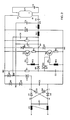
- FIG. 2 shows the exact circuit diagram of a circuit arrangement with a harmonic filter according to the invention for operating a low-pressure discharge lamp.
- a block of a current-compensated filter choke FD and a filter capacitor C1 are connected in parallel to the input of the mains rectifier in each supply line.
- This high-frequency filter is followed by the line rectifier with diodes D1 to D4 and a backup capacitor C2 parallel to the DC output.
- the self-regulating push-pull frequency generator consists of the two transistors T1, T2 with the reverse current diodes D6, D7, the series resistors R2 to R5, the control transformer and the starting generator with the resistors R1, R6, the starting capacitor C3, the diode D5 and the diac DC.
- the control transformer works according to the feedback principle and is composed of the primary winding RK1 and the two secondary windings RK2 and RK3.
- the lamp LP1 is connected with a connection of the electrode E1 to the center tap M1 between the two transistors T1, T2 and with a connection of the other electrode E2 to the positive pole of the mains rectifier.
- a series resonance circuit consisting of resonance inductance L1, Coupling capacitor C5 and resonance capacitor C6 are provided, the resonance inductor L1 and the coupling capacitor C5 being connected between the primary winding RK1 of the control transformer and the corresponding connection of the electrode E1 and the resonance capacitor C6 between the connections of the electrodes E1 and E2 on the heating circuit side.
- a smoothing capacitor C4 In addition to the switching paths of the transistors T1, T2 there is a smoothing capacitor C4.
- the circuit arrangement also has a harmonic filter.
- the filter consists of two diodes D8, D9 connected in series and in the forward DC direction to the supporting capacitor C2, the center tap M2 between the two diodes D8, D9 via a capacitor C7 with the center tap M1 between the two transistors T1, T2 and a capacitor C8 is connected to the center tap M3 between the resonance inductor L1 and the coupling capacitor C5.
- the harmonic filter also contains two further diodes D10, D11 connected in series and in a forward DC direction, the center tap M4 between these two diodes D10, D11 via a capacitor C9 also with the center tap M1 between the two transistors T1, T2 is connected.
- cycle 1 follows again and the energy transport starts again.
- Energy is pumped into the smoothing capacitor C4 once per period of the RF operating frequency.
- the pump capacitors C7, C8, C9 are charged to the peak value of the mains voltage, then the voltage and thus the energy drop again.
- Energy is pumped into the smoothing capacitor C4 during the mains voltage half-wave in accordance with the instantaneous value of the pulsating DC voltage at the supporting capacitor C2, reduced by the energy stored in the resonance inductance L1.
- the following components list shows the circuit elements used for a circuit arrangement for operating a 36 W fluorescent lamp on 220 V AC voltage: FD: EF25, 50 mH C1: 68 nF, 250 V ⁇ D1 - D4: rectifier bridge circuit B250, C800 C2: 68 nF, 250 V ⁇ R1, R6: 510 k ⁇ C3: 47 nF, 250 V- D5: 1N4005 DC: N413M R2, R3: 8.2 ⁇ T1, T2: MJE13007 R4, R5: 0.68 ⁇ D6 - D11: RGP10J C6-C8: 10 nF, 400 V ⁇ RK1: 5 turns (13x7x5) RK2, RK3: 1 turn C4: 10 ⁇ F, 450 V- L1: EF25, 0.9 mH C5: 150 nF, 400 V- C9: 3.3 nF, 400 V ⁇
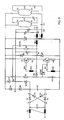
- FIG. 3 shows the exact circuit diagram of a circuit arrangement with a harmonic filter according to the invention for operating two low-pressure discharge lamps connected in parallel.
- the circuit arrangement largely corresponds to the circuit shown in FIG. 2.
- the lamp LP1 there is a further lamp LP2 with electrodes E3, E4 and, parallel to the first series resonance circuit, a second series resonance circuit comprising resonance inductor L1 ⁇ , coupling capacitor C5 ⁇ and resonance capacitance C6 ⁇ provided.
- the center tap M2 between the two first diodes D8, D9 is here connected to the center tap M3 in addition to the first capacitor C8 and additionally via the capacitor C8 ⁇ to the center tap M3 ⁇ between the resonance inductor L1 ⁇ and the coupling capacitor C5 ⁇ of the second resonant circuit.
Landscapes
- Circuit Arrangements For Discharge Lamps (AREA)
Priority Applications (1)
| Application Number | Priority Date | Filing Date | Title |
|---|---|---|---|
| AT87109551T ATE65661T1 (de) | 1986-07-14 | 1987-07-02 | Schaltungsanordnung zum betrieb von niederdruckentladungslampen. |
Applications Claiming Priority (2)
| Application Number | Priority Date | Filing Date | Title |
|---|---|---|---|
| DE3623749A DE3623749A1 (de) | 1986-07-14 | 1986-07-14 | Schaltungsanordnung zum betrieb von niederdruckentladungslampen |
| DE3623749 | 1986-07-14 |
Publications (3)
| Publication Number | Publication Date |
|---|---|
| EP0253224A2 true EP0253224A2 (fr) | 1988-01-20 |
| EP0253224A3 EP0253224A3 (en) | 1988-03-30 |
| EP0253224B1 EP0253224B1 (fr) | 1991-07-24 |
Family
ID=6305164
Family Applications (1)
| Application Number | Title | Priority Date | Filing Date |
|---|---|---|---|
| EP87109551A Expired - Lifetime EP0253224B1 (fr) | 1986-07-14 | 1987-07-02 | Disposition de circuit pour la mise en oeuvre de lampes à décharge basse-pression |
Country Status (5)
| Country | Link |
|---|---|
| US (1) | US4808887A (fr) |
| EP (1) | EP0253224B1 (fr) |
| JP (1) | JPH07101637B2 (fr) |
| AT (1) | ATE65661T1 (fr) |
| DE (2) | DE3623749A1 (fr) |
Cited By (11)
| Publication number | Priority date | Publication date | Assignee | Title |
|---|---|---|---|---|
| EP0389847A2 (fr) * | 1989-03-16 | 1990-10-03 | Korte, Heinrich | Circuit |
| EP0392834A1 (fr) * | 1989-04-14 | 1990-10-17 | TLG plc | Circuits ballast pour lampes à décharge |
| EP0392770A2 (fr) * | 1989-04-14 | 1990-10-17 | TLG plc | Circuits à ballast pour lampes à décharge |
| EP0441253A1 (fr) * | 1990-02-04 | 1991-08-14 | Gaash Lighting Industries | Ballast électronique pour lampes à décharge de gaz |
| WO1996007297A2 (fr) * | 1994-08-22 | 1996-03-07 | Philips Electronics N.V. | Configuration de circuit pour lampe a decharge comprenant un convertisseur de courant continu en courant alternatif et un circuit de resonance |
| DE19518096A1 (de) * | 1995-05-17 | 1996-11-21 | Ceag Sicherheitstechnik Gmbh | Elektronisches Vorschaltgerät und dessen Betriebsverfahren |
| EP0808085A2 (fr) * | 1996-05-15 | 1997-11-19 | Patent-Treuhand-Gesellschaft für elektrische Glühlampen mbH | Alimentation à haute fréquence pour une lampe à décharge basse pression avec une compatibilité électromagnétique accrue |
| WO1998058526A1 (fr) * | 1997-06-18 | 1998-12-23 | Patent-Treuhand-Gesellschaft für elektrische Glühlampen mbH | Bobine d'inductance support de pompage |
| EP1028606A2 (fr) * | 1999-02-11 | 2000-08-16 | Patent-Treuhand-Gesellschaft für elektrische Glühlampen mbH | Circuit pour alimenter au moins une lampe à décharge à basse pression |
| EP1056188A2 (fr) * | 1999-05-20 | 2000-11-29 | Patent-Treuhand-Gesellschaft für elektrische Glühlampen mbH | Circuit de correction du facteur de puissance |
| WO2004028218A1 (fr) * | 2002-09-12 | 2004-04-01 | Tridonicatco Gmbh & Co. Kg | Appareil electronique auxiliaire muni d'une lampe de charge pour la correction active du facteur de puissance |
Families Citing this family (42)
| Publication number | Priority date | Publication date | Assignee | Title |
|---|---|---|---|---|
| US5977721A (en) * | 1983-02-22 | 1999-11-02 | Nilssen; Ole K. | Controlled power-factor-corrected ballast |
| US5710488A (en) * | 1986-12-22 | 1998-01-20 | Nilssen; Ole K. | Low-frequency high-efficacy electronic ballast |
| DE3841227A1 (de) * | 1988-12-07 | 1990-06-13 | Patent Treuhand Ges Fuer Elektrische Gluehlampen Mbh | Schaltungsanordnung zum betrieb einer niederdruckentladungslampe |
| US5225741A (en) * | 1989-03-10 | 1993-07-06 | Bruce Industries, Inc. | Electronic ballast and power controller |
| DE4032329A1 (de) * | 1990-10-11 | 1992-04-16 | May & Christe Gmbh | Schaltungsanordnung zum hochfrequenten betrieb von gasentladungslampen mit pulsierender gleichspannung |
| US5130611A (en) * | 1991-01-16 | 1992-07-14 | Intent Patents A.G. | Universal electronic ballast system |
| CN1020536C (zh) * | 1991-09-18 | 1993-05-05 | 杜荣久 | 电子镇流器 |
| GB9226533D0 (en) * | 1992-12-21 | 1993-02-17 | Control & Readout Limited | A switch mode power supply with power factor correction |
| US5374875A (en) * | 1993-02-16 | 1994-12-20 | Motorola Lighting, Inc. | High-power factor circuit for energizing gas discharge lamps |
| US5477112A (en) * | 1993-04-27 | 1995-12-19 | Electronic Lighting, Inc. | Ballasting network with integral trap |
| US5345164A (en) * | 1993-04-27 | 1994-09-06 | Metcal, Inc. | Power factor corrected DC power supply |
| US5434480A (en) * | 1993-10-12 | 1995-07-18 | Bobel; Andrzej A. | Electronic device for powering a gas discharge road from a low frequency source |
| US5412287A (en) * | 1993-12-09 | 1995-05-02 | Motorola Lighting, Inc. | Circuit for powering a gas discharge lamp |
| US5416388A (en) * | 1993-12-09 | 1995-05-16 | Motorola Lighting, Inc. | Electronic ballast with two transistors and two transformers |
| US5396153A (en) * | 1993-12-09 | 1995-03-07 | Motorola Lighting, Inc. | Protection circuit for electronic ballasts which use charge pump power factor correction |
| DE4406083A1 (de) * | 1994-02-24 | 1995-08-31 | Patent Treuhand Ges Fuer Elektrische Gluehlampen Mbh | Schaltungsanordnung zum Betrieb mindestens einer Niederdruckentladungslampe |
| DE4410492A1 (de) * | 1994-03-25 | 1995-09-28 | Patent Treuhand Ges Fuer Elektrische Gluehlampen Mbh | Schaltungsanordnung zum Betrieb von Niederdruckentladungslampen |
| DE4421336C2 (de) * | 1994-06-17 | 2002-09-26 | Miele & Cie | Beleuchtungseinrichtung in einem Mikrowellengerät |
| DE9410910U1 (de) * | 1994-07-07 | 1995-11-02 | Patent Treuhand Ges Fuer Elektrische Gluehlampen Mbh | Schaltungsanordnung zum Betrieb von Niederdruckentladungslampen |
| DE4425859A1 (de) * | 1994-07-21 | 1996-01-25 | Patent Treuhand Ges Fuer Elektrische Gluehlampen Mbh | Schaltungsanordnung zum Betrieb einer oder mehrerer Niederdruckentladungslampen |
| DE4430397A1 (de) * | 1994-08-26 | 1996-02-29 | Patent Treuhand Ges Fuer Elektrische Gluehlampen Mbh | Schaltungsanordnung zum Betrieb von Niederdruckentladungslampen |
| US5608295A (en) * | 1994-09-02 | 1997-03-04 | Valmont Industries, Inc. | Cost effective high performance circuit for driving a gas discharge lamp load |
| US5488269A (en) | 1995-02-10 | 1996-01-30 | General Electric Company | Multi-resonant boost high power factor circuit |
| US6057652A (en) * | 1995-09-25 | 2000-05-02 | Matsushita Electric Works, Ltd. | Power supply for supplying AC output power |
| TW296894U (en) * | 1995-11-21 | 1997-01-21 | Philips Electronics Nv | Circuit arrangement |
| US5703438A (en) * | 1996-01-22 | 1997-12-30 | Valmont Industries, Inc. | Line current filter for less than 10% total harmonic distortion |
| US5801492A (en) * | 1996-05-30 | 1998-09-01 | Bobel; Andrzej | Electronic ballast for gas discharge lamp having primary and auxiliary resonant circuits |
| US5994848A (en) * | 1997-04-10 | 1999-11-30 | Philips Electronics North America Corporation | Triac dimmable, single stage compact flourescent lamp |
| US6034485A (en) * | 1997-11-05 | 2000-03-07 | Parra; Jorge M. | Low-voltage non-thermionic ballast-free energy-efficient light-producing gas discharge system and method |
| US5998941A (en) * | 1997-08-21 | 1999-12-07 | Parra; Jorge M. | Low-voltage high-efficiency fluorescent signage, particularly exit sign |
| US5982159A (en) * | 1997-07-31 | 1999-11-09 | Philips Electronics North America Corporation | Dimmable, single stage fluorescent lamp |
| US5917717A (en) * | 1997-07-31 | 1999-06-29 | U.S. Philips Corporation | Ballast dimmer with passive power feedback control |
| US6300722B1 (en) | 1997-11-05 | 2001-10-09 | Jorge M. Parra | Non-thermionic ballast-free energy-efficient light-producing gas discharge system and method |
| DE19815623A1 (de) * | 1998-04-07 | 1999-10-14 | Patent Treuhand Ges Fuer Elektrische Gluehlampen Mbh | Schaltungsanordnung zum Betrieb von Niederdruckentladungslampen |
| US6411041B1 (en) | 1999-06-02 | 2002-06-25 | Jorge M. Parra | Non-thermionic fluorescent lamps and lighting systems |
| US6465971B1 (en) | 1999-06-02 | 2002-10-15 | Jorge M. Parra | Plastic “trofer” and fluorescent lighting system |
| JP2003515876A (ja) * | 1999-11-19 | 2003-05-07 | コーニンクレッカ フィリップス エレクトロニクス エヌ ヴィ | 高周波電流によって放電ランプを作動させる回路装置 |
| FI107579B (fi) * | 2000-02-15 | 2001-08-31 | Tapani Martti Sakari Saikka | Valaistusjärjestelmä |
| US7057375B2 (en) * | 2002-03-21 | 2006-06-06 | Patent Treuhand Gesellschaft Fur Elektrische Gluhlampen Mbh | Power factor correction |
| US6936973B2 (en) * | 2002-05-31 | 2005-08-30 | Jorge M. Parra, Sr. | Self-oscillating constant-current gas discharge device lamp driver and method |
| CN101144962B (zh) * | 2006-09-12 | 2011-07-27 | 佳世达科技股份有限公司 | 电子装置及其功率因素改善回路 |
| US8035318B2 (en) * | 2008-06-30 | 2011-10-11 | Neptun Light, Inc. | Apparatus and method enabling fully dimmable operation of a compact fluorescent lamp |
Citations (2)
| Publication number | Priority date | Publication date | Assignee | Title |
|---|---|---|---|---|
| US4075476A (en) * | 1976-12-20 | 1978-02-21 | Gte Sylvania Incorporated | Sinusoidal wave oscillator ballast circuit |
| US4563719A (en) * | 1982-08-30 | 1986-01-07 | Nilssen Ole K | Ballasts with built-in ground-fault protection |
Family Cites Families (12)
| Publication number | Priority date | Publication date | Assignee | Title |
|---|---|---|---|---|
| US4277726A (en) * | 1978-08-28 | 1981-07-07 | Litton Systems, Inc. | Solid-state ballast for rapid-start type fluorescent lamps |
| DE2941822A1 (de) * | 1979-10-16 | 1981-04-30 | Patra Patent Treuhand | Vorschaltanordnung zum betreiben von niederdruckentladungslampen |
| US4388562A (en) * | 1980-11-06 | 1983-06-14 | Astec Components, Ltd. | Electronic ballast circuit |
| DE3112577A1 (de) * | 1981-03-30 | 1982-10-14 | Patra Patent Treuhand | Vorschaltanordnung zum betreiben von niederdruckentladungslampen |
| DE3112499A1 (de) * | 1981-03-30 | 1982-10-14 | Patra Patent Treuhand | Vorschaltanordnung zum betreiben von niederdruckentladungslampen |
| JPS57191950A (en) * | 1981-05-22 | 1982-11-25 | Hitachi Ltd | Charged-particle source |
| AU555174B2 (en) * | 1981-09-18 | 1986-09-18 | Oy Helvar | Electronic ballast for a discharge lamp |
| US4481460A (en) * | 1982-02-08 | 1984-11-06 | Siemens Aktiengesellschaft | Inverter with charging regulator having a variable keying ratio |
| GB2124042B (en) * | 1982-06-01 | 1986-10-01 | Control Logic | Reduction of harmonics in gas discharge lamp ballasts |
| DE3301632A1 (de) * | 1983-01-19 | 1984-07-26 | Siemens AG, 1000 Berlin und 8000 München | Umrichter |
| NL8402351A (nl) * | 1984-07-26 | 1986-02-17 | Philips Nv | Gelijkstroom-wisselstroomomzetter voor het voeden van een metaaldampontladingsbuis. |
| DE3608615A1 (de) * | 1986-03-14 | 1987-09-17 | Patent Treuhand Ges Fuer Elektrische Gluehlampen Mbh | Schaltungsanordnung zum betrieb von niederdruckentladungslampen |
-
1986
- 1986-07-14 DE DE3623749A patent/DE3623749A1/de not_active Withdrawn
-
1987
- 1987-07-02 AT AT87109551T patent/ATE65661T1/de not_active IP Right Cessation
- 1987-07-02 EP EP87109551A patent/EP0253224B1/fr not_active Expired - Lifetime
- 1987-07-02 DE DE8787109551T patent/DE3771599D1/de not_active Expired - Lifetime
- 1987-07-06 US US07/069,857 patent/US4808887A/en not_active Expired - Lifetime
- 1987-07-14 JP JP62174042A patent/JPH07101637B2/ja not_active Expired - Fee Related
Patent Citations (2)
| Publication number | Priority date | Publication date | Assignee | Title |
|---|---|---|---|---|
| US4075476A (en) * | 1976-12-20 | 1978-02-21 | Gte Sylvania Incorporated | Sinusoidal wave oscillator ballast circuit |
| US4563719A (en) * | 1982-08-30 | 1986-01-07 | Nilssen Ole K | Ballasts with built-in ground-fault protection |
Cited By (21)
| Publication number | Priority date | Publication date | Assignee | Title |
|---|---|---|---|---|
| US5070276A (en) * | 1989-03-16 | 1991-12-03 | Heinrich Korte | Lamp supply circuit |
| EP0389847A3 (fr) * | 1989-03-16 | 1992-03-04 | Korte, Heinrich | Circuit |
| EP0389847A2 (fr) * | 1989-03-16 | 1990-10-03 | Korte, Heinrich | Circuit |
| EP0392834A1 (fr) * | 1989-04-14 | 1990-10-17 | TLG plc | Circuits ballast pour lampes à décharge |
| EP0392770A2 (fr) * | 1989-04-14 | 1990-10-17 | TLG plc | Circuits à ballast pour lampes à décharge |
| EP0392770A3 (fr) * | 1989-04-14 | 1992-02-12 | TLG plc | Circuits à ballast pour lampes à décharge |
| EP0441253A1 (fr) * | 1990-02-04 | 1991-08-14 | Gaash Lighting Industries | Ballast électronique pour lampes à décharge de gaz |
| CN1075336C (zh) * | 1994-08-22 | 2001-11-21 | 皇家菲利浦电子有限公司 | 电路设备 |
| WO1996007297A2 (fr) * | 1994-08-22 | 1996-03-07 | Philips Electronics N.V. | Configuration de circuit pour lampe a decharge comprenant un convertisseur de courant continu en courant alternatif et un circuit de resonance |
| WO1996007297A3 (fr) * | 1994-08-22 | 1996-05-30 | Philips Electronics Nv | Configuration de circuit pour lampe a decharge comprenant un convertisseur de courant continu en courant alternatif et un circuit de resonance |
| DE19518096A1 (de) * | 1995-05-17 | 1996-11-21 | Ceag Sicherheitstechnik Gmbh | Elektronisches Vorschaltgerät und dessen Betriebsverfahren |
| EP0808085A2 (fr) * | 1996-05-15 | 1997-11-19 | Patent-Treuhand-Gesellschaft für elektrische Glühlampen mbH | Alimentation à haute fréquence pour une lampe à décharge basse pression avec une compatibilité électromagnétique accrue |
| EP0808085A3 (fr) * | 1996-05-15 | 1998-11-18 | Patent-Treuhand-Gesellschaft für elektrische Glühlampen mbH | Alimentation à haute fréquence pour une lampe à décharge basse pression avec une compatibilité électromagnétique accrue |
| WO1998058526A1 (fr) * | 1997-06-18 | 1998-12-23 | Patent-Treuhand-Gesellschaft für elektrische Glühlampen mbH | Bobine d'inductance support de pompage |
| US6091207A (en) * | 1997-06-18 | 2000-07-18 | Patent-Treuhand-Gesellschaft Fuer Elektrische Gluelampen Mbh | Pump support choke |
| AU741384B2 (en) * | 1997-06-18 | 2001-11-29 | Patent-Treuhand-Gesellschaft Fur Elektrische Gluhlampen Mbh | Pump support choke |
| EP1028606A2 (fr) * | 1999-02-11 | 2000-08-16 | Patent-Treuhand-Gesellschaft für elektrische Glühlampen mbH | Circuit pour alimenter au moins une lampe à décharge à basse pression |
| EP1028606A3 (fr) * | 1999-02-11 | 2003-03-19 | Patent-Treuhand-Gesellschaft für elektrische Glühlampen mbH | Circuit pour alimenter au moins une lampe à décharge à basse pression |
| EP1056188A2 (fr) * | 1999-05-20 | 2000-11-29 | Patent-Treuhand-Gesellschaft für elektrische Glühlampen mbH | Circuit de correction du facteur de puissance |
| EP1056188A3 (fr) * | 1999-05-20 | 2001-12-12 | Patent-Treuhand-Gesellschaft für elektrische Glühlampen mbH | Circuit de correction du facteur de puissance |
| WO2004028218A1 (fr) * | 2002-09-12 | 2004-04-01 | Tridonicatco Gmbh & Co. Kg | Appareil electronique auxiliaire muni d'une lampe de charge pour la correction active du facteur de puissance |
Also Published As
| Publication number | Publication date |
|---|---|
| JPH07101637B2 (ja) | 1995-11-01 |
| EP0253224A3 (en) | 1988-03-30 |
| ATE65661T1 (de) | 1991-08-15 |
| US4808887A (en) | 1989-02-28 |
| DE3771599D1 (de) | 1991-08-29 |
| DE3623749A1 (de) | 1988-01-21 |
| EP0253224B1 (fr) | 1991-07-24 |
| JPS6329496A (ja) | 1988-02-08 |
Similar Documents
| Publication | Publication Date | Title |
|---|---|---|
| EP0253224B1 (fr) | Disposition de circuit pour la mise en oeuvre de lampes à décharge basse-pression | |
| EP0244644B1 (fr) | Disposition de circuit pour lampes à décharge basse pression travaillant en haute fréquence | |
| EP0372303B1 (fr) | Circuit pour le fonctionnement d'une lampe de décharge à basse pression | |
| EP0264765B1 (fr) | Disposition de circuit pour la mise en oeuvre de lampe à incandescence halogène basse tension | |
| EP0356818B1 (fr) | Circuit alimentant une charge | |
| DE3805510A1 (de) | Schaltungsanordnung zum betrieb einer niederdruckentladungslampe | |
| EP0699016A2 (fr) | Circuit pour alimenter des lampes à décharge basse pression | |
| DE69817992T2 (de) | Elektronisches vorschaltgerät | |
| EP1092260B1 (fr) | Circuit de correction du facteur de puissance | |
| EP0541909B1 (fr) | Circuit pour alimenter des lampes à décharge | |
| EP0808085B1 (fr) | Alimentation à haute fréquence pour une lampe à décharge basse pression avec une compatibilité électromagnétique accrue | |
| EP0600340B1 (fr) | Circuit passif pour améliorer le facteur de puissance | |
| EP1553810B1 (fr) | Dispositif d'alimentation de sources lumineuses avec correction du facteur de puissance | |
| EP0691800A2 (fr) | Circuit pour alimenter des lampes à décharge basse-pression | |
| EP0276460B1 (fr) | Disposition de circuit pour mettre en oeuvre une lampe à décharge basse pression | |
| EP0697803B1 (fr) | Circuit pour alimenter des lampes à décharge | |
| EP1028606B1 (fr) | Circuit pour alimenter au moins une lampe à décharge à basse pression | |
| EP0949851B1 (fr) | Ballast pour lampe à décharge à faible pression | |
| DE60108315T2 (de) | Elektronisches vorschaltgerät | |
| EP1553811B1 (fr) | Dispositif d'alimentation de sources lumineuses avec correction du facteur de puissance | |
| EP0707436A2 (fr) | Circuit pour alimenter des lampes à incandescence | |
| EP0671867B1 (fr) | Circuit d'alimentation de lampes à décharge | |
| EP0585727B1 (fr) | Onduleur avec deux capacités de filtrage en série | |
| DE10204433A1 (de) | Gleichspannungskonverter für ein Leuchtenbetriebsgerät | |
| EP0596397A1 (fr) | Circuit d'alimentation à haute fréquence |
Legal Events
| Date | Code | Title | Description |
|---|---|---|---|
| PUAI | Public reference made under article 153(3) epc to a published international application that has entered the european phase |
Free format text: ORIGINAL CODE: 0009012 |
|
| AK | Designated contracting states |
Kind code of ref document: A2 Designated state(s): AT BE CH DE FR GB IT LI NL SE |
|
| PUAL | Search report despatched |
Free format text: ORIGINAL CODE: 0009013 |
|
| AK | Designated contracting states |
Kind code of ref document: A3 Designated state(s): AT BE CH DE FR GB IT LI NL SE |
|
| 17P | Request for examination filed |
Effective date: 19880506 |
|
| RAP3 | Party data changed (applicant data changed or rights of an application transferred) |
Owner name: PATENT-TREUHAND-GESELLSCHAFT FUER ELEKTRISCHE GLUE |
|
| 17Q | First examination report despatched |
Effective date: 19901212 |
|
| GRAA | (expected) grant |
Free format text: ORIGINAL CODE: 0009210 |
|
| AK | Designated contracting states |
Kind code of ref document: B1 Designated state(s): AT BE CH DE FR GB IT LI NL SE |
|
| REF | Corresponds to: |
Ref document number: 65661 Country of ref document: AT Date of ref document: 19910815 Kind code of ref document: T |
|
| REF | Corresponds to: |
Ref document number: 3771599 Country of ref document: DE Date of ref document: 19910829 |
|
| ET | Fr: translation filed | ||
| ITF | It: translation for a ep patent filed |
Owner name: STUDIO JAUMANN |
|
| GBT | Gb: translation of ep patent filed (gb section 77(6)(a)/1977) | ||
| PLBI | Opposition filed |
Free format text: ORIGINAL CODE: 0009260 |
|
| 26 | Opposition filed |
Opponent name: OTTO ECKERLE GMBH & CO. KG Effective date: 19920423 |
|
| NLR1 | Nl: opposition has been filed with the epo |
Opponent name: OTTO ECKERLE GMBH & CO. KG |
|
| PLBM | Termination of opposition procedure: date of legal effect published |
Free format text: ORIGINAL CODE: 0009276 |
|
| STAA | Information on the status of an ep patent application or granted ep patent |
Free format text: STATUS: OPPOSITION PROCEDURE CLOSED |
|
| 27C | Opposition proceedings terminated |
Effective date: 19921107 |
|
| NLR2 | Nl: decision of opposition | ||
| EAL | Se: european patent in force in sweden |
Ref document number: 87109551.9 |
|
| REG | Reference to a national code |
Ref country code: GB Ref legal event code: IF02 |
|
| PGFP | Annual fee paid to national office [announced via postgrant information from national office to epo] |
Ref country code: AT Payment date: 20050615 Year of fee payment: 19 |
|
| PGFP | Annual fee paid to national office [announced via postgrant information from national office to epo] |
Ref country code: NL Payment date: 20050705 Year of fee payment: 19 |
|
| PGFP | Annual fee paid to national office [announced via postgrant information from national office to epo] |
Ref country code: SE Payment date: 20050707 Year of fee payment: 19 |
|
| PGFP | Annual fee paid to national office [announced via postgrant information from national office to epo] |
Ref country code: BE Payment date: 20050722 Year of fee payment: 19 |
|
| PGFP | Annual fee paid to national office [announced via postgrant information from national office to epo] |
Ref country code: CH Payment date: 20051013 Year of fee payment: 19 |
|
| PG25 | Lapsed in a contracting state [announced via postgrant information from national office to epo] |
Ref country code: AT Free format text: LAPSE BECAUSE OF NON-PAYMENT OF DUE FEES Effective date: 20060702 |
|
| PG25 | Lapsed in a contracting state [announced via postgrant information from national office to epo] |
Ref country code: SE Free format text: LAPSE BECAUSE OF NON-PAYMENT OF DUE FEES Effective date: 20060703 |
|
| PGFP | Annual fee paid to national office [announced via postgrant information from national office to epo] |
Ref country code: GB Payment date: 20060707 Year of fee payment: 20 |
|
| PGFP | Annual fee paid to national office [announced via postgrant information from national office to epo] |
Ref country code: FR Payment date: 20060727 Year of fee payment: 20 |
|
| PG25 | Lapsed in a contracting state [announced via postgrant information from national office to epo] |
Ref country code: LI Free format text: LAPSE BECAUSE OF NON-PAYMENT OF DUE FEES Effective date: 20060731 Ref country code: BE Free format text: LAPSE BECAUSE OF NON-PAYMENT OF DUE FEES Effective date: 20060731 Ref country code: CH Free format text: LAPSE BECAUSE OF NON-PAYMENT OF DUE FEES Effective date: 20060731 |
|
| PGFP | Annual fee paid to national office [announced via postgrant information from national office to epo] |
Ref country code: IT Payment date: 20060731 Year of fee payment: 20 |
|
| PGFP | Annual fee paid to national office [announced via postgrant information from national office to epo] |
Ref country code: DE Payment date: 20060918 Year of fee payment: 20 |
|
| PG25 | Lapsed in a contracting state [announced via postgrant information from national office to epo] |
Ref country code: NL Free format text: LAPSE BECAUSE OF NON-PAYMENT OF DUE FEES Effective date: 20070201 |
|
| REG | Reference to a national code |
Ref country code: CH Ref legal event code: PL |
|
| EUG | Se: european patent has lapsed | ||
| NLV4 | Nl: lapsed or anulled due to non-payment of the annual fee |
Effective date: 20070201 |
|
| REG | Reference to a national code |
Ref country code: GB Ref legal event code: PE20 |
|
| PG25 | Lapsed in a contracting state [announced via postgrant information from national office to epo] |
Ref country code: GB Free format text: LAPSE BECAUSE OF EXPIRATION OF PROTECTION Effective date: 20070701 |
|
| BERE | Be: lapsed |
Owner name: *PATENT-TREUHAND G.- FUR ELEKTRISCHE GLUHLAMPEN M. Effective date: 20060731 |