EP0251964B1 - Entlüftungsdruckrolle - Google Patents
Entlüftungsdruckrolle Download PDFInfo
- Publication number
- EP0251964B1 EP0251964B1 EP87450015A EP87450015A EP0251964B1 EP 0251964 B1 EP0251964 B1 EP 0251964B1 EP 87450015 A EP87450015 A EP 87450015A EP 87450015 A EP87450015 A EP 87450015A EP 0251964 B1 EP0251964 B1 EP 0251964B1
- Authority
- EP
- European Patent Office
- Prior art keywords
- pressure roller
- roller
- shaft
- axis
- joined
- Prior art date
- Legal status (The legal status is an assumption and is not a legal conclusion. Google has not performed a legal analysis and makes no representation as to the accuracy of the status listed.)
- Expired - Lifetime
Links
- 239000004744 fabric Substances 0.000 description 4
- 239000011295 pitch Substances 0.000 description 4
- 238000004519 manufacturing process Methods 0.000 description 3
- 239000002184 metal Substances 0.000 description 2
- 238000000605 extraction Methods 0.000 description 1
- 239000000463 material Substances 0.000 description 1
- 238000006116 polymerization reaction Methods 0.000 description 1
- 230000000750 progressive effect Effects 0.000 description 1
- 239000011347 resin Substances 0.000 description 1
- 229920005989 resin Polymers 0.000 description 1
- 238000003466 welding Methods 0.000 description 1
Images

Classifications
-
- B—PERFORMING OPERATIONS; TRANSPORTING
- B29—WORKING OF PLASTICS; WORKING OF SUBSTANCES IN A PLASTIC STATE IN GENERAL
- B29C—SHAPING OR JOINING OF PLASTICS; SHAPING OF MATERIAL IN A PLASTIC STATE, NOT OTHERWISE PROVIDED FOR; AFTER-TREATMENT OF THE SHAPED PRODUCTS, e.g. REPAIRING
- B29C37/00—Component parts, details, accessories or auxiliary operations, not covered by group B29C33/00 or B29C35/00
- B29C37/006—Degassing moulding material or draining off gas during moulding
- B29C37/0064—Degassing moulding material or draining off gas during moulding of reinforced material
Definitions
- the present invention relates to an apparatus intended to allow better evacuation of air bubbles held captive, in particular in impregnated tissues, such an apparatus being commonly called a bubble separator.
- the object of the invention is precisely to propose a new type of roller specifically adapted to this use and capable of efficiently and easily ensuring bubble removal.
- the subject of the invention is a bubble pressure roller for apparatus of the type comprising at least one carrier shaft secured to a part itself carrying a vibrator generating vibrations whose direction is substantially perpendicular to said carrier shaft, said roller being characterized in that it consists of two identical half-rollers arranged coaxially and mounted free in rotation on two internal cylindrical sleeves fixed on the two ends of said carrier shaft by a hinge giving a slight angular movement, only in a plane perpendicular to the work plane and in the direction of advancement of the device, of the axis of each half-roller with respect to the axis of the carrier shaft, the latter being integral in its central part with a removable part of connection to the frame of said device.
- said internal cylindrical sleeve of each half-roller is threaded onto one of the ends of the support shaft, which is spherical, of diameter corresponding to that of said sleeve and crossed by a pin whose ends are integral with the sleeve and whose axis is orthogonal, on the one hand, to the axis of the shaft and, on the other hand, to the direction of application of said vibrations, said spherical part being substantially in the central part of the roller.
- each half-roller comprises, from one end to the other, a continuous helical groove, the protruding parts delimited by this groove having threads of opposite direction to that throat and depth and not significantly lower than the latter.
- the end parts of the half-rollers are rounded, said projecting parts with their threads being these places of height progressively reduced in the direction of the ends of the half-rollers.
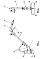
- the device shown in Figures 1 and 2 comprises a pressure roller consisting of two identical half-rollers 1a, 1b carried by a common shaft itself secured to a part 2 in the form of T fixed to the end of a vibrator assembly 3 capable of applying vibrations to said shaft in a direction perpendicular to the latter.
- the assembly 2-3 is mounted at the end of a handle formed by an arm 4 and an elongated metal cylinder 5 serving for the supply of compressed air by hoses 6 of the vibrator 3.
- the handle 4-5 is shaped at its end as a handle 7 provided with a control lever 8 and a connector 9 for connection to a source of compressed air (not shown).
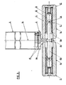
- rollers are shown in detail in FIGS. 3 to 5.
- the two rollers 1a, 1 are identical coaxial and symmetrically arranged with respect to the T-piece 2, a part 2a of which forms a connection flange by screw to the end face of the cylindrical block of the vibrator 3 and a part 2b perpendicular to part 2a is fixed for example by welding to a shaft in its central part.
- This tree is in the form of two half-shafts 10a, 10b on each of which is threaded one of the rollers 1a, 1b.
- Each roller comprises a cylindrical sleeve 11, for example made of a suitable plastic material, in the interior recess of which is mounted in a journalling manner a metal sleeve 12 having a cylindrical internal space 13 in which is engaged a spherical prominence 14 integral with the end of the half tree 10a, 10b considered.
- the diameter of the prominence 14 is slightly greater than that of the half-shafts and equal to that of the cylindrical space 13.
- a pin 15 passes diametrically through the spherical part 14 while being fixed at its ends to the sleeve 12.
- the axis of the pin 15 is perpendicular both to the axis of the shaft 1 Oa, 1 Ob and to the direction, symbolized at 16 in FIG. 3, the application of vibrations by the vibrator 3 to said roller-carrying shaft.
- the pin 15 is arranged so as to allow free angular movement of the axis of each roller around the axis of the pin, relative to the axis of the shaft 10a, 10b.
- the amplitude of this movement is for example from 5 to 10 °.
- the internal arrangement of the rollers, on the part side 2, is made so as to allow this free movement, sufficient space being provided between the end of the rollers and said part 2.
- the outer surface of the rollers is cylindrical except in the vicinity of the ends, at 17, where the edge is broken and has very specific characteristics.
- This surface is in fact traversed over the entire length of the roller 1a, 1 by a continuous helical groove 18 for example with a pitch to the left of 6mm, a depth of 2mm for an external diameter of the roller of 40mm and a width of 3mm.
- the helical projection 19 delimited by the groove is itself provided with threads 20 of dimensions substantially smaller than those of the groove 18 and having a noticeably reduced pitch and to the right as can be seen in FIG. 5 which represents part of the surface of a roller in its middle zone.
- the threads 20 have for example a width, from crest to crest, of 1.5mm, a depth of 1 mm, the pitch being 1.5mm.
- edges separating the threads 20 are slightly blunt at 21.
- This line 22 provides a progressive connection with the sides of the rollers and substantially and progressively erases the edges of the threads 20 closest to the ends of the rollers to the point that the end thread 20, as shown at 23 in FIG. 4, is practically entirely truncated. .
- the device according to the invention makes it possible to closely match the curved surfaces of impregnated fabrics to be debubbled, in particular in the case of the manufacture of boat hulls, by virtue of the angular deflections, only in a plane perpendicular both to the working plane and to the direction of advancement of the device, of the rollers 1 a, 1 b around the pins 15, the axes of the rollers then forming between them an angle less than or greater than 180 ° depending on whether the rollers are pressed on a concave surface or convex.
- each roller 1a, 1b can be pressed and roll on the surface to be deburred with a pressure distributed substantially regularly from one end to the other of the roller, which provides very good homogeneity on debubbling.
- the vibrations are communicated directly and without attenuation at the periphery of the rollers thanks to the spherical part 14 totally integral with the carrier shaft, the part 2 and the carcass of the vibrator 3, and which is in direct and constant contact with the sleeve. internal 12, whatever the inclination of the axis of the roller on the axis of the carrier shaft, said spherical part 14 being located substantially in the center of the roller.
- the morphology of the outer surface of the rollers is remarkably effective. Indeed, the existence of grooves or threads 18,20 of different characteristics and in particular of opposite pitches, provides an excellent and regular evacuation of the bubbles trapped in the impregnated fabrics.
- the assembly 10a, 10b; 1 a, bb is easily removable and can be replaced instantly by another set, the rollers of which have different characteristics better suited to the work to be performed, such as the diameter, the length, the angular movement, the dimensions and arrangements of the grooves or threads surface area 18.20.
- the invention is obviously not limited to the embodiment shown and described above, but on the contrary covers all variants thereof, in particular as regards the articulated mounting means of the rollers 1a, 1b at the ends of the shaft. support and configuration of the active surface of the rollers.
- the device represented in FIGS. 1 and 2 could comprise two pairs of rollers 1a, 1b, aligned on the same axis, each pair being connected, by a piece such as 2, to the end of the block of the vibrator 3, said parts themselves being preferably articulated about an axis parallel to the direction of advance of the device.
- Such a device offers a much greater working width.
Landscapes
- Rolls And Other Rotary Bodies (AREA)
- Paper (AREA)
- Nonmetallic Welding Materials (AREA)
- Yarns And Mechanical Finishing Of Yarns Or Ropes (AREA)
- Machines For Manufacturing Corrugated Board In Mechanical Paper-Making Processes (AREA)
- Absorbent Articles And Supports Therefor (AREA)
- Friction Gearing (AREA)
Claims (5)
Priority Applications (1)
| Application Number | Priority Date | Filing Date | Title |
|---|---|---|---|
| AT87450015T ATE56387T1 (de) | 1986-06-24 | 1987-06-24 | Entlueftungsdruckrolle. |
Applications Claiming Priority (2)
| Application Number | Priority Date | Filing Date | Title |
|---|---|---|---|
| FR8609243A FR2600678B1 (fr) | 1986-06-24 | 1986-06-24 | Rouleau presseur debulleur |
| FR8609243 | 1986-06-24 |
Publications (2)
| Publication Number | Publication Date |
|---|---|
| EP0251964A1 EP0251964A1 (de) | 1988-01-07 |
| EP0251964B1 true EP0251964B1 (de) | 1990-09-12 |
Family
ID=9336724
Family Applications (1)
| Application Number | Title | Priority Date | Filing Date |
|---|---|---|---|
| EP87450015A Expired - Lifetime EP0251964B1 (de) | 1986-06-24 | 1987-06-24 | Entlüftungsdruckrolle |
Country Status (6)
| Country | Link |
|---|---|
| EP (1) | EP0251964B1 (de) |
| AT (1) | ATE56387T1 (de) |
| DE (1) | DE3764882D1 (de) |
| ES (1) | ES2017756B3 (de) |
| FR (1) | FR2600678B1 (de) |
| GR (1) | GR3001092T3 (de) |
Families Citing this family (2)
| Publication number | Priority date | Publication date | Assignee | Title |
|---|---|---|---|---|
| FR2650529B1 (fr) * | 1989-08-03 | 1991-11-08 | Aerospatiale | Dispositif applicateur pour machine de nappage au moyen de ruban de matiere composite |
| CN110744909B (zh) * | 2019-11-14 | 2023-05-23 | 海宁帝龙永孚新材料有限公司 | 一种贴合对花pvc装饰膜的压合辊子及其制备方法 |
Family Cites Families (6)
| Publication number | Priority date | Publication date | Assignee | Title |
|---|---|---|---|---|
| US2321511A (en) * | 1942-08-12 | 1943-06-08 | Piercy William | Paint applying device |
| FR1520199A (fr) * | 1967-04-24 | 1968-04-05 | Bristol Aeroplane Plastics Ltd | Perfectionnement apporté à la fabrication des structures en matière plastique renforcée par des fibres de verre |
| US3717899A (en) * | 1970-12-17 | 1973-02-27 | Republic Corp | Resin radius roller |
| US3970396A (en) * | 1975-06-18 | 1976-07-20 | Brady William J | Paint applicator |
| DE2841085C2 (de) * | 1978-09-21 | 1986-10-16 | Maschinenfabrik Otto Baier Gmbh, 7140 Ludwigsburg | Gerät, insbesondere Handgerät, mit einer Stachelwalze |
| FR2566014B1 (fr) * | 1984-06-15 | 1986-12-19 | Dias Alain | Appareil manuel de pressage de tissus impregnes |
-
1986
- 1986-06-24 FR FR8609243A patent/FR2600678B1/fr not_active Expired
-
1987
- 1987-06-24 EP EP87450015A patent/EP0251964B1/de not_active Expired - Lifetime
- 1987-06-24 DE DE8787450015T patent/DE3764882D1/de not_active Expired - Fee Related
- 1987-06-24 ES ES87450015T patent/ES2017756B3/es not_active Expired - Lifetime
- 1987-06-24 AT AT87450015T patent/ATE56387T1/de active
-
1990
- 1990-11-22 GR GR90400952T patent/GR3001092T3/el unknown
Also Published As
| Publication number | Publication date |
|---|---|
| GR3001092T3 (en) | 1992-04-17 |
| FR2600678B1 (fr) | 1989-10-20 |
| EP0251964A1 (de) | 1988-01-07 |
| DE3764882D1 (de) | 1990-10-18 |
| FR2600678A1 (fr) | 1987-12-31 |
| ES2017756B3 (es) | 1991-03-01 |
| ATE56387T1 (de) | 1990-09-15 |
Similar Documents
| Publication | Publication Date | Title |
|---|---|---|
| EP1524945B1 (de) | Knochenverankerungsvorrichtung mit kugelgelenk | |
| EP0528706A1 (de) | Implantat für osteosynthetische Vorrichtung, insbesondere für die Wirbelsäule und zugehörende Vorrichtung zu deren Befestigung | |
| WO1998006371A1 (fr) | Appareil de massage exerçant une action d'aspiration et de mobilisation du tissu cutane | |
| FR2551383A1 (fr) | Procede et dispositif pour le surfacage d'une lentille optique a surface(s) de revolution | |
| FR2834662A1 (fr) | Outil pour le surfacage d'une surface optique | |
| EP0251964B1 (de) | Entlüftungsdruckrolle | |
| EP0738593B1 (de) | Pressvergolder | |
| FR2935628A1 (fr) | Outil de surfacage a qualite optique | |
| EP0082748A1 (de) | Stirnflachschleifmaschine zum Schleifen der Enden von optischen Fibern | |
| EP0161168B1 (de) | Kurbelstangenvorrichtung der Art eines kreuzförmig gelenkten Vierecks, insbesondere für Scheibenwischer | |
| EP0624431A1 (de) | Bandschleifmaschine für zylindrische Werkstücke | |
| EP0038763B1 (de) | Maschine zum Schleifen abgerundeter Ecken | |
| EP0196941B1 (de) | Vorrichtung zum Schleifen und Polieren der senkrechten Kante eines Steins oder eines vorgefertigten massiven Elementes | |
| FR2611159A1 (fr) | Serre-joint a machoire mobile blocable | |
| CA2304217A1 (fr) | Dispositif d'essorage pour tete de balai | |
| FR2964892A1 (fr) | Outil permettant de¨poncer des surfaces aussi bien planes que courbes. | |
| FR2589508A1 (fr) | Self-propelling swimming pool cleaning device | |
| FR2602922A1 (fr) | Outil pour decouper un revetement externe d'un cable, notamment un cable electrique | |
| EP1024914B1 (de) | Walzmaschine für die herstellung eines ringförmigen teils | |
| FR2801526A1 (fr) | Outil portatif d'emmanchement d'un embout dans une extremite d'une conduite | |
| EP1350875A1 (de) | Zugvorrichtung, Verfahren zu ihrer Herstellung und Webmaschine mit einer solchen Vorrichtung | |
| FR2566014A1 (fr) | Appareil manuel de pressage de tissus impregnes | |
| EP0250294B1 (de) | Scheibenwischanlage mit nichtkreisförmiger Wischung | |
| FR2755638A1 (fr) | Machine de soudage de feuilles ou films en matiere synthetique | |
| FR2763019A1 (fr) | Dispositif de support pour un rouleau pouvant etre serre d'un mecanisme d'encrage ou de mouillage d'une machine d'impression |
Legal Events
| Date | Code | Title | Description |
|---|---|---|---|
| PUAI | Public reference made under article 153(3) epc to a published international application that has entered the european phase |
Free format text: ORIGINAL CODE: 0009012 |
|
| AK | Designated contracting states |
Kind code of ref document: A1 Designated state(s): AT BE CH DE ES GB GR IT LI LU NL SE |
|
| 17P | Request for examination filed |
Effective date: 19880629 |
|
| 17Q | First examination report despatched |
Effective date: 19890811 |
|
| GRAA | (expected) grant |
Free format text: ORIGINAL CODE: 0009210 |
|
| AK | Designated contracting states |
Kind code of ref document: B1 Designated state(s): AT BE CH DE ES GB GR IT LI LU NL SE |
|
| PG25 | Lapsed in a contracting state [announced via postgrant information from national office to epo] |
Ref country code: AT Effective date: 19900912 |
|
| REF | Corresponds to: |
Ref document number: 56387 Country of ref document: AT Date of ref document: 19900915 Kind code of ref document: T |
|
| ITF | It: translation for a ep patent filed | ||
| REF | Corresponds to: |
Ref document number: 3764882 Country of ref document: DE Date of ref document: 19901018 |
|
| GBT | Gb: translation of ep patent filed (gb section 77(6)(a)/1977) | ||
| REG | Reference to a national code |
Ref country code: GR Ref legal event code: FG4A Free format text: 3001092 |
|
| PLBE | No opposition filed within time limit |
Free format text: ORIGINAL CODE: 0009261 |
|
| STAA | Information on the status of an ep patent application or granted ep patent |
Free format text: STATUS: NO OPPOSITION FILED WITHIN TIME LIMIT |
|
| 26N | No opposition filed | ||
| ITTA | It: last paid annual fee | ||
| PGFP | Annual fee paid to national office [announced via postgrant information from national office to epo] |
Ref country code: NL Payment date: 19920630 Year of fee payment: 6 |
|
| PGFP | Annual fee paid to national office [announced via postgrant information from national office to epo] |
Ref country code: SE Payment date: 19921217 Year of fee payment: 6 Ref country code: GB Payment date: 19921217 Year of fee payment: 6 Ref country code: CH Payment date: 19921217 Year of fee payment: 6 |
|
| PGFP | Annual fee paid to national office [announced via postgrant information from national office to epo] |
Ref country code: ES Payment date: 19921221 Year of fee payment: 6 Ref country code: DE Payment date: 19921221 Year of fee payment: 6 |
|
| PGFP | Annual fee paid to national office [announced via postgrant information from national office to epo] |
Ref country code: LU Payment date: 19921223 Year of fee payment: 6 |
|
| PGFP | Annual fee paid to national office [announced via postgrant information from national office to epo] |
Ref country code: GR Payment date: 19921228 Year of fee payment: 6 |
|
| PGFP | Annual fee paid to national office [announced via postgrant information from national office to epo] |
Ref country code: BE Payment date: 19930115 Year of fee payment: 6 |
|
| EPTA | Lu: last paid annual fee | ||
| PG25 | Lapsed in a contracting state [announced via postgrant information from national office to epo] |
Ref country code: LU Free format text: LAPSE BECAUSE OF NON-PAYMENT OF DUE FEES Effective date: 19930624 Ref country code: GB Effective date: 19930624 |
|
| PG25 | Lapsed in a contracting state [announced via postgrant information from national office to epo] |
Ref country code: SE Effective date: 19930625 Ref country code: ES Free format text: LAPSE BECAUSE OF NON-PAYMENT OF DUE FEES Effective date: 19930625 |
|
| PG25 | Lapsed in a contracting state [announced via postgrant information from national office to epo] |
Ref country code: LI Effective date: 19930630 Ref country code: CH Effective date: 19930630 Ref country code: BE Effective date: 19930630 |
|
| BERE | Be: lapsed |
Owner name: S.A.R.L. DIAS INDUSTRIE Effective date: 19930630 |
|
| PG25 | Lapsed in a contracting state [announced via postgrant information from national office to epo] |
Ref country code: GR Free format text: THE PATENT HAS BEEN ANNULLED BY A DECISION OF A NATIONAL AUTHORITY Effective date: 19931231 |
|
| PG25 | Lapsed in a contracting state [announced via postgrant information from national office to epo] |
Ref country code: NL Effective date: 19940101 |
|
| NLV4 | Nl: lapsed or anulled due to non-payment of the annual fee | ||
| GBPC | Gb: european patent ceased through non-payment of renewal fee |
Effective date: 19930624 |
|
| REG | Reference to a national code |
Ref country code: CH Ref legal event code: PL |
|
| PG25 | Lapsed in a contracting state [announced via postgrant information from national office to epo] |
Ref country code: DE Effective date: 19940301 |
|
| REG | Reference to a national code |
Ref country code: GR Ref legal event code: MM2A Free format text: 3001092 |
|
| EUG | Se: european patent has lapsed |
Ref document number: 87450015.0 Effective date: 19940110 |
|
| REG | Reference to a national code |
Ref country code: ES Ref legal event code: FD2A Effective date: 19940712 |
|
| PG25 | Lapsed in a contracting state [announced via postgrant information from national office to epo] |
Ref country code: IT Free format text: LAPSE BECAUSE OF NON-PAYMENT OF DUE FEES Effective date: 20050624 |