EP0251175A2 - Aufnehmer für Vorrichtungen zum Messen von Druck- Zug-, Scherkräften - Google Patents
Aufnehmer für Vorrichtungen zum Messen von Druck- Zug-, Scherkräften Download PDFInfo
- Publication number
- EP0251175A2 EP0251175A2 EP87109065A EP87109065A EP0251175A2 EP 0251175 A2 EP0251175 A2 EP 0251175A2 EP 87109065 A EP87109065 A EP 87109065A EP 87109065 A EP87109065 A EP 87109065A EP 0251175 A2 EP0251175 A2 EP 0251175A2
- Authority
- EP
- European Patent Office
- Prior art keywords
- area
- force
- bearing
- spring element
- introduction
- Prior art date
- Legal status (The legal status is an assumption and is not a legal conclusion. Google has not performed a legal analysis and makes no representation as to the accuracy of the status listed.)
- Granted
Links
Images
Classifications
-
- G—PHYSICS
- G01—MEASURING; TESTING
- G01L—MEASURING FORCE, STRESS, TORQUE, WORK, MECHANICAL POWER, MECHANICAL EFFICIENCY, OR FLUID PRESSURE
- G01L1/00—Measuring force or stress, in general
- G01L1/20—Measuring force or stress, in general by measuring variations in ohmic resistance of solid materials or of electrically-conductive fluids; by making use of electrokinetic cells, i.e. liquid-containing cells wherein an electrical potential is produced or varied upon the application of stress
- G01L1/22—Measuring force or stress, in general by measuring variations in ohmic resistance of solid materials or of electrically-conductive fluids; by making use of electrokinetic cells, i.e. liquid-containing cells wherein an electrical potential is produced or varied upon the application of stress using resistance strain gauges
- G01L1/2206—Special supports with preselected places to mount the resistance strain gauges; Mounting of supports
- G01L1/2231—Special supports with preselected places to mount the resistance strain gauges; Mounting of supports the supports being disc- or ring-shaped, adapted for measuring a force along a single direction
- G01L1/2237—Special supports with preselected places to mount the resistance strain gauges; Mounting of supports the supports being disc- or ring-shaped, adapted for measuring a force along a single direction the direction being perpendicular to the central axis
-
- G—PHYSICS
- G01—MEASURING; TESTING
- G01L—MEASURING FORCE, STRESS, TORQUE, WORK, MECHANICAL POWER, MECHANICAL EFFICIENCY, OR FLUID PRESSURE
- G01L1/00—Measuring force or stress, in general
- G01L1/20—Measuring force or stress, in general by measuring variations in ohmic resistance of solid materials or of electrically-conductive fluids; by making use of electrokinetic cells, i.e. liquid-containing cells wherein an electrical potential is produced or varied upon the application of stress
- G01L1/22—Measuring force or stress, in general by measuring variations in ohmic resistance of solid materials or of electrically-conductive fluids; by making use of electrokinetic cells, i.e. liquid-containing cells wherein an electrical potential is produced or varied upon the application of stress using resistance strain gauges
- G01L1/2206—Special supports with preselected places to mount the resistance strain gauges; Mounting of supports
- G01L1/2218—Special supports with preselected places to mount the resistance strain gauges; Mounting of supports the supports being of the column type, e.g. cylindric, adapted for measuring a force along a single direction
-
- G—PHYSICS
- G01—MEASURING; TESTING
- G01L—MEASURING FORCE, STRESS, TORQUE, WORK, MECHANICAL POWER, MECHANICAL EFFICIENCY, OR FLUID PRESSURE
- G01L1/00—Measuring force or stress, in general
- G01L1/20—Measuring force or stress, in general by measuring variations in ohmic resistance of solid materials or of electrically-conductive fluids; by making use of electrokinetic cells, i.e. liquid-containing cells wherein an electrical potential is produced or varied upon the application of stress
- G01L1/22—Measuring force or stress, in general by measuring variations in ohmic resistance of solid materials or of electrically-conductive fluids; by making use of electrokinetic cells, i.e. liquid-containing cells wherein an electrical potential is produced or varied upon the application of stress using resistance strain gauges
- G01L1/2206—Special supports with preselected places to mount the resistance strain gauges; Mounting of supports
- G01L1/2243—Special supports with preselected places to mount the resistance strain gauges; Mounting of supports the supports being parallelogram-shaped
-
- G—PHYSICS
- G01—MEASURING; TESTING
- G01L—MEASURING FORCE, STRESS, TORQUE, WORK, MECHANICAL POWER, MECHANICAL EFFICIENCY, OR FLUID PRESSURE
- G01L1/00—Measuring force or stress, in general
- G01L1/26—Auxiliary measures taken, or devices used, in connection with the measurement of force, e.g. for preventing influence of transverse components of force, for preventing overload
Definitions
- the invention relates to a force or moment transducer for devices for measuring pressure, tensile, shear forces or torques, which has a one-piece spring element divided by slots with a bearing area, with a force or moment introduction area and with a deformation area, one each in the load direction and a stop acting in the opposite direction is assigned.
- the spring element is provided with slots made by drilling and milling, which separate the force introduction area, the bearing area and the deformation area from each other.
- the slots in the known transducers have a width that is many times greater than the deflection at nominal load.
- an overload safety device in the form of flat stop pieces or stop screws, which in corresponding threaded bores of the spring element or screwed into a housing and adjusted according to the maximum permissible overload.
- overload protection devices require separate components, which, in view of the high precision requirements, requires a great deal of technical effort.
- the invention has for its object to reduce the manufacturing costs and the size of the generic overload-protected transducer and to make adjustment work unnecessary.
- the bearing area and the force or moment introduction area are separated by one or more slits produced by the erosion process in such a way that diaphragm walls are located at one point as an overload stop and at another point diaphragm walls as a counter stop, and that the distance between the diaphragm walls in the area of the stops is about 10% larger than the deflection path at nominal load.
- the slot width between the tongue and the stop surfaces is in the order of 0.1 to 0.5 millimeters.
- the invention further relates to a method for producing such sensors.
- the method according to the invention is characterized in that the slots in the spring element are formed by eroding.
- the invention provides a number of essential advantages. On the one hand, the manufacture of the transducers is considerably cheaper, since the formation of the slots by eroding can be carried out much more cheaply than by drilling and milling.
- the narrow slots in conjunction with the shape of the interlocking bearing and force application areas according to the invention, allow their boundary walls to be used directly as overload stop surfaces. This eliminates separate overload stop elements and enables small designs.
- the sensors according to the invention can be produced reproducibly and allow inexpensive mass production for use, for example, in weighing devices.
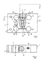
- the 1 and 2 consists of a cuboid steel spring element 1, which is provided at one end forming the bearing area 2 with two bores 3 for attachment to a housing and other abutment part.
- the spring element has four round through holes 4, 5 arranged at the corners of a square, which are directed perpendicular to the broad sides of the cuboid spring element.
- the two through holes 4 located on the side of the bearing area 2 are connected to one another by a narrow slot 6 forming a stop lug and each to their other, adjacent through hole 4 via parallel slots 7 and 8.
- the slots 6, 7, 8 delimit a tongue 9 which is rigidly connected to the end 10 of the spring element opposite the bearing area 2.
- the end 10 is connected to the bearing area 2 via the two outer deformation areas, so-called upper and lower chords.
- the upper deformation area 11 is provided with an enlarged bore through which a Screw is screwed into a threaded bore 13 in the force introduction area 14 lying between the two slots 6 and 7.
- This screw (not shown) can be used to introduce tensile or compressive forces F, the deformation of the regions 11 and 12 being detected by means of strain gauges 15 attached to the outside of the spring element.
- the slots 7 and 8 have a width of approximately 0.2 to 0.5 millimeters, so that, in the event of an overload, the tongue 9, depending on the tensile or compressive load, on the area near the storage area 2 the stop nose lying stops 17 or 18.
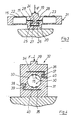
- the force application area 19 and the bearing area 20 of the spring element 21 lie directly behind one another in the direction of introduction of the force F.
- the areas 19, 20 are connected to one another via lateral deformation areas 22, 23 which carry the strain gauges 15.
- the force application area 19 has a lower, rigid tongue 24, the transverse legs 25, 26 of which are framed by U-shaped recesses in the bearing area 20, again a narrow gap of only one or a few tenths of a millimeter width being provided between the bearing area 20 and the force application area 19.
- the transverse legs 25, 26 of the tongue 24 strike the lower stop surface 27 and, in the event of a train overload, the upper stops 28 on the bearing part 20.
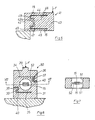
- the force introduction area 29, the deformation area 30 and the bearing area 31 are essentially at the rear in the direction of force application.
- the pickup here also consists of an essentially cuboidal spring element 32.
- a through hole 33 is provided, on the wall of which the strain gauges 15 are arranged.
- the regions 29, 30, 31 are each separated from one another by narrow slots 34, 35 which are open to opposite sides of the spring element 32 and which close to their mouths several times with the formation of L-shaped stop tongues 36, 37, 38 which engage behind each other in pairs. 39 are angled.
- the tongues 37, 39 belonging to the force introduction area 29 strike the stops associated with the tongues 36 and 38 belonging to the bearing area 31 in the event of a train overload, or hit the lower slot walls 40 provided in the bearing area 31 in the event of pressure overload.
- FIG. 5 illustrates a further embodiment of a pressure and tension sensor, in which the spring element 41 is designed as a projecting bending beam with a storage area 42 and a force application area 43 lying side by side.
- the force introduction region 43 is connected to the bearing region 42 via an upper deformation region 44 and a lower deformation region 45 and has a rigid tongue 46, which in turn is only accessible from the bearing region 42 and the deformation regions 44 and through a narrow, overall approximately U-shaped slot 47 45 is separated.
- the tongue 46 strikes the stops 48, 49 of the stop lug 42a, which here lie at the transition point between the bearing area 42 and the deformation area 44, 45.
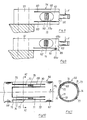
- FIG. 6 and 7 show a shear force transducer, in which the spring element 50, with the exception of the central blind bores 51, is identical to that of the tension and pressure transducer 4 is formed.
- the through hole 33 according to FIG. 4 two blind holes 51 lying opposite one another are provided here, between which a web 52 is left as the actual deformation element of the deformation region 53, on which strain gauges 15 are arranged on both sides.
- the overload protection here is the same as that in the exemplary embodiment according to FIG. 4.
- FIG. 8 illustrates a shear force transducer with a spring element 54 arranged in the manner of a bending beam, with a bearing area 55 and with a force introduction area 56 arranged at the freely projecting end.
- the force introduction area 56 or the deformation area 57 immediately following it, with the actual deformation element 57a, is here between the load direction two rigid tongues 58, 59 of the bearing area 54 bordered.
- the width of the slots 60 between the tongues 58, 59 and the deformation region 57 is again only a few tenths of a millimeter, so that the tongues 58, 59 form overload stops.
- the spring element 66 consists here of a tube which is provided between the moment introduction end 67 and the bearing end 68 with a plurality of parallel slots 69, 70, 71, 72, which narrow, the two ends 67, 68 delimiting connecting webs 73 and wider tongues 74 projecting from the moment introduction ends 67.
- the tongues 74 strike the root regions 75 of the deformation webs 73, which are still essentially rigid there, immediately adjacent to the bearing end 68.
Landscapes
- Physics & Mathematics (AREA)
- General Physics & Mathematics (AREA)
- Measuring Fluid Pressure (AREA)
- Measurement Of Force In General (AREA)
- Force Measurement Appropriate To Specific Purposes (AREA)
- Investigating Strength Of Materials By Application Of Mechanical Stress (AREA)
Abstract
Description
- Die Erfindung betrifft einen Kraft- oder Momentaufnehmer für Vorrichtungen zum Messen von Druck-, Zug-, Scherkräften oder Drehmomenten, welcher ein einstückiges, durch Schlitze unterteiltes Federelement mit Lagerbereich, mit Kraft- bzw. Momenteinleitungsbereich und mit Verformungsbereich aufweist, dem je ein in Lastrichtung und ein in Gegenrichtung wirksamer Anschlag zugeordnet ist.
- Bei den bekannten derartigen Aufnehmern (US-PS 31 35 112) ist das Federelement mit durch Bohren und Fräsen hergestellten Schlitzen versehen, die den Krafteinleitungsbereich, den Lagerbereich und den Verformungsbereich voneinander trennen. Fertigungstechnisch bedingt weisen die Schlitze bei den bekannten Aufnehmern eine Breite auf, die um ein Vielfaches größer als die Durchbiegung bei Nennlast ist. Bei einer Überlastung besteht dort die Gefahr einer plastischen Verformung des Federelementes und insbesondere die Gefahr einer Überanspruchung und dauerhaften Beschädigung der Dehnungsmeßstreifen und Biegezonen des Federelementes. Es ist bekannt, derartige Aufnehmer mit einer Überlastsicherung in Form von flächigen Anschlagstücken oder von Anschlagschrauben zu versehen, die in entsprechende Gewindebohrungen des Federelementes oder eines Gehäuses eingeschraubt und entsprechend der maximal zulässigen Überlast justiert werden. Solche Überlastsicherungen erfordern jedoch gesonderte Bauteile, was angesichts der hohen Präzisionsanforderungen einen großen technischen Aufwand bedingt.
- Der Erfindung liegt die Aufgabe zugrunde, die Herstellkosten und die Baugröße der gattungsgemäßen überlastgesicherten Aufnehmer zu verringern und Justierarbeiten zu erübrigen.
- Zur Lösung dieser Aufgabe ist erfindungsgemäß vorgesehen, daß der Lagerbereich und der Kraft- bzw. Momenteinleitungsbereich durch einen oder mehrere, im Erodierverfahren hergestellte Schlitze derart getrennt sind, daß sich an ener Stelle Schlitzwände als Uberlastanschlag und an einer anderen Stelle Schlitzwände als Gegenanschlag gegenüberliegen, und daß der Abstand der Schlitzwände im Bereich der Anschläge um etwa 10% größer als der Auslenkweg bei Nennlast ist. Die Schlitzbreite zwischen Zunge und Anschlagflächen liegt der Erfindung zufolge in der Größenordnung von 0,1 bis 0,5 Millimetern.
- Die Erfindung betrifft ferner ein Verfahren zur Herstellung solcher Aufnehmer. Das Verfahren ist erfindungsgemäß dadurch gekennzeichnet, daß die Schlitze im Federelement durch Erodieren ausgebildet werden.
- Durch Erodieren, d. h. durch funkenerosives Drahtschneiden, lassen sich in aus Stahl und allen aus elektrisch leitendem Material bestehenden Federelementen äußerst dünne Schlitze mit größter geometrischer Präzision herstellen.
- Die Erfindung erbringt eine Reihe von wesentlichen Vorteilen. Zum einen ist die Herstellung der Aufnehmer wesentlich verbilligt, da die Ausbildung der Schlitze durch Erodieren wesentlich preisgünstiger ausführbar ist als durch Bohren und Fräsen. Die engen Schlitze erlauben es in Verbindung mit der erfindungsgemäßen Formgebung der ineinandergreifenden Lager- und Krafteinleitungsbereiche, ihre Begrenzungswände unmittelbar als Überlast-Anschlagflächen auszunutzen. Hierdurch entfallen gesonderte Überlast-Anschlagelemente und werden kleine Bauformen ermöglicht Die Aufnehmer nach der Erfindung können reproduzierbar hergestellt werden und erlauben eine preiswerte Massenfertigung für einen Einsatz beispielsweise bei Wägeeinrichtungen.
- Weitere Merkmale und Ausgestaltungen der Erfindung sind in den Unteransprüchen angegeben.
- Die Erfindung wird im folgenden anhand mehrerer in der Zeichnung dargestellter Ausführungsbeispiele näher beschrieben. In der Zeichnung zeigen :
- Fig. 1 in Draufsicht einen Zug- und Druckaufnehmer nach der Erfindung,
- Fig. 2 eine Ansicht, teils geschnitten, gemäß der Linie II-II in Fig. 1,
- Fig. 3 in einem Querschnitt ein zweites Ausführungsbeispiel eines Zug- und Druckaufnehmers,
- Fig. 4 ein drittes Ausführungsbeispiel für einen Zug- und Druckaufnehmer,
- Fig. 5 ein weiteres Ausführungsbeispiel für einen Druck- und Zugaufnehmer,
- Fig 6. einen Scherkraftaufnehmer nach der Erfindung,
- Fig. 7 einen Schnitt gemäß der Linie VII-VII in Fig. 5,
- Fig. 8 und 9 zwei weitere Beispiele für einen Scherkraftaufnehmer nach der Erfindung,
- Fig.10 einen Momentaufnehmer nach der Erfindung und
- Fig.11 einen Schnitt gemäß der Linie XI-XI in Fig 10.
- Der Druck- und Zugaufnehmer nach den Fig. 1 und 2 besteht aus einem quaderförmigen Stahlfederelement 1, das an einem, den Lagerbereich 2 bildenden Ende mit zwei Bohrungen 3 zur Befestigung an einem Gehäuse und sonstigem Widerlagerteil versehen ist. Das Federelement weist vier, an den Ecken eines Quadrates angeordnete runde Durchgangslöcher 4, 5 auf, welche senkrecht zu den Breitseiten des quaderförmigen Federelementes gerichtet sind. Die beiden an der Seite des Lagerbereiches 2 liegenden Durchgangsbohrungen 4 sind miteinander durch einen schmalen, eine Anschlagnase bildenden Schlitz 6 und jeweils mit ihrer anderen, benachbarten Durchgangsbohrung 4 über parallele Schlitze 7 und 8 verbunden. Die Schlitze 6, 7, 8 begrenzen eine Zunge 9, die mit dem dem Lagerberech 2 gegenüberliegenden Ende 10 des Federelementes starr verbunden ist. Das Ende 10 ist über die beiden außenliegenden Verformungsbereiche, sogenannten Ober- und Untergurte, mit dem Lagerbereich 2 verbunden. Der obere Verformungsbereich 11 ist mit einer erweiterten Bohrung versehen, durch die hindurch eine Schraube in eine Gewindebohrung 13 in den zwischen den beiden Schlitzen 6 und 7 liegenden Krafteinleitungsbereich 14 eingeschraubt wird. Über diese Schraube (nicht gezeigt) können Zug- oder Druckkräfte F eingeleitet werden, wobei die Verformung der Bereiche 11 und 12 mittels außen an dem Federelement angebrachter Dehnungsmeßstreifen 15 erfaßt wird. Die Schlitze 7 und 8 weisen beim Ausführungsbeispiel nach den Fig. 1 und 2 eine Breite von etwa 0,2 bis 0,5 Millimetern auf, so daß bei einer Überbelastung die Zunge 9 je nach Zug- oder Druckbelastung auf die nahe beim Lagerbereich 2 an der Anschlagnase liegenden Anschläge 17 oder 18 auftrifft.
- Beim Zug- und Druckmesser nach Fig. 3 liegen Krafteinleitungsbereich 19 und Lagerbereich 20 des Federelementes 21 in Einleitungsrichtung der Kraft F unmittelbar hintereinander. Die Bereiche 19, 20 sind über seitliche Verformungsbereiche 22, 23 miteinander verbunden, welche die Dehnungsmeßstreifen 15 tragen. Der Krafteinleitungsbereich 19 weist eine untere, starre Zunge 24 auf, deren Querschenkel 25, 26 von U-förmigen Ausnehmungen des Lagerbereiches 20 eingefaßt sind, wobei wiederum ein schmaler Spalt von nur ein oder wenigen Zehntel Millimeter Breite zwischen Lagerbereich 20 und Krafteinleitungsbereich 19 vorgesehen ist. Bei Drucküberbelastung treffen die Querschenkel 25, 26 der Zunge 24 auf die untere Anschlagfläche 27 und bei Zugüberbelastung auf die oberen Anschläge 28 am Lagerteil 20 auf.
- Bei dem Ausführungsbeispiel nach Fig. 4 eines Zug- und Druckaufnehmers liegen Krafteinleitungsbereich 29, Verformungsbereich 30 und Lagerbereich 31 im wesentlichen in Krafteinleitungsrichtung hinterenander. Der Aufnehmer besteht auch hier aus einem im wesentlichen quaderförmigen Federelement 32. Im Verformungsbereich 30 ist eine Durchgangsbohrung 33 vorgesehen, an deren Wandung die Dehnungsmeßstreifen 15 angeordnet sind. Die Bereiche 29, 30, 31 sind jeweils durch schmale, zu entgegengesetzten Seiten des Federelementes 32 hin offene Schlitze 34, 35 voneinander getrennt, welche nahe ihrer Mündung mehrfach unter Bildung von L-förmigen, sich jeweils paarweise hintergreifenden Anschlagzungen 36, 37, 38, 39 abgewinkelt sind. Die dem Krafteinleitungsbereich 29 zugehörigen Zungen 37, 39 treffen bei Zug-Überbelastung als Anschläge auf die dem Lagerbereich 31 zugehörigen Zungen 36 und 38 auf, bzw treffen bei Druck-Überlastung auf die am Lagerbereich 31 vorgesehenen unteren Schlitzwände 40 auf.
- Fig. 5 veranschaulicht eine weitere Ausführungsform eines Druck- und Zugaufnehmers, bei dem das Federelement 41 als abragender Biegebalken mit seitlich nebeneinander liegendem Lagerbereich 42 und Krafteinleitungsbereich 43 ausgebildet ist. Der Krafteinleitungsbereich 43 ist über einen oberen Verformungsbereich 44 und einen unteren Verformungsbereich 45 mit dem Lagerbereich 42 verbunden und weist eine starre Zunge 46 auf, die wiederum nur durch einen schmalen, insgesamt etwa U-förmig verlaufenden Schlitz 47 vom Lagerbereich 42 und den Verformungsbereichen 44 und 45 getrennt ist. Bei Überlastung trifft die Zunge 46 auf die Anschläge 48, 49 der Anschlagnase 42a auf, die hier an der Übergangsstelle von Lagerbereich 42 und Verformungsbereich 44, 45 liegen.
- Die Fig. 6 und 7 zeigen einen Scherkraftaufnehmer, bei dem das Federelement 50 mit Ausnahme der mittigen Sacklochbohrungen 51 identisch wie bei dem Zug- und Druckaufnehmer nach Fig. 4 ausgebildet ist. Anstelle der Durchgangsbohrung 33 nach Fig. 4 sind hier zwei sich gegenüberliegende Sacklochbohrungen 51 vorgesehen, zwischen denen ein Steg 52 als eigentliches Verformungselement des Verformungsbereiches 53 belassen ist, auf dem beidseits Dehnungsmeßstreifen 15 angeordnet sind. Die Überlastsicherung ist hier gleich der beim Ausführungsbeispiel nach Fig 4.
- Fig. 8 veranschaulicht einen Scherkraftaufnehmer mit einem nach Art eines Biegebalkens angeordneten Federelement 54 mit Lagerbereich 55 und mit am frei abragenden Ende angeordnetem Krafteinleitungsbereich 56. Der Krafteinleitungsbereich 56 bzw. der sich unmittelbar daran anschließende Verformungsbereich 57 mit dem eigentlichen Verformungselement 57a ist hier in Belastungsrichtung zwischen zwei starren Zungen 58, 59 des Lagerbereiches 54 eingefaßt. Die Breite der Schlitze 60 zwischen den Zungen 58, 59 und dem Verformungsbereich 57 beträgt auch hier wiederum nur wenige Zehntel Millimeter, so daß die Zungen 58, 59 Überlastanschläge bilden.
- Beim Scherkraftaufnehmer nach Fig. 9 ragt vom Lagerbereich 61 nur eine Zunge 62 in Richtung des Krafteinleitungsteiles 63 ab, die hier mit einer Zungenspitze 64 in eine U-Nut 65 am Krafteinleitungsteil 63 hineinragt, so daß auch hier sowohl für Zug als auch für Druck jeweils ein ÜberlastAnschlag 65a, 65b gegeben ist.
- Die Fig. 10 und 11 veranschaulichen schließlich noch einen Drehmomentaufnehmer. Das Federelement 66 besteht hier aus einem Rohr, das zwischen dem Momenteinleitungsende 67 und dem Lagerende 68 mit mehreren parallelen Schlitzen 69, 70, 71, 72 versehen ist, welche schmale, die beiden Enden 67, 68 verbindende Verformungsstege 73 und von den Momenteinleitungsende 67 abragende breitere Zungen 74 begrenzen. Bei einer Überlastung durch zu großes Drehmoment Mt treffen die Zungen 74 unmittelbar angrenzend an das Lagerende 68 auf die dort noch im wesentlichen starren Wurzelbereiche 75 der Verformungsstege 73 auf.
Claims (7)
Priority Applications (1)
| Application Number | Priority Date | Filing Date | Title |
|---|---|---|---|
| AT87109065T ATE57767T1 (de) | 1986-06-26 | 1987-06-24 | Aufnehmer fuer vorrichtungen zum messen von druck- zug-, scherkraeften. |
Applications Claiming Priority (2)
| Application Number | Priority Date | Filing Date | Title |
|---|---|---|---|
| DE3621378 | 1986-06-26 | ||
| DE19863621378 DE3621378A1 (de) | 1986-06-26 | 1986-06-26 | Aufnehmer fuer vorrichtungen zum messen von druck-, zug-, scherkraeften oder drehmomenten und verfahren zu seiner herstellung |
Publications (3)
| Publication Number | Publication Date |
|---|---|
| EP0251175A2 true EP0251175A2 (de) | 1988-01-07 |
| EP0251175A3 EP0251175A3 (en) | 1989-10-04 |
| EP0251175B1 EP0251175B1 (de) | 1990-10-24 |
Family
ID=6303729
Family Applications (1)
| Application Number | Title | Priority Date | Filing Date |
|---|---|---|---|
| EP87109065A Expired - Lifetime EP0251175B1 (de) | 1986-06-26 | 1987-06-24 | Aufnehmer für Vorrichtungen zum Messen von Druck- Zug-, Scherkräften |
Country Status (3)
| Country | Link |
|---|---|
| EP (1) | EP0251175B1 (de) |
| AT (1) | ATE57767T1 (de) |
| DE (2) | DE3621378A1 (de) |
Cited By (12)
| Publication number | Priority date | Publication date | Assignee | Title |
|---|---|---|---|---|
| WO1997035169A1 (en) * | 1996-03-18 | 1997-09-25 | Nobel Elektronik Ab | Shear beam load cell |
| EP0978713A3 (de) * | 1998-08-03 | 2001-08-08 | Mannesmann VDO Aktiengesellschaft | Drehwinkelbegrenzung durch eine Trennfuge im Gehäuse eines Drehmomentsensors |
| US6755087B2 (en) * | 2001-11-26 | 2004-06-29 | Interface, Inc. | Load cell having overload protection |
| CN102980689A (zh) * | 2012-11-29 | 2013-03-20 | 昆山洺九机电有限公司 | 防过载荷重传感器 |
| EP2985578A1 (de) | 2014-08-15 | 2016-02-17 | Bizerba GmbH & Co. KG | Wägezelle zur gewichtskraftmessung |
| EP2977731A4 (de) * | 2013-03-18 | 2016-11-02 | Mettler Toledo Changzhou Prec Instr Ltd | Elastischer körper eines wägesensors |
| CN107209074A (zh) * | 2015-01-19 | 2017-09-26 | 帝国创新有限公司 | 力值测量装置 |
| CN109696229A (zh) * | 2017-10-24 | 2019-04-30 | 和仁机械电子株式会社 | 测压元件 |
| WO2020112017A1 (en) * | 2018-11-30 | 2020-06-04 | Väderstad Holding Ab | Force sensor, agricultural implement comprising such force sensor, method of operating such agricultural implement, method of measuring force and method of manufacturing a force sensor |
| EP3845874A1 (de) * | 2019-12-30 | 2021-07-07 | Bizerba SE & Co. KG | Regalkonsole |
| EP3845872A1 (de) * | 2019-12-30 | 2021-07-07 | Bizerba SE & Co. KG | Wägezelle |
| US11668599B2 (en) | 2019-12-30 | 2023-06-06 | Bizerba SE & Co. KG | Shelf bracket assembly |
Families Citing this family (3)
| Publication number | Priority date | Publication date | Assignee | Title |
|---|---|---|---|---|
| DE4009286C2 (de) * | 1990-03-22 | 2000-11-23 | Wiegand Gmbh & Co Alexander | Anordnung zum Messen der Torsion eines stabförmigen Hohlkörpers |
| DE4208522C2 (de) * | 1992-03-18 | 2000-08-10 | Hottinger Messtechnik Baldwin | Drehmomentsensor |
| US5319161A (en) † | 1992-12-24 | 1994-06-07 | Pitney Bowes Inc. | Mechanism for preventing overload on a weighing scale |
Family Cites Families (6)
| Publication number | Priority date | Publication date | Assignee | Title |
|---|---|---|---|---|
| US3135112A (en) * | 1960-09-06 | 1964-06-02 | Baldwin Lima Hamilton Corp | Safety-load control of parallelogram type of load cell |
| US4166998A (en) * | 1977-06-22 | 1979-09-04 | Gould Inc., Statham Instrument Division | Force transducer |
| US4338825A (en) * | 1980-10-15 | 1982-07-13 | Eaton Corporation | Strain gage load cell |
| DE3336727C2 (de) * | 1983-10-08 | 1985-09-12 | Erhardt & Leimer GmbH, 8900 Augsburg | Vorrichtung zur Linearkraftmessung |
| HU189359B (en) * | 1983-11-11 | 1986-06-30 | Magyar Optikai Muevek,Hu | Complex meassuring device for high-accuracy strain gauge force meters |
| DD226649A1 (de) * | 1984-09-18 | 1985-08-28 | Robotron Messelekt | Anordnung fuer eine in eine kraftmesseinrichtung integrierte ueberlastsicherung |
-
1986
- 1986-06-26 DE DE19863621378 patent/DE3621378A1/de active Granted
-
1987
- 1987-06-24 AT AT87109065T patent/ATE57767T1/de not_active IP Right Cessation
- 1987-06-24 EP EP87109065A patent/EP0251175B1/de not_active Expired - Lifetime
- 1987-06-24 DE DE8787109065T patent/DE3765706D1/de not_active Expired - Fee Related
Cited By (18)
| Publication number | Priority date | Publication date | Assignee | Title |
|---|---|---|---|---|
| US6143993A (en) * | 1996-03-18 | 2000-11-07 | Nobel Elekronik Ab | Shear beam load cell |
| WO1997035169A1 (en) * | 1996-03-18 | 1997-09-25 | Nobel Elektronik Ab | Shear beam load cell |
| EP0978713A3 (de) * | 1998-08-03 | 2001-08-08 | Mannesmann VDO Aktiengesellschaft | Drehwinkelbegrenzung durch eine Trennfuge im Gehäuse eines Drehmomentsensors |
| US6755087B2 (en) * | 2001-11-26 | 2004-06-29 | Interface, Inc. | Load cell having overload protection |
| CN102980689A (zh) * | 2012-11-29 | 2013-03-20 | 昆山洺九机电有限公司 | 防过载荷重传感器 |
| EP2977731A4 (de) * | 2013-03-18 | 2016-11-02 | Mettler Toledo Changzhou Prec Instr Ltd | Elastischer körper eines wägesensors |
| US9726559B2 (en) | 2014-08-15 | 2017-08-08 | Bizerba SE & Co. KG | Load cell for weight measurement |
| DE102014111682A1 (de) | 2014-08-15 | 2016-02-18 | Bizerba Gmbh & Co Kg | Wägezelle zur Gewichtskraftmessung |
| EP2985578A1 (de) | 2014-08-15 | 2016-02-17 | Bizerba GmbH & Co. KG | Wägezelle zur gewichtskraftmessung |
| CN107209074A (zh) * | 2015-01-19 | 2017-09-26 | 帝国创新有限公司 | 力值测量装置 |
| CN107209074B (zh) * | 2015-01-19 | 2020-02-11 | Ip2Ipo革新有限公司 | 力值测量机构 |
| CN109696229A (zh) * | 2017-10-24 | 2019-04-30 | 和仁机械电子株式会社 | 测压元件 |
| WO2020112017A1 (en) * | 2018-11-30 | 2020-06-04 | Väderstad Holding Ab | Force sensor, agricultural implement comprising such force sensor, method of operating such agricultural implement, method of measuring force and method of manufacturing a force sensor |
| EP3845874A1 (de) * | 2019-12-30 | 2021-07-07 | Bizerba SE & Co. KG | Regalkonsole |
| EP3845872A1 (de) * | 2019-12-30 | 2021-07-07 | Bizerba SE & Co. KG | Wägezelle |
| US11609132B2 (en) | 2019-12-30 | 2023-03-21 | Bizerba SE & Co. KG | Load cell |
| US11607059B2 (en) | 2019-12-30 | 2023-03-21 | Bizerba SE & Co. KG | Shelf bracket assembly |
| US11668599B2 (en) | 2019-12-30 | 2023-06-06 | Bizerba SE & Co. KG | Shelf bracket assembly |
Also Published As
| Publication number | Publication date |
|---|---|
| EP0251175A3 (en) | 1989-10-04 |
| DE3621378A1 (de) | 1988-01-14 |
| DE3765706D1 (de) | 1990-11-29 |
| DE3621378C2 (de) | 1988-05-05 |
| EP0251175B1 (de) | 1990-10-24 |
| ATE57767T1 (de) | 1990-11-15 |
Similar Documents
| Publication | Publication Date | Title |
|---|---|---|
| EP0251175A2 (de) | Aufnehmer für Vorrichtungen zum Messen von Druck- Zug-, Scherkräften | |
| EP0518202B1 (de) | Vorrichtung zur Kraftuntersetzung in einer Kraftmesseinrichtung, insbesondere einer Waage | |
| DE3232817C1 (de) | Biegefeder | |
| EP2985578B1 (de) | Wägezelle zur gewichtskraftmessung | |
| DE69203140T2 (de) | Verschiebungsverstärkungsmechanismus mit piezoelektrisches Element. | |
| EP0080702A2 (de) | Kraftmessvorrichtung | |
| DE69213506T2 (de) | Kraftaufnehmer | |
| EP2356416B1 (de) | Kraftmessplatte | |
| DE2117477B2 (de) | Kraftmeßwertwandler | |
| EP1754030B1 (de) | Überlastsicherung für ein kraftmesselement | |
| DE10224199A1 (de) | Kraft-Messdose | |
| DE1447995C3 (de) | Elektromechanischer Wandler mit einem Piezo-Widerstandselement | |
| EP0310758A2 (de) | Elektromechanische Waage | |
| WO2003029765A1 (de) | Dünnstellen-biegelager für eine kraftmesseinrichtung und vorrichtung zur kraftübertragung mit einem solchen | |
| EP1530035B1 (de) | Kraftmesszelle mit Befestigungsentkopplung durch vorstehende Flächen und kurze Einschnitte | |
| DE3438498C2 (de) | ||
| DE3427573A1 (de) | Kraftaufnehmer | |
| CH353555A (de) | Kraftmesseinrichtung | |
| EP0719405A1 (de) | Kraftmessvorrichtung | |
| DE3619616C2 (de) | Präzisionswaage | |
| DE3119806C2 (de) | ||
| DE2129214A1 (de) | Messwertwandler, insbesondere fuer die kraftmessung | |
| DE2917966A1 (de) | Einrichtung zur messung von kraftkomponenten in gelenken | |
| DE8617017U1 (de) | Kraft- oder Momentaufnehmer für Vorrichtungen zum Messen von Druck-, Zug-, Scherkräften oder Drehmomenten | |
| EP2402730A1 (de) | Kraftaufnehmer mit Biegebalken mit kontinuierlicher Verjüngung |
Legal Events
| Date | Code | Title | Description |
|---|---|---|---|
| PUAI | Public reference made under article 153(3) epc to a published international application that has entered the european phase |
Free format text: ORIGINAL CODE: 0009012 |
|
| AK | Designated contracting states |
Kind code of ref document: A2 Designated state(s): AT BE CH DE ES FR GB IT LI NL SE |
|
| PUAL | Search report despatched |
Free format text: ORIGINAL CODE: 0009013 |
|
| AK | Designated contracting states |
Kind code of ref document: A3 Designated state(s): AT BE CH DE ES FR GB IT LI NL SE |
|
| 17P | Request for examination filed |
Effective date: 19891004 |
|
| 17Q | First examination report despatched |
Effective date: 19891121 |
|
| RAP3 | Party data changed (applicant data changed or rights of an application transferred) |
Owner name: A. M. ERICHSEN GMBH |
|
| GRAA | (expected) grant |
Free format text: ORIGINAL CODE: 0009210 |
|
| AK | Designated contracting states |
Kind code of ref document: B1 Designated state(s): AT BE CH DE ES FR GB IT LI NL SE |
|
| PG25 | Lapsed in a contracting state [announced via postgrant information from national office to epo] |
Ref country code: IT Free format text: LAPSE BECAUSE OF FAILURE TO SUBMIT A TRANSLATION OF THE DESCRIPTION OR TO PAY THE FEE WITHIN THE PRE;WARNING: LAPSES OF ITALIAN PATENTS WITH EFFECTIVE DATE BEFORE 2007 MAY HAVE OCCURRED AT ANY TIME BEFORE 2007. THE CORRECT EFFECTIVE DATE MAY BE DIFFERENT FROM THE ONE RECORDED.SCRIBED TIME-LIMIT Effective date: 19901024 Ref country code: SE Effective date: 19901024 Ref country code: BE Effective date: 19901024 Ref country code: NL Effective date: 19901024 Ref country code: GB Effective date: 19901024 Ref country code: FR Effective date: 19901024 |
|
| REF | Corresponds to: |
Ref document number: 57767 Country of ref document: AT Date of ref document: 19901115 Kind code of ref document: T |
|
| REF | Corresponds to: |
Ref document number: 3765706 Country of ref document: DE Date of ref document: 19901129 |
|
| PG25 | Lapsed in a contracting state [announced via postgrant information from national office to epo] |
Ref country code: ES Free format text: LAPSE BECAUSE OF FAILURE TO SUBMIT A TRANSLATION OF THE DESCRIPTION OR TO PAY THE FEE WITHIN THE PRESCRIBED TIME-LIMIT Effective date: 19910204 |
|
| EN | Fr: translation not filed | ||
| NLV1 | Nl: lapsed or annulled due to failure to fulfill the requirements of art. 29p and 29m of the patents act | ||
| GBV | Gb: ep patent (uk) treated as always having been void in accordance with gb section 77(7)/1977 [no translation filed] | ||
| PG25 | Lapsed in a contracting state [announced via postgrant information from national office to epo] |
Ref country code: AT Effective date: 19910624 |
|
| PG25 | Lapsed in a contracting state [announced via postgrant information from national office to epo] |
Ref country code: LI Effective date: 19910630 Ref country code: CH Effective date: 19910630 |
|
| PLBE | No opposition filed within time limit |
Free format text: ORIGINAL CODE: 0009261 |
|
| STAA | Information on the status of an ep patent application or granted ep patent |
Free format text: STATUS: NO OPPOSITION FILED WITHIN TIME LIMIT |
|
| 26N | No opposition filed | ||
| REG | Reference to a national code |
Ref country code: CH Ref legal event code: PL |
|
| PGFP | Annual fee paid to national office [announced via postgrant information from national office to epo] |
Ref country code: DE Payment date: 19990212 Year of fee payment: 12 |
|
| PG25 | Lapsed in a contracting state [announced via postgrant information from national office to epo] |
Ref country code: DE Free format text: LAPSE BECAUSE OF NON-PAYMENT OF DUE FEES Effective date: 20000503 |