EP0249901A2 - Selbsteinfärbender Gummistempel - Google Patents
Selbsteinfärbender Gummistempel Download PDFInfo
- Publication number
- EP0249901A2 EP0249901A2 EP87108499A EP87108499A EP0249901A2 EP 0249901 A2 EP0249901 A2 EP 0249901A2 EP 87108499 A EP87108499 A EP 87108499A EP 87108499 A EP87108499 A EP 87108499A EP 0249901 A2 EP0249901 A2 EP 0249901A2
- Authority
- EP
- European Patent Office
- Prior art keywords
- housing
- plate
- ink pad
- stamp
- rubber
- Prior art date
- Legal status (The legal status is an assumption and is not a legal conclusion. Google has not performed a legal analysis and makes no representation as to the accuracy of the status listed.)
- Withdrawn
Links
Images

Classifications
-
- B—PERFORMING OPERATIONS; TRANSPORTING
- B41—PRINTING; LINING MACHINES; TYPEWRITERS; STAMPS
- B41K—STAMPS; STAMPING OR NUMBERING APPARATUS OR DEVICES
- B41K1/00—Portable hand-operated devices without means for supporting or locating the articles to be stamped, i.e. hand stamps; Inking devices or other accessories therefor
- B41K1/36—Details
- B41K1/38—Inking devices; Stamping surfaces
- B41K1/40—Inking devices operated by stamping movement
Definitions
- the present invention relates to self-inking rubber stamping devices.
- Conventional self-inking or automatic stamps generally comprise a two-part housing, a solid-rubber printing stamp glued to a pivoted, displaceable base plate, and an ink-absorbent pad made of cellular rubber or felt. With light vertical pressure on the upper part of the housing, while the lower part is placed on a paper sheet, a stamping process is performed whereby the stamp, which contacts the ink pad, slides downwards, turns over into an upside-down position, and becomes pressed against the paper.
- the construction was such that the rubber stamp was in constant compressive contact with the ink pad. This continuous pressure on the ink pad caused excessive deformation of the pad which, of course, reduced its efficiency to ink the rubber molded characters of the stamp. If, on the other hand, a more rigid sponge were used as an ink pad, in order to better withstand the prolonged pressure, a print of poor quality would result.
- a self-inking rubber stamping device comprising a housing having opposite side walls and an open bottom adapted to be placed over a surface to be stamped, and an ink pad fixedly mounted within the housing.
- a manipulable member having a top wall and opposite side walls is provided, which is coupled to and moveable with respect to the housing and includes a pivotable, as well as displaceable, rubber stamp plate.
- the pivotal displacement of the stamp plate by the manipulable member is effected by an overturning mechanism, between an inoperative position, wherein the plate is withdrawn into the housing and the rubber stamp faces the ink pad, and an operative position, wherein the stamp plate is pivoted and displaced to become pressed against the said surface through the bottom of the housing.
- the ink pad is positioned at right-angles to and above the bottom of the housing.
- the stamp plate is moveable parallel to the ink pad, as well as rotatable about a first axis fixed relative to the housing, and is coupled to the manipulable member by an axle defining a second axis spaced from, and extending parallel to, the first axis.
- the axle is moveable along a curved path defined by the composite movement of first guide-slots formed in the opposite side walls of the housing and second guide-slots formed in the opposite side walls of the manipulable member through which the axle is passed, to bring the rubber stamp face-down against the said surface.
- the plate may be provided with a pair of rearward extending U-shaped bars, and the side walls of the housing are each provided with a projection in axial alignment with one another along the said first axis, each projection supporting one of the bars during the parallel and the rotatable movement of the plate.
- the guide-slots of either the manipulable member or the housing member are configured so that in the inoperative position, the rubber stamp is spaced from the ink pad, and the movement of the plate is commenced by the plate approaching the pad, which movement effects the wetting of the rubber stamp by the pad.
- the manipulable member may be either hinged or slidingly mounted on the housing member.
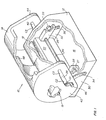
- the stamping device 10 in Fig. 1 comprises a stationary housing member 12 and a manipulable member 14, hinged to the housing member 12 by pins 15 (only one being shown in Fig. 1).
- the housing 12 has an open bottom 16.
- Ink pad 18 is accommodated within the housing 12 against a rear wall 20 (Fig. 2b), means being provided (not shown) for the removal of the pad in case it needs replacement.
- a rubber stamp plate 22 with rubber stamp 24 attached thereto is accommodated within the housing 12, within the housing 12, is accommodated a rubber stamp plate 22 with rubber stamp 24 attached thereto.
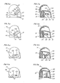
- the plate 22 and the ink pad 18 face each other, both being vertically positioned -- in contradistinction to conventional devices where the pad and the stamp were horizontally positioned, the pad facing down and the stamp facing up thereagainst.
- the plate 22 is extended rearward by a pair of U-shaped bars 25, 26, both facing outward to serve as guide-slots operatively associated with a pair of inward directed pins 27 and 28, respectively.
- the pin 27 is formed integrally with side wall 30 of the housing 12, and the pin 28 is formed integrally with side wall 32.
- the pins 27 and 28 may be attached separately to the housing walls 30 and 32, respectively; or, the guide-slots, constituted by the bars 25, 26, may be associated with walls 30, 32 and pins 27, 28 formed as part of the stamp plate 22 -- all at the designer's option.
- the side walls 30 and 32 of the housing 12 are each provided with an arcuate, downward-sloping guide-slot, designated 34 and 36, respectively.
- Generally upward-sloping guide-slots 38 and 40 are formed in side walls 42 and 44 of the manipulable member 14.
- the slots 38 and 40 comprise a convex cam surface or portion C1, a substantially straight cam portion C2 and a slightly tapering cam portion C3.
- a cross rod 46 is passed (in the following order) through slots 38 and 34, bars 25 and 26, and slots 36 and 40. The rod is free to move within the guide-slots while it is being fixedly held (by friction) by the bars 25, 26.
- a leaf-spring 48 is provided urging the member 14 away from the housing 12.
- the stamp plate 22 is kept a small distance apart from the ink pad 18. As stated above, this will assure prolonged useful life of the ink pad sponge material.
- the stamp plate Upon the initial downward movement of the member 14 (Figs. 3a-3b), the stamp plate will advance to the left against the ink pad and become wetted. This progressive sidewise movement of the plate is effected by the cam portion(s) C1 of the slots 38, 40, and enabled by the upper left-hand side(s) of the slots 34 and 36 (only partly shown in the Figures).
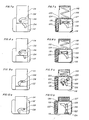
- the device 110 comprises a stationary housing member 112 and a manipulable member 114.
- Back wall 120 of the housing 112 is formed as a receptacle for the rubber sponge ink pad 118 (see Fig. 7b).
- Movement of the member 114 against the housing 112 is, in this case, linear, and suitable guide means are provided (not shown) for reciprocal sliding movement against one or two coil springs 148.
- rubber stamp plate 122 is provided in a vertical position facing the ink pad 118.
- the plate 122 is rotatably as well as displaceably mounted within the housing 112 by the same guide-slots arrangement, as shown, and need not be described again.
- Cross bar 146 extends through guide-slots 134, 136 of the housing side walls 130, 132, and slots 138, 140 in the respective side walls of the member 114, the arrangement being such that by pressing the member 114 downwards, the stamp plate performs the series of movements illustrated in Figs. 8b-10b.
- the curvatures of the slots are merely a result of design considerations.
- the guide-slots are configured so as to keep the stamp plate away from the ink pad at the initial, inoperative position, bring the rubber stamp 124 into momentary contact with the ink pad, and proceed downwards by a 90-degree rotation in a counterclockwise direction.
- the device according to the invention presents outstanding and unique advantages over conventional automatic rubber stamps. It is comprised of only a small number of parts, and compactly arranged, resulting in a conveniently operable, pocket-size article. It is further submitted that it is mainly the overall design features of the device, as afore-described, which enable the maintenance of the rubber stamp away from the ink pad during non-use of the device, in such a simple and straightforward manner.
Landscapes
- Manufacture Or Reproduction Of Printing Formes (AREA)
- Printing Methods (AREA)
- Printing Plates And Materials Therefor (AREA)
- Inking, Control Or Cleaning Of Printing Machines (AREA)
Applications Claiming Priority (2)
| Application Number | Priority Date | Filing Date | Title |
|---|---|---|---|
| IL79158 | 1986-06-19 | ||
| IL79158A IL79158A0 (en) | 1986-06-19 | 1986-06-19 | Self-inking rubber stamps |
Publications (2)
| Publication Number | Publication Date |
|---|---|
| EP0249901A2 true EP0249901A2 (de) | 1987-12-23 |
| EP0249901A3 EP0249901A3 (de) | 1988-08-24 |
Family
ID=11056871
Family Applications (1)
| Application Number | Title | Priority Date | Filing Date |
|---|---|---|---|
| EP87108499A Withdrawn EP0249901A3 (de) | 1986-06-19 | 1987-06-12 | Selbsteinfärbender Gummistempel |
Country Status (9)
| Country | Link |
|---|---|
| US (1) | US4805529A (de) |
| EP (1) | EP0249901A3 (de) |
| JP (1) | JPS62299377A (de) |
| KR (1) | KR920008499B1 (de) |
| AU (1) | AU7344287A (de) |
| BR (1) | BR8703054A (de) |
| DK (1) | DK301387A (de) |
| IL (1) | IL79158A0 (de) |
| ZA (1) | ZA873764B (de) |
Cited By (1)
| Publication number | Priority date | Publication date | Assignee | Title |
|---|---|---|---|---|
| WO2012159728A2 (de) | 2011-05-24 | 2012-11-29 | Trodat Gmbh | Stempel und zugehöriges stempelkissen |
Families Citing this family (13)
| Publication number | Priority date | Publication date | Assignee | Title |
|---|---|---|---|---|
| DE3512818A1 (de) * | 1985-04-10 | 1986-10-30 | Henkel KGaA, 4000 Düsseldorf | Verwendung eines handstempels mit umkehrbarem stempelkoerper zum klebstoffauftrag und entsprechend ausgebildeter handstempel |
| USD323527S (en) | 1990-01-09 | 1992-01-28 | Porelon, Inc. | Self-inking hand stamp |
| CA2013876C (en) * | 1990-04-04 | 1993-08-24 | Cameron Fink | Inker marker |
| US5359932A (en) * | 1992-09-21 | 1994-11-01 | Louis Melind Co. | Self-inking hand stamper with tilted inking pad |
| US5293818A (en) * | 1993-05-06 | 1994-03-15 | Mandzuk Raymond A | Transfer device, such as a printer device |
| US5435244A (en) * | 1993-08-20 | 1995-07-25 | Tooling Research, Inc. | High speed printing apparatus |
| US5669303A (en) * | 1996-03-04 | 1997-09-23 | Motorola | Apparatus and method for stamping a surface |
| AT407858B (de) * | 1998-11-11 | 2001-07-25 | Trodat Gmbh | Handstempel |
| JP2002273996A (ja) * | 2001-03-21 | 2002-09-25 | Yamahachi Chemical Co Ltd | 複数の印面を有する液浸透式スタンプ |
| US20030131818A1 (en) * | 2002-01-16 | 2003-07-17 | Kyle Gregoire | Intake manifold paddle system |
| BRPI0608111A2 (pt) * | 2005-02-28 | 2009-11-03 | Premd Inc | método e aparelho para a medição não-invasiva do colesterol no tecido da pele |
| US20080250956A1 (en) * | 2007-04-13 | 2008-10-16 | Elmer's Products, Inc. | Marking system |
| US8181310B2 (en) * | 2010-02-12 | 2012-05-22 | Fredman Bros. Furniture Company, Inc. | Caster brake assembly |
Family Cites Families (9)
| Publication number | Priority date | Publication date | Assignee | Title |
|---|---|---|---|---|
| US10740A (en) * | 1854-04-04 | Stephen hedges | ||
| US1142240A (en) * | 1912-11-11 | 1915-06-08 | William H Dodson | Hand-stamp. |
| FR509864A (fr) * | 1919-05-20 | 1920-11-22 | Georges Klein | Timbre à encrage automatique |
| US2312727A (en) * | 1940-12-06 | 1943-03-02 | Kent Hardware Mfg Corp | Stamping device |
| DE1276662B (de) * | 1960-05-04 | 1968-09-05 | Hans Schnaeckel G M B H | Selbstfaerbestempel |
| AT232014B (de) * | 1960-05-04 | 1964-02-25 | Hans Schnaeckel G M B H | Selbstfärbestempel |
| US3307479A (en) * | 1964-05-13 | 1967-03-07 | Roto American Corp | Imprinting device movable between inking and printing positions |
| FR2506219B1 (fr) * | 1981-05-25 | 1986-05-16 | Terseram Megras Ste Nle | Support de timbre, a encrage, ou auto-encre |
| US4432281A (en) * | 1982-03-10 | 1984-02-21 | M & R Seal Press Co., Inc. | Self-inking stamping device |
-
1986
- 1986-06-19 IL IL79158A patent/IL79158A0/xx not_active IP Right Cessation
-
1987
- 1987-05-26 ZA ZA873764A patent/ZA873764B/xx unknown
- 1987-05-27 AU AU73442/87A patent/AU7344287A/en not_active Abandoned
- 1987-06-09 US US07/059,944 patent/US4805529A/en not_active Expired - Fee Related
- 1987-06-12 EP EP87108499A patent/EP0249901A3/de not_active Withdrawn
- 1987-06-12 DK DK301387A patent/DK301387A/da not_active Application Discontinuation
- 1987-06-17 KR KR1019870006142A patent/KR920008499B1/ko not_active Expired
- 1987-06-18 BR BR8703054A patent/BR8703054A/pt unknown
- 1987-06-19 JP JP62151556A patent/JPS62299377A/ja active Pending
Cited By (8)
| Publication number | Priority date | Publication date | Assignee | Title |
|---|---|---|---|---|
| WO2012159728A2 (de) | 2011-05-24 | 2012-11-29 | Trodat Gmbh | Stempel und zugehöriges stempelkissen |
| AT511453B1 (de) * | 2011-05-24 | 2012-12-15 | Trodat Gmbh | Stempel und zugehöriges stempelkissen |
| AT511453A4 (de) * | 2011-05-24 | 2012-12-15 | Trodat Gmbh | Stempel und zugehöriges stempelkissen |
| WO2012159728A3 (de) * | 2011-05-24 | 2013-03-07 | Trodat Gmbh | Stempel und zugehöriges stempelkissen |
| RU2562044C2 (ru) * | 2011-05-24 | 2015-09-10 | Тродат Гмбх | Штемпель и относящаяся к нему штемпельная подушка |
| US9211754B2 (en) | 2011-05-24 | 2015-12-15 | Trodat Gmbh | Stamp and associated stamp pad |
| EP3067213A1 (de) | 2011-05-24 | 2016-09-14 | Trodat GmbH | Stempelkissen |
| US11135864B2 (en) | 2011-05-24 | 2021-10-05 | Trodat Gmbh | Stamp and associated stamp pad |
Also Published As
| Publication number | Publication date |
|---|---|
| DK301387A (da) | 1987-12-20 |
| US4805529A (en) | 1989-02-21 |
| IL79158A0 (en) | 1986-09-30 |
| BR8703054A (pt) | 1988-03-08 |
| EP0249901A3 (de) | 1988-08-24 |
| ZA873764B (de) | 1987-11-23 |
| KR880000243A (ko) | 1988-03-24 |
| DK301387D0 (da) | 1987-06-12 |
| AU7344287A (en) | 1987-12-24 |
| KR920008499B1 (ko) | 1992-09-30 |
| JPS62299377A (ja) | 1987-12-26 |
Similar Documents
| Publication | Publication Date | Title |
|---|---|---|
| US4805529A (en) | Self-inking rubber stamps | |
| EP0361826B1 (de) | Halterung eines Thermo-Druckkopfes und Thermo-Druckverfahren | |
| US4574693A (en) | Seal press | |
| US5359932A (en) | Self-inking hand stamper with tilted inking pad | |
| US3783786A (en) | Self-inking hand stamp | |
| KR970000597A (ko) | 잉크롤러장치와 잉크롤러장치를 구비한 넘버링머신 | |
| US4013007A (en) | Self-inking hand stamp | |
| US10946691B2 (en) | Embosser including rollers | |
| US5740737A (en) | Handstamping apparatus | |
| US4408950A (en) | Press loader | |
| JPS6119018Y2 (de) | ||
| US3221653A (en) | Open throat bed and cylinder imprinting machine | |
| US5165810A (en) | Portable printing apparatus | |
| JPS59230Y2 (ja) | インプリント装置 | |
| JPH047976Y2 (de) | ||
| CN219132431U (zh) | 一种写真机的卷材自动裁切装置 | |
| CN221875880U (zh) | 一种印刷机的纸张平整装置 | |
| CN215204100U (zh) | 一种提高电池配组率的打工号装置 | |
| KR900007575Y1 (ko) | 테이블이 이송되는 임프린터의 압지장치 | |
| BE1004736A3 (nl) | Tampondrukmachine en daarvoor bestemde inktverdeelinrichting. | |
| US4419171A (en) | Portable labeling machine | |
| US5890427A (en) | Stamping part of a stamp | |
| KR900007574Y1 (ko) | 테이블이 이송되는 임프린터 | |
| JPS6220294Y2 (de) | ||
| CA1084772A (en) | Inking mechanism for printing apparatus |
Legal Events
| Date | Code | Title | Description |
|---|---|---|---|
| PUAI | Public reference made under article 153(3) epc to a published international application that has entered the european phase |
Free format text: ORIGINAL CODE: 0009012 |
|
| 17P | Request for examination filed |
Effective date: 19870612 |
|
| AK | Designated contracting states |
Kind code of ref document: A2 Designated state(s): AT BE CH DE ES FR GB GR IT LI LU NL SE |
|
| PUAL | Search report despatched |
Free format text: ORIGINAL CODE: 0009013 |
|
| AK | Designated contracting states |
Kind code of ref document: A3 Designated state(s): AT BE CH DE ES FR GB GR IT LI LU NL SE |
|
| STAA | Information on the status of an ep patent application or granted ep patent |
Free format text: STATUS: THE APPLICATION HAS BEEN WITHDRAWN |
|
| 18W | Application withdrawn |
Withdrawal date: 19881003 |