EP0249868B1 - Füllmaschine und Füllverfahren für Säcke mit elastischen Komplementärverschlussstreifen - Google Patents
Füllmaschine und Füllverfahren für Säcke mit elastischen Komplementärverschlussstreifen Download PDFInfo
- Publication number
- EP0249868B1 EP0249868B1 EP87108373A EP87108373A EP0249868B1 EP 0249868 B1 EP0249868 B1 EP 0249868B1 EP 87108373 A EP87108373 A EP 87108373A EP 87108373 A EP87108373 A EP 87108373A EP 0249868 B1 EP0249868 B1 EP 0249868B1
- Authority
- EP
- European Patent Office
- Prior art keywords
- bag
- bags
- chain
- zipper
- filled
- Prior art date
- Legal status (The legal status is an assumption and is not a legal conclusion. Google has not performed a legal analysis and makes no representation as to the accuracy of the status listed.)
- Expired - Lifetime
Links
- 238000000034 method Methods 0.000 title claims description 10
- 230000008569 process Effects 0.000 title description 3
- 210000000080 chela (arthropods) Anatomy 0.000 claims description 31
- 238000000926 separation method Methods 0.000 claims description 17
- 230000009471 action Effects 0.000 claims description 9
- 230000005540 biological transmission Effects 0.000 claims description 8
- 230000000694 effects Effects 0.000 claims description 5
- 238000003892 spreading Methods 0.000 claims description 5
- 230000007480 spreading Effects 0.000 claims description 5
- 238000005520 cutting process Methods 0.000 claims description 3
- 238000004519 manufacturing process Methods 0.000 description 11
- 230000007246 mechanism Effects 0.000 description 8
- 238000004806 packaging method and process Methods 0.000 description 4
- 230000000994 depressogenic effect Effects 0.000 description 2
- 238000010276 construction Methods 0.000 description 1
- 238000007599 discharging Methods 0.000 description 1
- 230000005484 gravity Effects 0.000 description 1
- 238000012986 modification Methods 0.000 description 1
- 230000004048 modification Effects 0.000 description 1
- 238000002360 preparation method Methods 0.000 description 1
- 125000006850 spacer group Chemical group 0.000 description 1
- 238000011144 upstream manufacturing Methods 0.000 description 1
- 238000003466 welding Methods 0.000 description 1
Images

Classifications
-
- B—PERFORMING OPERATIONS; TRANSPORTING
- B65—CONVEYING; PACKING; STORING; HANDLING THIN OR FILAMENTARY MATERIAL
- B65B—MACHINES, APPARATUS OR DEVICES FOR, OR METHODS OF, PACKAGING ARTICLES OR MATERIALS; UNPACKING
- B65B43/00—Forming, feeding, opening or setting-up containers or receptacles in association with packaging
- B65B43/12—Feeding flexible bags or carton blanks in flat or collapsed state; Feeding flat bags connected to form a series or chain
- B65B43/123—Feeding flat bags connected to form a series or chain
Definitions
- the invention relates to a system by which a chain of interconnected reclosable plastic bags equipped with interlocking fastener strip rib and groove profiles ("zippers") are individually opened, filled, closed, and separated from the chain for packaging.
- zippers interlocking fastener strip rib and groove profiles
- a zipper lock plastic bag of the type described, for example, in U.S. Patent 3,198,228 has closed bottom and side edges and a reclosable upper end mouth with interlocking fastener strip rib and groove profiles running across inner facing surfaces of the mouth.
- the nature of manufacture and operation of the reclosable plastic bags presents altogether different handling problems than those presented by bags arranged for heat seal closing.
- reclosable zipper lock bags are typically closed at their mouth ends during the manufacture process in order to allow for proper interfitting of the rib and groove members and exit the manufacturing site in that closed condition. The bag mouths must be opened at a loading site to permit filling and then closed again for packaging.
- the present invention concerns a method and means for filling zipper lock plastic bags which directly satisfies the cost, production, and operational requirements of the low or intermittent production packager and affords reliability and convenience, making rapid filling of zipper lock plastic bags readily available to this type of packager.
- a system which can be manually operated, such as by hand or foot treadle lever, or automated, serves to open (for filling), close and separately discharge reclosable zipper lock plastic bags sequentially one at a time as the bags are conducted through the system laterally connected together with one another in a chain.
- the bags are top fillable and of a construction wherein each bag has closed bottom and side edges and reclosable zipper profiles extending across the top of each bag with upstanding front and rear pull flanges extending above the zipper profiles.
- the bags are partially separated by separations closing their adjacent sides, the separations extending upwardly past the zipper profiles to the tops of the pull flanges.
- Respective continuous strips integrally connect the tops of the front and rear pull flanges of all of the bags and thereby connect the bags in continuous series in a chain.
- the connecting strips have interior-facing (or exterior-facing) guide ribs extending continuously along their upper edge portions such that the bags can be slideably drawn through the system on guide rail supports.
- the strips are removable from the tops of the pull flanges so that the bags become separated from one another after being filled.
- the bags may enter the system with their mouth ends closed in the fashion they typically leave manufacture.
- Each bag is initially supported in a filling station between a pair of laterally directed arms substantially coaxial with the zipper profiles and guide ribs of the bags in the chain.
- Each arm has a guide rail for receiving thereacross the guide rib of one connecting strip such that the bag is supported on the arm; and each arm has a self-adjusting paddle which descends into the space between the respective pull flanges of the bag.
- the arms pivotally spread apart, causing the paddles to engage the front and rear surfaces of the bag pull flanges, to open the bag mouth for filling.
- the arms return together and the filled bag is conducted from the filling station to a closing station where a pair of closing blocks having a vertical row of lateral grooves on their opposing faces join the zipper profiles back together in locked engagement.
- the closed bag passes through a separating station where a knife edge extends transversely across the lateral movement path of the bag to sever the continuous strip from the pull flanges as the bag passes from the closing station.
- Each bag is individually grasped between a pair of grip jaws in the filling station.
- the grip jaws are part of a pincer which is disposed for pivotal movement toward and away from the filling station.
- the pincer movement also powers the spreading and closing of the arms in the bag filling station.
- the grip jaws release each filled, closed, and severed bag away from the filling station and are then returned to the filling station for a repeat of the process.
- the movement of the pincer serves to conduct the bags of the chain through the system, as well as transport each separated, closed, and filled bag to a suitable collection area away from the filling station.
- the pincer can be suitably automated or manually operated or, in a possible alternately simpler version of the described device, eliminated such that the bags are pulled through the system by hand with the operator's fingers gripping the free end of the pull flanges of the filled bag.
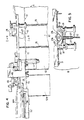
- FIG. 1 is a side elevational view of the inventive bag filling system
- FIG. 2 is a cross-sectional view taken along lines II-II of FIG. 1;
- FIG. 3 is a plan elevational view of the inventive bag filling system of FIG. 1, showing movement of the pincer means;
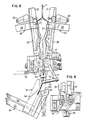
- FIG. 4 is a side elevational view of the inventive bag filling system as a filled, closed, and separated bag is withdrawn from the filling station;
- FIG. 5 is a cross-sectional view taken along lines V-V of FIG. 4;
- FIG. 6 is a plan cross-sectional view of the inventive bag filling system showing opening of the filling station jaws and a filled, closed, and severed bag being drawn from the filling station;
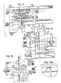
- FIG. 7 is a transverse cross-sectional view of the inventive bag filling system looking downstream from the filling station;
- FIG. 8 is a cross-sectional view taken along the lines VIII-VIII of FIG. 7;
- FIG. 9 is a partial plan elevational view of the portion of the inventive bag filling system downstream of the filling station when the grip jaws of the pincer means grip a filled bag;
- FIG. 10 is a partial plan elevational view of the portion of the inventive bag filling system downstream of the filling station on the grip jaws of the pincer means drawing a filled bag through the closing blocks and past the knife edge;
- FIG. 10A is a schematic side-elevational view of the knife edge cutting angle relative to the bags
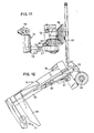
- FIG. 11 is a partial side-elevational view of the drive transmission means.
- FIG. 12 is a partial cross-sectional plan elevational view of the pincer means when the grip jaws therof are opened.
- the present invention is directed to a packaging system particularly adapted for loading reclosable zipper lock plastic bags initially arranged in a bag chain.
- Each bag is characterized by closed bottom and side edges and a reclosable upper end mouth having a pair of cooperatively interlocking fastener strip profiles formed with respective engageable rib and groove elements.
- FIG. 1 serves to generally illustrate the inventive bag filling system 10 in which zipper lock bags 12, arranged in a chain 11, pass laterally from right ot left as shown in FIG. 1 sequentially through a series of operations.
- Each bag is formed with a laterally directed zipper 13 (comprising the reclosable interlocking rib and groove profile strips) extending between the opposed side edges of the bag and defining a top fillable bag mouth.
- a laterally directed zipper 13 comprising the reclosable interlocking rib and groove profile strips
- Upstanding from the profile strips of the zipper 13 are front and rear pull flanges 14.
- the bags are partially separated from one another in the chain 11 by separation spaces 15, the separations 15 extending upwardly past the zipper 13 and to tops of the pull flanges 14.
- respective continuous strips 16 integrally connect the tops of the front and rear pull flanges 14 of all of the bags in the chain and thereby serve to connect the bags in continuous series.
- the connecting strips 16 have guide ribs 17 extending laterally continuously along their upper edge portions, serving as support rails so that the connected bags can be slidably drawn through the system 10. Removal of the strips 16 from the tops of the pull flanges results in the bags being separated from one another by virtue of the separations 15. In the preferred arrangement, the side edges of the pull flanges 14 for each bag are secured together at the separations 15, and the secured pull flange edges remaining secured after removal of the strips 16.
- the bags 12 are vertically draped and the chain 11 is disposed for advancement laterally from right to left as shown in FIG. 1 through the system 10.
- the system 10 is adapted to handle the bags 12 with their zippers closed, which is the typical disposition of the bags following manufacture.
- the system 10, as shown in FIG. 1, may be broken down into multiple regions of operation which sequentially act upon the bags in the chain 11.
- a stationary guide track element in the form of an upwardly sloped plow 20 having a laterally directed channel therethrough for preferably receiving only one of the guide ribs 17 therealong while the other guide rib and its connecting strip pass along the outside of the plow.
- the plow 20 serves to support and align the bag chain for entry into the bag filling and separating mechanism and straighten out any bags of the chain that may be flipped over such that all bags entering the mechanism are in a proper vertically draped disposition with their bag mouths facing upward.
- Region B defines a filling station in which each bag of the chain stops and is regularly aligned.
- the pull flanges 14 of the bag are adapted to be engaged and firmly opened apart in a direction transverse to the lateral movement of advancement of the bags through the system 10 for effecting opening of the zipper 13 of the bag, such that the bag may be filled.
- the pull flanges of the bag are drawn back together in the filling station, the bags being supported in the filling station on the guide track means respectively engaging with the guide ribs 17 of the bag.
- region C there operates a pincer means which moves between a first point located in region C and a second point substantially away from the filling station and serves to grasp each filled bag and draw the bag through the operations of the region C, the result of which is the filled bag is reclosed and separated from the upstream end of the bag chain 11.
- the pincer means moves the separated and filled bag fully away from the filling station to the second point at which its grasp on the bag is released.
- This pincer movement which controls the movement of the bags through the system can be automated. Alternately, the system can be simplified and the bags grasped and pulled through by a person's fingers.
- the upper ends of the bags are received in the filling station from the guide track device 20 between a par of jaws or arms 21 and 22. These arms are each supported for pivotal movement about vertical pins supporting their downstream ends.
- the jaws 21 and 22 are movable between a relatively closed position as shown in FIGS. 3-5 and an open position (the opening movement of the jaws being shown under way in FIG. 6).
- Each jaw comprises a platform surface on which is suitably disposed a guide structure 23 having a lip end 24 overhanging the platform and defining therebetween a separation space to serve as a track groove for slidably receiving the upper end of the continuous strip 16 of the bags such that the respective guide ribs 17 are held within the track groove for vertical grasping support of the bags in the filling station.
- a bag pull flange gripper means 26 having a vertically downwardly extending paddle portion 27 for engaging the inner surface of a respective bag pull flange.
- the paddle 27 is connected to a bracket 28 which is disposed for free pivotal movement about a transversely extending bar 29 mounted on the platform.
- the bracket 28 is loosely supported for a lost-motion effect on the bar 29, and is formed with a downwardly extending flange 30 on the other side of the bracket form the paddle 27.
- the flange 30 has an inwardly directed tooth 31 formed at its lower end for selectively engaging in any one of a vertical row of laterally directed tooth grooves 32 formed on the back wall of the platform's guide structure 23.
- the guide structures 23 are adjustably fixed by suitable means in channels 25 along the platforms of jaws 21 and 22 so that their relative position can be optimized for any specific size bag to be opened and filled.
- the paddles 27 of the filling station jaws are disposed between the continuous strips 16 of each bag as it enters the filling station, at which time the jaws 21 and 22 are in their relatively closed disposition as shown, for example, in FIGS. 3 and 5.
- the paddles 27 are kept slightly apart, thus avoiding contact friction between them, by virtue of spacer ribs 27A respectively disposed on the brackets 28 and extending inwardly thereof to abut one another. These ribs maintain spacing between the paddles and, when abutting one another, maintain the associated teeth and grooves 31 and 32 spaced clear of one another.
- the loose disposition of the brackets 28 and the spaced clear disposition of the teeth and grooves 31 and 32 enable the paddles 27 to drop freely downward between the pull flanges of the bag, abutting on top of the closed zipper 13.
- the bag surfaces tug the paddles slightly in the transversely inward direction, whereby the bracket teeth 31 engages in appropriate tooth grooves 32 locking the paddles 27 against possible rotational movement up and out from between the pull flanges.
- the paddles 27 serve to clamp the pull flanges of the bag such that the jaws 21 and 22, in opening, can pull the flanges 14 apart and thereby separate the closable zipper of each bag at the filling station.
- the vertical array of tooth grooves 32 for selective operation with the bracket tooth 31 serves as a self-adjusting locking device on the disposition of the paddles 27 which allows for possible manufacturing variations in the depth from the top of the bags at which the zipper 13 is situated.
- the paddles 27 need to rest on or near the zipper profiles. During the transfer of the bag chain, however, the paddles are pushed by weld spots closing together the ends of the zipper profiles of each bag. Thus, the paddles 27 need to be freely pivotable (about bars 29) to allow for movement of the weld spots thereunder, as well as to freely adjust for differences among bags in vertical height between zipper profiles and the tops of the pull flanges. Nevertheless, it is also necessary to prevent the paddles 27 from being free to pivot laterally out of the bag mouth during the bag opening phase. Thus, the selective locking action of the teeth 31 and grooves 32 cause the paddles 27 to be held against rotational movement for opening of the bag mouth and zipper profiles to permit filling. The loose, lost-motion disposition of the paddle brackets 28 on bars 29 enable the paddles to shift between the phases when the paddles 27 must be freely pivotable and when the paddles must be locked to grip the bag surfaces during spreading apart of the jaws 21 and 22.
- a closing station means 30A and a separating station means 40 serves to force back together the zipper profiles of the filled bag into closed interlock by utilizing a pair of transversely facing surfaces 31A and 32A between which the zipper portion 13 of the filled bag is passed.
- One of the facing surfaces 32A may be resiliently biased by a spring connection 33 about a pivot pin 34, as shown in FIG. 10, to effect a transverse pressure on the zipper passing between the closing station surfaces 31A and 32A, supporting the filled bag as well as effecting closing together of the zipper profiles.
- the zipper profiles are engaged in transversely opposed laterally running grooves 35 formed on the facing surfaces 31A and 32A. Each groove 35 is capable of fitting the respective zipper profile.
- a knife edge 41 Disposed above and just downstream of the closing station means 30A is a knife edge 41 which serves as the separation station means 40.
- the knife edge 41 extends transversely across the advancement path of the filled bag as shown in FIG. 10, and is mounted with a slight vertically upward rake as shown schematically in FIG. 10A to instill a downward force on the bag as it is cut.
- the knife edge engages each bag at the tops of the pull flanges 14 and just below the tops of the separations 15 for removing the continuous strips 16 from the bag.
- the filled bag is advanced past the knife edge 41 and in doing so passes into region D as an individual bag separated from the chain 11 as shown by bag 12A in FIG. 1.
- the removed continuous strips are advanced out of region C into region D, as shown by separated strips 16A in FIGS. 1 and 4, due to the further advancement of the remainder of the chain 11.
- the strips 16 are supported in region C for lateral movement above the filled bag being separated therefrom by virture of guide track elements 42 having lip flanges 43 defining a gap thereacross from platform surfaces 44 into which the continuous strips 16 extend such that the guide ribs 17 slidalby abut along the back surfaces of the lip flanges 43.
- a free-pivoting stop device 45 shown in FIG. 4 overlies the platform surfaces 44 over which the strips pass downstream of the separating station means 40.
- the stop device 45 has a vertically downward directed tooth portion 46 for engaging strips 16A against the platform surfaces 44 and a counterweight block portion 47.
- the stop device pivots about a pin mounting 48.
- the tooth portion 46 is prevented from pivoting counterclockwise as shown in FIG. 4 past vertical since the tooth portion 46 is too long to clear the platform surface 44 in such a counterclockwise movement, and thus the tooth holds the strips 16A against the platform surface to prevent backward movement thereof.
- pincer 50 advances the bags in the chain 11 and operates in regions C and D.
- the pincer 50 carries expandable jaw means 51 for grasping each filled bag in region C, as shown in FIG. 9, pulling the filling bag through the operations of region C, as shown in FIG. 10, and transporting the separated, individual bag fully away from regions B and C to where the jaw means open, as shown in FIG. 12, to release the bag.
- the pincer 50 is formed by an arm frame 52, at the free end of which the jaw means 51 is disposed and the other end of which is mounted for lateral rotation about a vertical pin 53, as shown in FIG. 12.
- the jaw means 51 is arranged with a first grasping jaw 54 stationarily mounted on the arm frame 52 and a second cooperating grasping jaw 55 in the form of a toggle plate pinned at one end on the arm frame 52 and at the other end on the outer end of a link arm 56 loosely supported on the arm frame 52.
- the opposed inner end of the link arm 56 projects through an opening 57 in the arm frame and is formed at the tip with a cam follower surface 58 which cooperates with a mounting wall edge 59 serving as a cam.
- the link arm 56 is biased inwardly on the arm frame 52 by a spring connection 60.
- a stop member 61 is formed on the link arm 56.
- the toggle-actuated jaw 55 closes onto the stationary jaw member 54 when the link arm 56 is relatively depressed through the opening 57 in the arm frame 52, with the recessed portion of the cam follower surface 58 on the link arm riding along the cam wall surface 59 and the stop 61 contained within the hollow of the opening 57.
- the cam follower surface 58 of the link arm is engaged against the cam wall surface 59 under the action of the spring 60.
- the toggle-actuated jaw 55 releases and spreads apart from the stationary jaw 54 when the relatively raised portion of the cam follower surface 58 on the link arm becomes engaged on the cam wall surface 59.
- the toggle-actuated jaw 55 is held in a spread-apart or open position relative to the other jaw 54 with continued movement of the relatively raised portion of the cam follower surface 58 over the cam wall 59 by virtue of the stop 61 being raised out of the opening 57 against the action of the spring 60 and lodging on the ledge surface of the arm frame 52 at the outer end of the opening 57.
- the toggle-actuated jaw 55 remains in the open configuration as shown in FIG. 12, by virtue of the engagement of the stop 61 on the ledge surface of the arm frame 52, until, referring to FIG. 3, the pincer 50 rotates back towards region C and the link arm 56 engages upon a projection 62 forcing the stop laterally back off the ledge of the arm frame 52 and, under the biasing action of the spring 60, into the opening 57.
- the jaw 55 closes onto the stationary jaw 54 when the abutment 62 has engaged in the link arm 56.
- the grip jaw means 51 is disposed in region C, as shown in FIG. 9, the grip jaws 54 and 55 grasping the pull flanges 14 of the filled bag therebetween, illustrated in FIG. 7.
- the jaws 54 and 55 tightened on the pull flanges of the filled bag advance the filled bag therebetween, illustrated in FIG. 7.
- the jaws 54 and 55 tightened on the pull flanges of the filled bag advance the filled bag laterally through region C stations and, as long as the filled bag pull flanges continue to be connected with the continuous strips 16 as shown in FIG.
- the opening and closing of the jaws 21 and 22 in the filling station of region B is effected by the rotation of a pair of interengaging gear wheels 70 and 71 respectively connected to the jaws 21 and 22 and rotatable about the vertical pin supports on which the jaws pivot.
- one gear wheel 71 is biased by spring connection 72 for rotational movement drawing the filling station jaws 21 and 22 into their aligned, closed position illustrated in FIG. 3.
- the other gear wheel 70 is connected with a drive transmission linkage 73 which serves to rotate gear wheel 70 and gear wheel 71, against the force of the spring 72 to cause the filling station jaws 21 and 22 to spread apart, as shown in FIG. 6, leading to opening and filling of the bag in the filling station.
- the drive transmission link means 73 is a lost-motion linkage wherein an elongated rod 74 has a free end 75 disposed for slidable movement through a support bracket 76 fixedly mounted on the pincer arm frame 52 adjacent a lower end thereof.
- the other end of the rod 74 is pin-connected to a link 77 which is fixed, such as by welding, to the gear wheel 70.
- An adjustable stop mechanism 78 in the form of a threaded double nut arrangement, is disposed along the outer length of the free end portion of the rod 74.
- the stop mechanism 78 serves to engage with rod support surfaces of the bracket 76 as the pincer 50 moves in region D carrying a separated and filled bag to its second point of disposition for releasing the filled bag.
- the degree to which the filling station jaws 21 and 22 spread apart may be varied, such as depending upon the size of the bag being filled, by linear adjustment of the stop mechanism 78 along the length of the rod 74.
- the lateral arc movement of the arm frame of the pincer 50 in drawing a filled bag from region C fully into region D is powered by a foot treadle 80, operatively connected through a drive transmission means 81 to the arm frame 52, as indicated in FIG. 1.
- the drive transmission means 81 as illustrated in FIGS. 3 and 11, is such that depression of the foot treadle 80 tensions a wire 82 connected at its other end to a wheel 83 which operates a coaxial bevel gear 84, bringing about rotation of the wheel 83 and bevel gear 84.
- a pivotal lever arm may be used in place of the wheel 83.
- the bevel gear 84 engages with a bevel gear 85 fixedly connected to the arm frame 52 and rotatable about the vertical axis of the pin 53 about which the arm frame rotates.
- depression of the foot treadle 80 brings about rotation of the arm frame bevel gear 85 such that the pincer passes from right to left as shown in FIG. 3 through its arc of movement from its first point of disposition in region C to its second point of disposition in region D.
- the wheel 83 is biased by spring connection 86 for rotational movement contrary to depression of the foot treadle 80.
- the bias of the spring connection 86 on the wheel 83 is effectively unopposed and the wheel 83 rotates driving arm fram bevel gear 85 in a counter-clockwise direction, as illustrated in FIG. 3, in turn driving the pincer 50 in its lateral arc movement from the second disposition point in region D back to the first disposition point in region C.
- the bags 12 of the chain 11 are sequentially indexed through the system 10 one bag at a time each time the foot treadle 80 is depressed.
- said apparatus comprises a bag filling station having supporting and separating jaw means for slidably engaging said ribs and separating said pull flanges and thereby said zipper of each bag for filling, and, downstream of said filling station, means for closing the zipper of said filled bag and means for separating said connecting strips from the tops of said pull flanges of said filled bag and thereby separating said filled bag
- said other end of said arm is mounted on a pivot such that said arm moves in an arc.
- a lost-motion linkage means connected between said arm and said filling station jaw means causes said jaw means to effect separating of said pull flanges upon movement of said arm away from said first point.
- said lost-motion linkage means is adjustable to vary the distance of separation of said pull flanges.
- the invention also provides for the following:
- each bag having a reclosable upper end mouth having interlocking fastener strip profiles running laterally across opposed inner facing surfaces of said mouth of said bag, apparatus for opening each bag mouth and separating said interlocking fastener strip profiles thereof comprising:
- a pair of ribs respectively associated with said paddles extend transversely toward each other for abutting and transversely spacing said paddles when said arms are in the closed position.
- an apparatus for aligning said bags of said chain as said chain comprising:
Landscapes
- Engineering & Computer Science (AREA)
- Mechanical Engineering (AREA)
- Making Paper Articles (AREA)
- Supplying Of Containers To The Packaging Station (AREA)
- Containers And Plastic Fillers For Packaging (AREA)
- Basic Packing Technique (AREA)
- Closing Of Containers (AREA)
Claims (18)
- Verfahren zum aufeinanderfolgenden Füllen von in Form einer Kette zugeführten Beuteln, wobei die Beutel einen geschlossenen Boden und geschlossene Seitenkanten haben und fluchtende obere Enden besitzen, die durch verrastbare, wiederverschliepbare, mit Profilen versehene Verschlußeinrichtungen verschlossen sind, von denen ein Paar von Aufreißlaschen nach oben absteht, wobei die Beutel in der Kette miteinander durch kontinuierliche Verbindungsstreifen verbunden sind, die oberhalb der Aufreifllaschen angeordnet sind, und wobei die zu einer Kette verbundenen Beutel an ihren benachbarten Seitenkanten durch Einschnitte voneinander getrennt sind, die sich nach oben über die Verschlußeinrichtungen hinaus zu den oberen Enden der Aufreißlaschen erstrecken, wobei das genannte Verfahren umfaßt:
man läßt die Kette bei vertikal auf Halterungseinrichtungen aufgehängten Beutein einen in Längsrichtung verlaufenden Pfad passieren, längs welchem jeder der Beutel an seinen Verschlußeinrichtungen zum Füllen geöffnet wird, wobei die Verschlußeinrichtungen jedes der gefüllten Beutel anschließend verrastend geschlossen werden und wobei von jedem der geschlossenen Beutel die betreffenden Streifen von ihren betreffenden Aufreißlaschen abgetrennt werden, um den gefüllten und geschlossenen Beutel von der Kette zu trennen,
man erfaßt jeden der gefüllten Beutel der Kette vor dem Schließen der Verschlußeinrichtungen an dem gefüllten Beutel und zieht den gefüllten Beutel durch den in Längsrichtung verlaufenden Pfad und über diesen hinaus, um das Passieren zu bewirken und den gefüllten, geschlossenen und abgetrennten Beutel von der Kette wegzutragen, und
man gewinnt die Energie für das Öffnen jeder der Beutelverschlußeinrichtungen allein durch das Ziehen an dem gefüllten, geschlossenen und abgetrennten Beutel, der von der Kette weggetragen wird. - Verfahren nach Anspruch 1, bei dem das Ziehen von Hand bewirkt wird.
- Verfahren nach Anspruch 1, welches (Verfahren) umfaßt:
die Kette wird weiterbewegt, während der vorderste Beutel derselben eine Schneidstation passiert, welche eine Messerkante aufweist, um die Verbindungsstreifen von den Aufreißlaschen zu trennen, so daß der vorderste Beutel von der Kette zwischen den getrennten Seiten dieses vordersten Beutels abgetrennt wird, und
man beendet das Weiterbewegen der Kette, wenn der vorderste Beutel von dieser Kette getrennt ist. - Vorrichtung zum aufeinanderfolgenden Füllen von in Form einer Kette zugeführten BeuteIn, wobei die Beutel einen geschlossenen Boden und geschlossene Seitenkanten haben und fluchtende obere Enden besitzen, die durch verrastbare, wiederverschließbare, mit Profilen versehene Verschlußeinrichtungen (13) verschlossen sind, von denen ein Paar von Aufreißlaschen (14) nach oben absteht, wobei die Beutel in der Kette miteinander durch kontinuierliche Verbindungsstreifen (16) verbunden sind, die oberhalb der Aufreißlaschen angeordnet sind und wobei die zu einer Kette verbundenen Beutel an ihren benachbarten Seitenkanten durch Einschnitte (15) voneinander getrennt sind, die sich nach oben über die Verschlußeinrichtungen hinaus zu den oberen Enden der Aufreißlaschen erstrecken, wobei die genannte Vorrichtung umfaßt:
eine Füllstationseinrichtung (B) zum Auseinanderspreizen der Aufreißlaschen und der Verschlußeinrichtungen jedes der Beutel zum Öffnen dieses Beutels zum Füllen,
eine Verschlußstationseinrichtung (C) zum Verrasten der Verschlußeinrichtungen,
eine Trennstationseinrichtung zum Entfernen der kontinuierlichen Streifen von jedem der Beutel zwischen den Einschnitten, und
Weiterbewegungseinrichtungen (50) zum Erfassen jedes der geöffneten Beutel und zum betriebsmäßigen Hindurchziehen des geöffneten Beutels durch die Verschluß- und die Trennstationseinrichtung, derart, daß die Kette schrittweise Beutel für Beutel durch die Vorrichtung hindurch zu einem gemeinsamen Punkt bewegt wird, wo ein gefüllter Beutel von der Kette abgetrennt wird. - Vorrichtung nach Anspruch 4, bei der die Verschlußstationseinrichtung eine Paar von Oberflächen (3lA, 32A) umfaßt, zwischen denen die Verschlußeinrichtungen hindurchgeführt werden, wobei die Oberflächen eine vertikale Reihe von Nuten (35) haben, die sich koaxial zu den Verschlußeinrichtungen erstrecken, und wobei jede Nut individuell geeignet ist, das betreffende Verschlußprofil passend aufzunehmen, um Variationen in der relativen vertikalen Anordnung der Verschlußeinrichtungen an den Beuteln aufzufangen.
- Vorrichtung nach Anspruch 4, bei der die Trennstationseinrichtung eine Messerkante (41) unfaßt, die sich quer über den Pfad erstreckt, längs welchem die Beutel von der Füllstationseinrichtung vorrücken, wobei die Messerkante die Beutel auf einer Höhe durchschneidet, die unterhalb der oberen Enden der Aufreißlaschen liegt.
- Vorrichtung nach Anspruch 4, bei der die Füllstationseinrichtung Klaueneinrichtungen (21, 22) umfaßt, die aufspreizbar sind, um ein Auseinanderspreizen der Aufreißlaschen und der Verschlußeinrichtungen zu bewirken.
- Vorrichtung nach Anspruch 7, dadurch gekennzeichnet, daß die Klaueneinrichtungen Streifenhalteeinrichtungen aufweisen, um den Beutel daran durch Eingriff mit den Streifen zu haltern, wobei die Streifenhalteeinrichtungen einstellbar längs der Klaueneinrichtungen angeordnet sind.
- Vorrichtung nach Anspruch 4, bei der die Füllstationseinrichtung Paddel (27) umfaßt, um senkrecht zwischen die Streifen und Aufreißlaschen der Beutel vorzustehen und sich in der Nähe der Verschlußeinrichtungen abzustützen, wobei die Paddel für eine Schwenkbewegung in Längsrichtung montiert sind.
- Vorrichtung nach Anspruch 9, bei der den Paddeln Verriegelungseinrichtungen (31, 32) zugeordnet sind, welche einrasten, um die Schwenkbewegung der Paddel zu verhindern, wenn der Beutel geöffnet wird.
- Vorrichtung nach Anspruch 10, bei der die Verriegelungseinrichtungen auf verschiedenen Schwenkpositionen der Paddel angeordnet sind, die sich aufgrund relativer Unterschiede in der vertikalen Tiefe zwischen den oberen Enden der Streifen und den Verschlußeinrichtungen der Beutel ergeben.
- Vorrichtung nach Anspruch 4, bei der die Einrichtungen zum Weiterbewegen jeden der geöffneten Beutel unterhalb der oberen Enden der Aufreißlaschen des betreffenden Beutels erfassen.
- Vorrichtung nach Anspruch 4, bei der die Einrichtungen zum Weiterbewegen eine Antriebsübertragungseinrichtung (81) umfassen, die mit der Füllstationseinrichtung derart verbunden ist, daß die Zugwirkung der Einrichtungen zum Weiterbewegen den Aufspreizvorgang der Füllstationseinrichtung aktiviert.
- Vorrichtung nach Anspruch 13, bei der die Einrichtungen zum Weiterbewegen von Hand betätigt werden.
- Vorrichtung nach Anspruch 4, bei der die Einrichtungen zum Weiterbewegen eine Klemmvorrichtung (50) umfassen, welche an einem Ende auseinanderspreizbare Greifklauen zum Erfassen und Freigeben der Beutel aufweist und am anderen Ende eine Schwenkverbindung, derart, daß sich die Klemmvorrichtung längs eines Bogens bewegt.
- Vorrichtung nach Anspruch 15, bei der mindestens eine der Greifklauen (55) über eine Kurvenbahn betätigt wird, um von der anderen Greifklaue abgespreizt zu werden, nachdem die Klemmvorrichtung jeweils einen der Beutel voll durch die Verschluß- und die Trennstationseinrichtung hindurch bewegt hat, und um von der anderen Greifklaue abgespreizt zu bleiben, während sich die Klemmvorrichtung zurück in Richtung auf den nachfolgenden geöffneten Beutel der Kette bewegt, bis sie erneut durch die Kurvenbahn betätigt wird, um bezüglich der anderen Greifklaue zu schließen, wenn sich der anschließend geöffnete Beutel zwischen den Greifklauen befindet.
- Vorrichtung nach Anspruch 15, bei der die Klemmvorrichtung durch die Betätigung eines Pedals und über Verbindungseinrichtungen, über die dieses Pedal mit der Klemmvorrichtung in Wirkverbindung steht, auf dem Bogen um die Schwenkverbindung bewegt wird.
- Vorrichtung nach Anspruch 4, welche ferner Einrichtungen umfaßt, um eine Rückwärtsbewegung der Streifen in Richtung auf die Füllstationseinrichtung zu verhindern, nachdem die Streifen von den Beuteln entfernt worden sind.
Applications Claiming Priority (2)
| Application Number | Priority Date | Filing Date | Title |
|---|---|---|---|
| US87444786A | 1986-06-16 | 1986-06-16 | |
| US874447 | 1986-06-16 |
Publications (3)
| Publication Number | Publication Date |
|---|---|
| EP0249868A2 EP0249868A2 (de) | 1987-12-23 |
| EP0249868A3 EP0249868A3 (en) | 1988-12-07 |
| EP0249868B1 true EP0249868B1 (de) | 1991-03-20 |
Family
ID=25363795
Family Applications (1)
| Application Number | Title | Priority Date | Filing Date |
|---|---|---|---|
| EP87108373A Expired - Lifetime EP0249868B1 (de) | 1986-06-16 | 1987-06-10 | Füllmaschine und Füllverfahren für Säcke mit elastischen Komplementärverschlussstreifen |
Country Status (6)
| Country | Link |
|---|---|
| EP (1) | EP0249868B1 (de) |
| JP (1) | JPS638A (de) |
| AU (1) | AU599921B2 (de) |
| DE (1) | DE3768711D1 (de) |
| DK (1) | DK301187A (de) |
| ES (1) | ES2022207B3 (de) |
Families Citing this family (5)
| Publication number | Priority date | Publication date | Assignee | Title |
|---|---|---|---|---|
| DK265790D0 (da) * | 1990-11-06 | 1990-11-06 | Thorsted Maskiner As | Fremgangsmaade og apparat til fyldning af poseemner tilfoert i en kontinuerlig bane |
| WO1995004651A1 (en) * | 1993-08-05 | 1995-02-16 | Minigrip Flexible Packaging Limited | Plastic bag chain with support means |
| SE504739C2 (sv) * | 1994-03-01 | 1997-04-14 | Endre Joo | Förfarande och anordning för tillverkning, fyllning och förslutning av återförslutbara påsar |
| CN103004603A (zh) * | 2012-12-27 | 2013-04-03 | 福建农林大学 | 一种蝴蝶兰品种的植株再生方法 |
| DK179277B1 (da) * | 2017-03-27 | 2018-03-26 | Schur Tech As | Posebane samt fremgangsmåde og apparat til pakning af emner |
Family Cites Families (4)
| Publication number | Priority date | Publication date | Assignee | Title |
|---|---|---|---|---|
| GB994307A (en) * | 1961-11-27 | 1965-06-02 | Seisan Nipponsha Kk | Material for forming plastics bags and bags made therefrom |
| US3813845A (en) * | 1972-06-23 | 1974-06-04 | Gen Films Inc | Filling and sealing system |
| JPS5232460U (de) * | 1975-08-27 | 1977-03-07 | ||
| US4490959A (en) * | 1982-09-30 | 1985-01-01 | Signode Corporation | Method and mechanism for filling bags |
-
1986
- 1986-09-08 AU AU62419/86A patent/AU599921B2/en not_active Ceased
- 1986-10-03 JP JP61234716A patent/JPS638A/ja active Pending
-
1987
- 1987-06-10 ES ES87108373T patent/ES2022207B3/es not_active Expired - Lifetime
- 1987-06-10 EP EP87108373A patent/EP0249868B1/de not_active Expired - Lifetime
- 1987-06-10 DE DE8787108373T patent/DE3768711D1/de not_active Expired - Fee Related
- 1987-06-12 DK DK301187A patent/DK301187A/da not_active Application Discontinuation
Also Published As
| Publication number | Publication date |
|---|---|
| EP0249868A3 (en) | 1988-12-07 |
| JPS638A (ja) | 1988-01-05 |
| DE3768711D1 (de) | 1991-04-25 |
| DK301187D0 (da) | 1987-06-12 |
| EP0249868A2 (de) | 1987-12-23 |
| AU599921B2 (en) | 1990-08-02 |
| ES2022207B3 (es) | 1991-12-01 |
| DK301187A (da) | 1987-12-17 |
| AU6241986A (en) | 1987-12-17 |
Similar Documents
| Publication | Publication Date | Title |
|---|---|---|
| US4848064A (en) | Zipper bag filling machine and method | |
| EP0453522B1 (de) | Maschine zum herstellen, füllen, verschliessen und getrennten verpacken wiederverschliessbarer behälter | |
| US7048441B2 (en) | Method and system for filling goods in bags from a coherent series of bag members | |
| US4665552A (en) | Zipper equipped bags and method of and means for manually filling and separating them | |
| US3599388A (en) | Method of and apparatus for forming and loading containers | |
| KR101770801B1 (ko) | 만두제조장치 | |
| US4850178A (en) | Device for opening a double link bag chain | |
| US4452597A (en) | Method and apparatus for forming stacks of sacks | |
| EP0825117A1 (de) | Verpackungsverfahren und - Maschine zum Füllen von Beuteln eines Bandes von zusammenhängenden Beuteln | |
| JPH0455928B2 (de) | ||
| MXPA97006162A (en) | Packing machine, material and met | |
| NO853726L (no) | Anordning og fremgangsmaate til pakking av et produkt i enkeltpakninger. | |
| JPH11503697A (ja) | 底部装填バスケット形カートンの装填装置 | |
| CA1128124A (en) | Battery plate wrapping machine | |
| DE2618690C3 (de) | Verpackungsmaschine | |
| JPH1035604A (ja) | 連続包装機械 | |
| EP0249868B1 (de) | Füllmaschine und Füllverfahren für Säcke mit elastischen Komplementärverschlussstreifen | |
| US4490959A (en) | Method and mechanism for filling bags | |
| US5056202A (en) | Apparatus for making and transporting stacks of foil sections | |
| US4730439A (en) | Method and apparatus for packaging a product in individual vacuum sealed packets | |
| CN212829547U (zh) | 多列包装袋自动化包装线 | |
| US4522017A (en) | Registration of bags in a filling machine | |
| EP0555321B1 (de) | Vorrichtung zum öffnen und schliessen seitlich verbundener bautelwände zum zwecke des befüllens | |
| JP3330646B2 (ja) | 袋を製造し、充填し、密封する方法 | |
| FR2601974A1 (fr) | Procede et dispositif pour la coupe transversale et le long des deux bords et pour la couture de produits plats en bande, notamment de tissu eponge. |
Legal Events
| Date | Code | Title | Description |
|---|---|---|---|
| PUAI | Public reference made under article 153(3) epc to a published international application that has entered the european phase |
Free format text: ORIGINAL CODE: 0009012 |
|
| AK | Designated contracting states |
Kind code of ref document: A2 Designated state(s): BE CH DE ES FR GB IT LI SE |
|
| PUAL | Search report despatched |
Free format text: ORIGINAL CODE: 0009013 |
|
| AK | Designated contracting states |
Kind code of ref document: A3 Designated state(s): BE CH DE ES FR GB IT LI SE |
|
| 17P | Request for examination filed |
Effective date: 19881128 |
|
| 17Q | First examination report despatched |
Effective date: 19900710 |
|
| GRAA | (expected) grant |
Free format text: ORIGINAL CODE: 0009210 |
|
| AK | Designated contracting states |
Kind code of ref document: B1 Designated state(s): BE CH DE ES FR GB IT LI SE |
|
| REF | Corresponds to: |
Ref document number: 3768711 Country of ref document: DE Date of ref document: 19910425 |
|
| ET | Fr: translation filed | ||
| ITF | It: translation for a ep patent filed | ||
| PLBE | No opposition filed within time limit |
Free format text: ORIGINAL CODE: 0009261 |
|
| STAA | Information on the status of an ep patent application or granted ep patent |
Free format text: STATUS: NO OPPOSITION FILED WITHIN TIME LIMIT |
|
| 26N | No opposition filed | ||
| PGFP | Annual fee paid to national office [announced via postgrant information from national office to epo] |
Ref country code: FR Payment date: 19930505 Year of fee payment: 7 |
|
| PGFP | Annual fee paid to national office [announced via postgrant information from national office to epo] |
Ref country code: SE Payment date: 19930506 Year of fee payment: 7 |
|
| PGFP | Annual fee paid to national office [announced via postgrant information from national office to epo] |
Ref country code: BE Payment date: 19930511 Year of fee payment: 7 |
|
| PGFP | Annual fee paid to national office [announced via postgrant information from national office to epo] |
Ref country code: CH Payment date: 19930517 Year of fee payment: 7 |
|
| PGFP | Annual fee paid to national office [announced via postgrant information from national office to epo] |
Ref country code: ES Payment date: 19930519 Year of fee payment: 7 |
|
| PGFP | Annual fee paid to national office [announced via postgrant information from national office to epo] |
Ref country code: GB Payment date: 19930528 Year of fee payment: 7 |
|
| PGFP | Annual fee paid to national office [announced via postgrant information from national office to epo] |
Ref country code: DE Payment date: 19930719 Year of fee payment: 7 |
|
| PG25 | Lapsed in a contracting state [announced via postgrant information from national office to epo] |
Ref country code: GB Effective date: 19940610 |
|
| PG25 | Lapsed in a contracting state [announced via postgrant information from national office to epo] |
Ref country code: SE Effective date: 19940611 Ref country code: ES Free format text: LAPSE BECAUSE OF EXPIRATION OF PROTECTION Effective date: 19940611 |
|
| PG25 | Lapsed in a contracting state [announced via postgrant information from national office to epo] |
Ref country code: LI Effective date: 19940630 Ref country code: CH Effective date: 19940630 Ref country code: BE Effective date: 19940630 |
|
| BERE | Be: lapsed |
Owner name: MINIGRIP EUROPE G.M.B.H. Effective date: 19940630 |
|
| EUG | Se: european patent has lapsed |
Ref document number: 87108373.9 Effective date: 19950110 |
|
| GBPC | Gb: european patent ceased through non-payment of renewal fee |
Effective date: 19940610 |
|
| PG25 | Lapsed in a contracting state [announced via postgrant information from national office to epo] |
Ref country code: FR Effective date: 19950228 |
|
| REG | Reference to a national code |
Ref country code: CH Ref legal event code: PL |
|
| PG25 | Lapsed in a contracting state [announced via postgrant information from national office to epo] |
Ref country code: DE Effective date: 19950301 |
|
| EUG | Se: european patent has lapsed |
Ref document number: 87108373.9 |
|
| REG | Reference to a national code |
Ref country code: FR Ref legal event code: ST |
|
| REG | Reference to a national code |
Ref country code: ES Ref legal event code: FD2A Effective date: 19990601 |
|
| PG25 | Lapsed in a contracting state [announced via postgrant information from national office to epo] |
Ref country code: IT Free format text: LAPSE BECAUSE OF NON-PAYMENT OF DUE FEES;WARNING: LAPSES OF ITALIAN PATENTS WITH EFFECTIVE DATE BEFORE 2007 MAY HAVE OCCURRED AT ANY TIME BEFORE 2007. THE CORRECT EFFECTIVE DATE MAY BE DIFFERENT FROM THE ONE RECORDED. Effective date: 20050610 |