EP0453522B1 - Maschine zum herstellen, füllen, verschliessen und getrennten verpacken wiederverschliessbarer behälter - Google Patents
Maschine zum herstellen, füllen, verschliessen und getrennten verpacken wiederverschliessbarer behälter Download PDFInfo
- Publication number
- EP0453522B1 EP0453522B1 EP90912509A EP90912509A EP0453522B1 EP 0453522 B1 EP0453522 B1 EP 0453522B1 EP 90912509 A EP90912509 A EP 90912509A EP 90912509 A EP90912509 A EP 90912509A EP 0453522 B1 EP0453522 B1 EP 0453522B1
- Authority
- EP
- European Patent Office
- Prior art keywords
- web
- machine
- belt
- containers
- belts
- Prior art date
- Legal status (The legal status is an assumption and is not a legal conclusion. Google has not performed a legal analysis and makes no representation as to the accuracy of the status listed.)
- Expired - Lifetime
Links
- 238000004806 packaging method and process Methods 0.000 title claims abstract description 19
- 238000007789 sealing Methods 0.000 claims abstract description 19
- 229920001169 thermoplastic Polymers 0.000 claims abstract description 4
- 239000004416 thermosoftening plastic Substances 0.000 claims abstract description 4
- 238000005520 cutting process Methods 0.000 claims description 9
- 239000000463 material Substances 0.000 claims description 7
- 241000842962 Apoda limacodes Species 0.000 claims description 5
- 239000005022 packaging material Substances 0.000 claims description 4
- 230000000452 restraining effect Effects 0.000 claims description 4
- 230000008093 supporting effect Effects 0.000 claims description 3
- 238000011144 upstream manufacturing Methods 0.000 claims 2
- 230000000737 periodic effect Effects 0.000 abstract 1
- 238000010276 construction Methods 0.000 description 5
- 238000005429 filling process Methods 0.000 description 3
- 235000013305 food Nutrition 0.000 description 3
- 230000013011 mating Effects 0.000 description 3
- 239000004033 plastic Substances 0.000 description 3
- 238000004519 manufacturing process Methods 0.000 description 2
- 239000012815 thermoplastic material Substances 0.000 description 2
- 230000033228 biological regulation Effects 0.000 description 1
- 230000007812 deficiency Effects 0.000 description 1
- 229940079593 drug Drugs 0.000 description 1
- 239000003814 drug Substances 0.000 description 1
- 238000009459 flexible packaging Methods 0.000 description 1
- 230000012447 hatching Effects 0.000 description 1
- 230000014759 maintenance of location Effects 0.000 description 1
- 238000002483 medication Methods 0.000 description 1
- 238000000034 method Methods 0.000 description 1
- 238000003825 pressing Methods 0.000 description 1
- 238000003908 quality control method Methods 0.000 description 1
- 238000000926 separation method Methods 0.000 description 1
Images

Classifications
-
- B—PERFORMING OPERATIONS; TRANSPORTING
- B65—CONVEYING; PACKING; STORING; HANDLING THIN OR FILAMENTARY MATERIAL
- B65B—MACHINES, APPARATUS OR DEVICES FOR, OR METHODS OF, PACKAGING ARTICLES OR MATERIALS; UNPACKING
- B65B9/00—Enclosing successive articles, or quantities of material, e.g. liquids or semiliquids, in flat, folded, or tubular webs of flexible sheet material; Subdividing filled flexible tubes to form packages
- B65B9/06—Enclosing successive articles, or quantities of material, in a longitudinally-folded web, or in a web folded into a tube about the articles or quantities of material placed upon it
- B65B9/08—Enclosing successive articles, or quantities of material, in a longitudinally-folded web, or in a web folded into a tube about the articles or quantities of material placed upon it in a web folded and sealed transversely to form pockets which are subsequently filled and then closed by sealing
- B65B9/093—Enclosing successive articles, or quantities of material, in a longitudinally-folded web, or in a web folded into a tube about the articles or quantities of material placed upon it in a web folded and sealed transversely to form pockets which are subsequently filled and then closed by sealing the web having intermittent motion
-
- B—PERFORMING OPERATIONS; TRANSPORTING
- B65—CONVEYING; PACKING; STORING; HANDLING THIN OR FILAMENTARY MATERIAL
- B65B—MACHINES, APPARATUS OR DEVICES FOR, OR METHODS OF, PACKAGING ARTICLES OR MATERIALS; UNPACKING
- B65B43/00—Forming, feeding, opening or setting-up containers or receptacles in association with packaging
- B65B43/26—Opening or distending bags; Opening, erecting, or setting-up boxes, cartons, or carton blanks
- B65B43/267—Opening of bags interconnected in a web
-
- B—PERFORMING OPERATIONS; TRANSPORTING
- B65—CONVEYING; PACKING; STORING; HANDLING THIN OR FILAMENTARY MATERIAL
- B65B—MACHINES, APPARATUS OR DEVICES FOR, OR METHODS OF, PACKAGING ARTICLES OR MATERIALS; UNPACKING
- B65B61/00—Auxiliary devices, not otherwise provided for, for operating on sheets, blanks, webs, binding material, containers or packages
- B65B61/04—Auxiliary devices, not otherwise provided for, for operating on sheets, blanks, webs, binding material, containers or packages for severing webs, or for separating joined packages
- B65B61/06—Auxiliary devices, not otherwise provided for, for operating on sheets, blanks, webs, binding material, containers or packages for severing webs, or for separating joined packages by cutting
-
- B—PERFORMING OPERATIONS; TRANSPORTING
- B65—CONVEYING; PACKING; STORING; HANDLING THIN OR FILAMENTARY MATERIAL
- B65B—MACHINES, APPARATUS OR DEVICES FOR, OR METHODS OF, PACKAGING ARTICLES OR MATERIALS; UNPACKING
- B65B61/00—Auxiliary devices, not otherwise provided for, for operating on sheets, blanks, webs, binding material, containers or packages
- B65B61/18—Auxiliary devices, not otherwise provided for, for operating on sheets, blanks, webs, binding material, containers or packages for making package-opening or unpacking elements
- B65B61/188—Auxiliary devices, not otherwise provided for, for operating on sheets, blanks, webs, binding material, containers or packages for making package-opening or unpacking elements by applying or incorporating profile-strips, e.g. for reclosable bags
Definitions
- the present invention relates to a form, fill, seal and separate packaging machine of the type primarily intended for use in packaging material in reclosable containers.
- the packaging machine of this invention is uniquely characterized by its means for transporting the web through the machine such that material may be placed into the partially filled reclosable containers along a constant, horizontal path of travel.
- the reclosable container is formed by wrapping the plastic web around a generally vertical fill tube, mating the opposed parts of the zipper-type lock to form a tube, and then filling the receptacles from an open end.
- US-A-4 514 962 discloses an apparatus with a filling station for seriatim filling of closed bottom bags of the kind supplied in a chain and wherein the bags have closed sides and aligned tops closed by reclosable profiled fastener means from which a pair of confronting lip flanges project upwardly and extend continuously along the top of the chain, and comprising: separable clamping means for receiving each of said lip flanges therebetween and having an open phase permitting relative movement of the lip flanges and the clamping means, and a clamping phase wherein said lip flanges are firmly clamped by said clamping means; means for cyclically operating said clamping means through each of said phases, and adapted in said clamping phase for actuating the clamping means for pulling said lip flanges apart and thereby separating said reclosable fastener means of each bag at said filling station: and means for advancing
- the present invention relates to a form, fill, seal and separate packaging machine of the type primarily intended for use in packaging material in reclosable containers. More specifically, the packaging machine of this invention utilizes a base web of thermoplastic material having mating portions of a zipper-type reclosable seal disposed longitudinally along the center of the web. The plastic web is folded onto itself so that the mating parts of the seal lock, and this folded web enters the work stations of the packaging machine for forming, filling, sealing and separating the final reclosable containers.
- a control drive means is provided to regulate the intermittent travel of the web through the packaging machine so that the various forming, filling, sealing and separating steps are performed simultaneously as the flow of web through the machine is periodically stopped.
- the folded web is initially received by first web belt means which direct the folded web into a first station for spot sealing the zipper-type lock at intervals corresponding to the final container width.
- Means for forming a side seal normal to the closure strips are provided downstream of the means for spot sealing.
- means for partially severing the side seals to define partially formed containers which are open at their free edges held between the first web belt means.
- the partially formed containers then advance to the means for filling wherein a pair of opposed bag opening means grip the free edges of the folded web and pull them outwardly to define an open mouth for filling the container.
- a pair of opposed bag opening means grip the free edges of the folded web and pull them outwardly to define an open mouth for filling the container.
- a load support conveyor is provided immediately beneath the means for filling and extending therefrom beyond the means for cutting and thereby separating the completed containers.
- the load support conveyor means is in abutting, supporting relation to the fold of the web, thereby reducing, if not virtually eliminating, mechanical stresses placed on the reclosable seal as each container is filled.
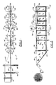
- FIG. 1 and 2 illustrate the packaging machine of this invention, generally indicated as 10.
- Packaging machine 10 utilizes a folded web 12 of thermoplastic material for forming the containers.
- web supply means comprising a reel 14 and delivery rollers 16 and 18 as well as turning rollers 20 provide a supply of web 12 to the remainder of packaging machine 10.
- web 12 is folded, and reference numeral 22 designates the fold.
- Thermoplastic web 12 is provided with a pair of mated, resealable closure strips substantially adjacent the fold, and these closure strips define the zipper-type lock 24 by which the completed container is reclosable.
- first web belt means comprising a pair of first endless belts 26 and 28. Endless belts 26 and 28 are driven in the direction shown by arrows A by control drive means comprising machine drive rollers 30 and 32. A plurality of guide rollers 34 are also provided for belts 26 and 28. Finally, a pair of festoon rollers 36 and 38 also define elements of the first web belt means, and the festoon rollers 36 and 38 are movable back and forth in the direction normal to the path of travel of web 12 through machine 10 whereby the partially filled container may be opened for filling, as explained hereinafter.
- folded web 12 is turned by rollers 20 such that free edges 40 are received and held between belts 26 and 28.
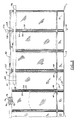
- Positive retention of free edges 40 between belts 26 and 28 is assured by the provision of first web holding means 42 fixedly mounted adjacent belt 26 opposite free edges 40 and a plurality of biased second web holding means 44 mounted in biased engagement adjacent belt 28. Because second web holding means 44 are biased toward belt 28, free edges 40 of folded web 12 are held firmly between belts 26 and 28 and travel therewith as indicated by arrows A. Further details of this structure may be seen in the views of Figs. 4 and 5.
- spot sealer 46 is actuated to seal zipper-type lock 24 as indicated at 48 in the view of Fig. 3.
- the distance between spot seals 48 defines the width of the finished container.
- side seal heater bar 50 further includes severing means 52 for substantially bisecting the side seals 54 formed by side seal heater bars 50.
- severing means 52 for substantially bisecting the side seals 54 formed by side seal heater bars 50.
- filling means 58 comprises a first web clamp 60 mounted in engaging, restraining relation to first belts 26 and 28 and free ends 40 held therebetween downstream of the side seal heater bars 50.
- First web clamp 60 is shown in its open position in the view of Fig. 4, and is closed in the view of Fig. 5. It should be noted that as clamp 60 closes, drive rollers 30 and 32 are stopped. It should also be noted that the drive rollers 30 and 32 are periodically stopped for operation of the various work stations of machine 10.
- the filling means 58 further comprises a second web clamp 62 also mounted in engaging, restraining relation to first belts 26 and 28 downstream of first web clamps 60.
- the second clamp 62 is also shown in its open position.
- drive rollers 30 and 32 would actually reverse direction so that first belts 26 and 28 and their corresponding free edges 40 of folded web 12 could be opened as shown in the view of Fig. 5.
- Second web clamp 62 is closed as shown in the view of Fig. 5 when mouth 64 of the partially severed container is fully opened as shown in that drawing. Simultaneous with the closing of second web clamp 62, drive rollers 30 and 32 would again be stopped from their reverse direction.
- first bag opening means and second bag opening means are similarly constructed, their structural elements have been assigned like reference numerals.
- first bag opening means 66 and second bag opening means 68 are similarly constructed, their structural elements have been assigned like reference numerals.
- each of the bag opening means 66 and 68 comprise a cylinder having an extendable/retractable rod 72 extending therefrom. The movement of rod 72 is indicated by directional arrows B.
- cylinders 70 are pivotally mounted to a frame element (not shown) of machine 10.
- each rod 72 Distal ends of each rod 72 are pivotally mounted to corresponding blocks 74 having a belt and web slot 76 formed therein whereby belts 26 and 28 and their corresponding free edges 40 of folded web 12 may pass therethrough.
- Mounted within each of the blocks 74 is a pair of movable fingers 78.
- movable fingers 78 are retracted so as not to interfere with the movement of belts 26 and 28 as well as free edges 40 through belt and web slot 76.
- fingers 78 are extended to grip belt 26 and its free edge 40 and belt 28 and its free edge 40 so that mouth 64 may be formed.
- Movable fingers 78 extend to the position shown in Fig. 5 at substantially the same time as first web clamp 60 closes.
- festoon rollers 36 and 38 move back and forth along a line normal to the path of travel A. It is this movement of festoon rollers 36 and 38 which permit belts 26 and 28 to open to form mouth 64 as shown in Fig. 5.
- the filled partially severed containers are next transferred from the first web belt means to the second web belt means comprising second endless belts 82 and 84.
- second belt 84 is normally driven in the direction indicated by arrow E by second drive roller 86 which is mounted on the same shaft 88 as first drive roller 32.
- a corresponding second drive roller controls the movement of second endless belt 82 and is similarly mounted immediately below first drive roller 30.
- the means for transferring the filled, partially severed containers from the first web belt means to the second web belt means basically comprises overlapping the belts downstream of the means for filling 58.
- second endless belts 82 and 84 are disposed below first belts 26 and 28, a segment of free edges 40 now extends above belts 82 and 84. This unique construction significantly facilitates final sealing and separating of the filled containers.
- the filled partially severed containers are next engaged by means for top sealing the containers generally indicated as 90.
- the second web belt means comprises third web holding means 92, corresponding to first web holding means 42, and biased fourth web holding means 94, corresponding to biased second web holding means 44.
- guide rollers 96 are also provided for belts 82 and 84.
- the means for top sealing 90 comprises any suitable device such as, for example, heater bars 98 and 100 for bonding the exposed free ends 40 to each other.
- heater bar 98 includes an elongated portion which is somewhat longer than the width of the filled container, and an enlarged head 102. It should be noted that head 102 intersects the partially severed side seal 54 and, in combination with the elongated arm of heater bar 98 completely seals free edges 40 of the filled container.
- the completed top seal is indicated by cross hatching 104 in the view of Fig. 3.
- the filled sealed containers are severed from web 12 by the action of cutting means 106.
- the cutting means 106 comprises a knife 108 having a relatively blunt tip 110. Upon actuation of cutting means 106, the blunt tip 110 will enter cut line 56, and knife 108 will sever the filled, sealed container from web 12.
- machine 10 further comprises a load support conveyor means generally indicated as 112 in the view of Fig. 2.
- Load support conveyor means 112 comprises an endless belt 114 having a direction of travel substantially parallel to that of the machine half of travel and is indicated by directional arrow A in the view of Fig. 3.
- movement of endless belt 114 around its rollers 116 and 118 corresponds to the movement of drive rollers 30 and 32 and second drive roller 86.
- load support conveyor means 112 engages fold 22 of filled containers to relieve stress which might be placed on zipper-type lock 24 as well as on top edges 40.
- first web holding means 42 and the third web holding means 92 are of a continuous, bar-shaped configuration. It is to be understood that these first and third web holding means 42 and 92 could be formed from a plurality of fixed segments. It may also be noted that in this preferred embodiment, the length of individual second web holding means 44 and fourth web holding means 94 is in the range of 50.8 to 76.2 mm (two to three inches); however, the scope of the invention certainly is not limited thereto.
- first belts 26 and 28 as well as second belts 84 and 86 are constructed to define a flat, smooth surface abutting the free edges 40 and a toothed opposite surface whereby incremental movement of the stepper or servo motor driving the control drive means is very precisely translated to corresponding movement of those belts. This insures high levels of quality control with regard to the finished package fabricated by machine 10.
- first web clamp 60 and movable fingers 78 close.
- first bag opening means 66 and second bag opening means 68 operate to spread free edges 40 apart to form mouth 64.
- the motor control means again stops both the first and second web belt means and second web clamp 62 engages. Material is fed into mouth 64 from feed hopper 80, and the motor control means resumes operation of both the first and second web belt means along the normal path of travel.
- second web clamp 62 releases and first and second bag opening means 66 and 68 move from the position shown in Fig. 5 to that shown in Fig. 4, thereby closing mouth 64.
- movable fingers 78 release and first web clamp 60 also releases for movement to the next machine cycle. Even if very heavy material is being deposited into the container, the likelihood of damaging the container is virtually eliminated by the supporting action of load support conveyor means 112.
- an extension of the load support conveyor means 112 could actually be used to deliver the completed container to a collection point.
- all that is necessary is for the user to trim the fold 22 away using scissors or any such suitable device.
- the container may be opened by pulling apart zipper-type lock 24, desired contents may be removed, and the container may be reclosed by pressing the two strips forming zipper-type lock 24 together.
- machine 10 is easily adaptable to form, fill, seal and separate reclosable containers of various widths and heights. To change bag width, all that is necessary is to reposition the longitudinal distance between the various work stations and correspondingly vary the control drive means. For containers of different height, load support conveyor means 112 is adjustable vertically. It should also be noted that machine 10 is extremely suitable for packaging food products or medications because at no time does any part of the machine 10 invade the interior of the container. Only a relatively small portion of the belt and web slots 76 contact the interior of the container, and that area of free edges 40 is bonded together by the action of top sealing means 90. In fact, machine 10 could be adapted with relative ease to form, fill, and seal the reclosable containers within a sterile environment.
Landscapes
- Engineering & Computer Science (AREA)
- Mechanical Engineering (AREA)
- Containers And Plastic Fillers For Packaging (AREA)
- Package Closures (AREA)
- Auxiliary Devices For And Details Of Packaging Control (AREA)
- Supplying Of Containers To The Packaging Station (AREA)
- Making Paper Articles (AREA)
Claims (22)
- Maschine zum Herstellen, Füllen, Verschließen und getrennten Verpacken der Art, die primär zur Verwendung für das Verpacken von Material in wiederverschließbaren Behältern aus einem thermoplastischen Bahnmaterial (12) bestimmt ist, welches auf sich selbst gefaltet ist, wobei das Bahnmaterial ein Paar zusammenpassender wiederverschließbarer Verschlußstreifen im wesentlichen in Nachbarschaft zu der Faltung und freie Kanten gegenüber den Verschlußstreifen hat, wobei die Maschine Materialbahnzufuhreinrichtungen (14), um eine Quelle der gefalteten Materialbahn zu ergeben, erste Materialbahnbandeinrichtungen (26, 28) zur Aufnahme und Beförderung der gefalteten Materialbahn entlang einem Weg durch die Maschine, zweite Materialbahnbandeinrichtungen (82, 84), die wenigstens teilweise abstromwärts von den ersten Bandeinrichtungen (26, 28) und unter den ersten Bandeinrichtungen angeordnet sind, wobei die zweiten Bandeinrichtungen (82, 84) die gefaltete Materialbahn aufnehmen und entlang dem Weg befördern, Einrichtungen (46) zum Punktschweißen der Verschlußstreifen abstromwärts von der Materialbahnzufuhreinrichtung, Einrichtungen (50) zur Herstellung einer Seitenversiegelung (54) im wesentlichen senkrecht zu den Verschlußstreifen und abstromwärts von den Punktschweißeinrichtungen (46), wobei jede der Seitenversiegelungen eine entsprechende der Punktverschweißungen schneidet und wobei eine Reihe teilweise gebildeter Behälter hergestellt wird, wenn die gefaltete Materialbahn sich entlang dem Wege bewegt, Einrichtungen (52) zum teilweisen Abtrennen des teilweise gebildeten Behälters im wesentlichen durch Halbieren jeder der Seitenversiegelungen (54) entlang einer Linie, die sich von der einen Punktverschweißung zu dem Teil der Seitenversiegelung in Nachbarschaft zu den ersten Materialbahnbandeinrichtungen erstreckt, Einrichtungen (58) zum Füllen der teilweise abgetrennten Behälter abstromwärts von den Einrichtungen zum Abtrennen, Einrichtungen zur Überführung der gefüllten, teilweise abgetrennten Behälter zu den zweiten Materialbahnbandeirichtungen derart, daß ein Segment jedes der gefüllten, teilweise abgetrennten Behälter sich über die zweiten Bandeinrichtungen (82, 84) hinaus erstreckt, Einrichtungen (90) zum oberen Versiegeln der freien Kanten der gefüllten, teilweise abgetrennten Behälter abstromwärts von den Einrichtungen zur Überführung sowie Einrichtungen (106) zum Abschneiden der gefüllten, teilweise abgetrennten Behälter von der Materialbahn aufweist.
- Maschine nach Anspruch 1, weiterhin mit einer Lastunterstützungsfördereinrichtung (112), die unter den Einrichtungen zum Füllen angeordnet ist und sich von dort aus über die Einrichtungen zum Schneiden hinaus erstreckt, wobei sich diese Lastunterstützungsfördereinrichtung in ausgerichteter, unterstützender Beziehung zu der Faltung der Materialbahn befindet und wobei die gefüllten Behälter von der Lastunterstützungsfördereinrichtung unterstützt sind.
- Maschine nach Anspruch 2, bei der die Lastunterstützungsfördereinrichtung (112) ein Endlosband (114) mit einer Laufrichtung im wesentlichen parallel zu dem Weg umfaßt.
- Maschine nach Anspruch 1, bei der die Materialbahnzufuhreinrichtung eine Rolle (14) der gefalteten Materialbahn umfaßt.
- Maschine nach Anspruch 1, bei der die ersten Materialbahnbandeinrichtungen ein Paar erster Endlosbänder (26, 28) umfassen, die so ausgebildet sind, daß sie die freien Kanten (40) aufnehmen und zwischen sich halten, wobei die gefaltete Materialbahn entlang dem Weg bewegt wird.
- Maschine nach Anspruch 5, bei der die ersten Materialbahnbandeinrichtungen erste Materialbahnhalteeinrichtungen (42) die in Nachbarschaft zu einem (26) der ersten Endlosbänder gegenüber den freien Kanten (40) fest angeordnet sind, und mehrere zweite Materialbahnhalteeinrichtungen (44), die unter Vorspannung in Eingriff nahe dem anderen (28) der ersten Endlosbänder gegenüber den freien Enden angeordnet sind, umfassen, wobei diese freien Enden zwischen dem Paar erster Endlosbänder durch die Vorspannungskraft gehalten werden, die von den zweiten Materialbahnhalteeinrichtungen ausgeübt wird.
- Maschine nach Anspruch 6, bei der die ersten Materialbahnbandeinrichtungen weiterhin eine Steuerantriebseinrichtung (30,32) zum Bewegen der ersten Endlosbänder, um den Laufweg zu definieren, und mehrere Führungsrollen (34), um welche sich die ersten Bänder bewegen, umfassen.
- Maschine nach Anspruch 1, bei der die Einrichtungen (50) zur Herstellung einer Seitenversiegelung und die Einrichtungen (52) zur teilweisen Abtrennung eine Einheit bilden, wobei die Seitenversiegelung teilweise getrennt wird, wenn sie gebildet wird.
- Maschine nach Anspruch 1, bei der die Einrichtungen (58) zum Füllen eine erster Matrialbahnklammer (60), die in Eingriff und Rückhaltebeziehung zu den ersten Endlosbändern (26, 28) und den dazwischen gehaltenen freien Enden (40) abstromwärts von den Einrichtungen zum teilweisen Abtrennen angeordnet ist, und eine zweite Materialbahn (62) umfassen, die in Eingriff und Rückhaltebeziehung zu den ersten Endlosbändern (26, 28) und den dazwischen gehaltenen freien Enden (40) aufstromwärts von den Überführungseinrichtungen angeordnet ist.
- Maschine nach Anspruch 9, bei der die Einrichtungen (58) zum Füllen weiterhin erste und zweite Beutelöffnungseinrichtungen (66, 68) umfassen, die funktionsmäßig zwischen der ersten und zweiten Materialbahn (60, 62) angeordnet sind.
- Maschine nach Anspruch 10, bei der die ersten und zweiten Beutelöffnungseinrichtungen (66, 68) einander gegenüber angeordnet sind, wobei die erste Beutelöffnungseinrichtung bewegbar in Nachbarschaft zu dem einen ersten Endlosband mit ersten Materialbahnhalteeinrichtungen in Nachbarschaft hierzu angeordnet ist und die zweite Beutelöffnungseinrichtung beweglich in Nachbarschaft zu der anderen der ersten Endlosbänder angeordnet ist.
- Maschine nach Anspruch 11, bei der die erste Beutelöffnungseinrichtung (66) einen ersten Materialbahn- und Bandschlitz (76) umfaßt, durch welchen das eine erste Endlosband und sein entsprechendes eine der freien Enden geht, und bei der die zweite Beutelöffnungseinrichtung einen zweiten Materialbahn- und Bandschlitz umfaßt, durch welchen das andere erste Endlosband und sein entsprechendes eine der freien Enden geht.
- Maschine nach Anspruch 12, bei der jeder der ersten und zweiten Materialbahn- und Bandschlitze (76) wenigstens einen bewegbaren Finger (78) umfaßt, der darin befestigt ist, um sein entsprechendes erstes Endlosband und freies Ende in seinem Schlitz zu ergreifen.
- Maschine nach Anspruch 13, bei der die ersten und zweiten Beutelöffnungseinrichtungen weiterhin entsprechende erste und zweite Zylinder (70) zum Bewegen der Beutelöffnungseinrichtungen umfassen, um die freien Enden voneinander zu trennen, wodurch die teilweise abgetrennten Behälter gefüllt werden können.
- Maschine nach Anspruch 14, bei der die Einrichtungen zum Füllen weiterhin einen Fülltrichter (80) umfassen, um Material zwischen die getrennten freien Enden zu führen und so die teilweise abgetrennten Behälter zu füllen.
- Maschine nach Anspruch 15, bei der die Einrichtungen zum Füllen weiterhin wenigstens eine Hängewalze (36, 38) für jedes der ersten Endlosbänder umfassen, wodurch die ersten Bänder durch die Bewegung der ersten und zweiten Beutelöffnungseinrichtungen voneinander getrennt werden können.
- Maschine nach Anspruch 1, bei der die Einrichtungen zum Überführen die Überlappung der ersten Bahnmateriaibandeinrichtungen (26, 28) mit den zweiten Bahnmaterialbandeinrichtungen (82, 84) abstromwärts von den Einrichtungen zum Füllen und aufstromwärts von den Einrichtungen zur oberen Versiegelung umfassen.
- Maschine nach Anspruch 1, bei der die zweiten Bahnmaterialbandeinrichtungen ein Paar zweiter Endlosbänder (82, 84) umfassen, die so gestaltet sind, daß sie die gefüllten, teilweise abgetrennten Behälter derart aufnehmen und zwischen sich halten, daß die freien Enden und ein Segment der teilweise getrennten Seitenversiegelungen oberhalb der zweiten Endlosbänder freiliegen.
- Maschine nach Anspruch 18, bei der die zweiten Materialbahnbandeinrichtungen weiterhin dritte Materialbahnhalteeinrichtungen (92), die in Nachbarschaft zu einem der zweiten Endlosbänder gegenüber den freien Kanten fest angeordnet sind, und mehrere vierte Materialbahnhalteeinrichtungen (94) umfassen, die unter Vorspannung in Eingriff in Nachbarschaft zu dem anderen der zweiten Endlosbänder gegenüber den freien Enden angeordnet sind, wobei diese freien Enden zwischen dem Paar zweiter Endlosbänder durch die Vorspannkraft gehalten werden, die von den vierten Materialbahnhalteeinrichtungen ausgeübt wird.
- Maschine nach Anspruch 19, bei der die zweiten Materialbahnbandeinrichtungen weiterhin eine Steuerantriebseinrichtung zum Bewegen der zweiten Endlosbänder, um den Laufweg zu definieren, und mehrere Führungsrollen (96) aufweisen, um welche sich die zweiten Bänder bewegen.
- Maschine nach Anspruch 20, bei der die Einrichtungen (90) zum oberen Versiegeln Einrichtungen (98, 100) zum Binden der freiliegenden freien Enden aneinander und zum Schneiden wenigstens einer der teilweise abgetrennten Seitenversiegelungen umfassen, wodurch die Behälter verschlossen werden.
- Maschine nach Anspruch 21, bei der die Einrichtungen (106) zum Schneiden ein Messer (108) mit einer stumpfen Spitze umfassen, wobei diese Spitze in die freiliegende teilweise getrennte Seitenversiegelung eindringt und das Messer in unmittelbarer Nähe zur Spitze eine geschärfte Kante hat, wodurch die Seitenversiegelung schließlich so geschnitten wird, daß gefüllte Behälter von der Materialbahn abgetrennt werden.
Applications Claiming Priority (3)
| Application Number | Priority Date | Filing Date | Title |
|---|---|---|---|
| US436911 | 1989-11-14 | ||
| US07/436,911 US4945714A (en) | 1989-11-14 | 1989-11-14 | Form, fill, seal and separate packaging machine for reclosable containers |
| PCT/US1990/004228 WO1991007320A1 (en) | 1989-11-14 | 1990-07-27 | Form, fill, seal and separate packaging machine for reclosable containers |
Publications (3)
| Publication Number | Publication Date |
|---|---|
| EP0453522A1 EP0453522A1 (de) | 1991-10-30 |
| EP0453522A4 EP0453522A4 (en) | 1992-09-09 |
| EP0453522B1 true EP0453522B1 (de) | 1994-11-02 |
Family
ID=23734312
Family Applications (1)
| Application Number | Title | Priority Date | Filing Date |
|---|---|---|---|
| EP90912509A Expired - Lifetime EP0453522B1 (de) | 1989-11-14 | 1990-07-27 | Maschine zum herstellen, füllen, verschliessen und getrennten verpacken wiederverschliessbarer behälter |
Country Status (7)
| Country | Link |
|---|---|
| US (1) | US4945714A (de) |
| EP (1) | EP0453522B1 (de) |
| JP (1) | JPH04505308A (de) |
| AT (1) | ATE113537T1 (de) |
| CA (1) | CA2039717A1 (de) |
| DE (1) | DE69013887D1 (de) |
| WO (1) | WO1991007320A1 (de) |
Families Citing this family (79)
| Publication number | Priority date | Publication date | Assignee | Title |
|---|---|---|---|---|
| US5036643A (en) * | 1990-05-09 | 1991-08-06 | Package Machinery Company, Bodolay/Pratt Division | Form, fill, seal and separate packaging machine for reclosable containers including means for applying zipper to web |
| US5027577A (en) * | 1990-06-12 | 1991-07-02 | Thomas J. Lipton Company | Auto compensating foil pouch detector |
| US5187917A (en) * | 1990-10-29 | 1993-02-23 | Cvp Systems, Inc. | Automatic packaging apparatus and method and flexible pouch therefor |
| DK265790D0 (da) * | 1990-11-06 | 1990-11-06 | Thorsted Maskiner As | Fremgangsmaade og apparat til fyldning af poseemner tilfoert i en kontinuerlig bane |
| TW243431B (en) * | 1991-05-31 | 1995-03-21 | Gen Foods Inc | Pouch having easy opening and reclosing characteristics and method and apparatus for production thereof |
| AU644288B2 (en) * | 1991-05-31 | 1993-12-02 | Kraft General Foods, Inc. | Reclosable pouch and method and apparatus for forming, filling and sealing |
| US5618252A (en) * | 1991-07-26 | 1997-04-08 | Machinery Developments Limited | Packaging apparatus |
| US5179816A (en) * | 1991-11-12 | 1993-01-19 | John Wojnicki | Apparatus for automatically forming, filling, sealing and separating film packaging from a film webbing |
| US6553744B1 (en) | 1992-06-29 | 2003-04-29 | Pacmac, Inc. | Packaging machine |
| US5930983A (en) * | 1992-06-29 | 1999-08-03 | Pacmac, Inc. | Form, fill and seal packaging machine with bag squeezer and method |
| US5768852A (en) * | 1992-06-29 | 1998-06-23 | Pacmac, Inc. | Vertical form, fill and seal machine, components and method for making reclosable bags |
| US5400565A (en) * | 1992-06-29 | 1995-03-28 | Pacmac, Inc. | Vertical form, fill and seal packaging machine for making recloseable product filled bags |
| US5505037A (en) * | 1992-06-29 | 1996-04-09 | Pacmac, Inc. | Vertical form, fill and seal machine for making recloseable bags |
| US5746043A (en) * | 1992-06-29 | 1998-05-05 | Pacmac, Inc. | Convertible form, fill and seal packaging machine and method |
| CA2112850A1 (en) * | 1993-01-19 | 1994-07-20 | Terrance William Herber | Pouch having easy opening and reclosing characteristics and method and apparatus for production thereof |
| WO1994019250A1 (en) * | 1993-02-23 | 1994-09-01 | Minigrip Flexible Packaging Limited | Interconnected plastic bags charging apparatus and method |
| SE501544C2 (sv) * | 1993-05-05 | 1995-03-13 | Jan Jostler | Sätt och anordning för att bilda och fylla förpackningar |
| DE9309268U1 (de) * | 1993-06-22 | 1993-08-19 | Kattmann, Harald, 49088 Osnabrück | Vorrichtung zum Befüllen und Verschließen eines Packmittels |
| US5673534A (en) * | 1995-06-23 | 1997-10-07 | Simple Packaging Solutions, Inc. | Reclosable storage bag |
| SE505067C2 (sv) | 1995-10-05 | 1997-06-23 | Joker System Ab | Bana för förpackningsämnen |
| NZ272804A (en) * | 1995-12-18 | 1997-02-24 | Minigrip Flexible Packaging Lt | Method of bag filling by opening and closing string of bags having stable feet |
| AU3065197A (en) * | 1996-05-13 | 1997-12-05 | Simple Packaging Solutions, Llc. | Reclosable storage bag, method , and apparatus |
| US5743070A (en) * | 1996-08-16 | 1998-04-28 | Automated Packaging Systems, Inc. | Packaging machine, material and method |
| US5996319A (en) * | 1996-08-16 | 1999-12-07 | Automated Packaging Systems, Inc. | Packaging machine, material and method |
| US5748513A (en) * | 1996-08-16 | 1998-05-05 | Stanford University | Method for inharmonic tone generation using a coupled mode digital filter |
| US5722218A (en) * | 1996-08-16 | 1998-03-03 | Automated Packaging Systems, Inc. | Plastic transport system |
| US6216423B1 (en) * | 1997-11-07 | 2001-04-17 | Huntsman Kcl Corporation | Method and apparatus for placing a product in a flexible recloseable container |
| US5956924A (en) | 1997-11-07 | 1999-09-28 | Rcl Corporation | Method and apparatus for placing a product in a flexible recloseable container |
| FR2773776B1 (fr) | 1998-01-21 | 2000-03-03 | Flextainer | Procede de realisation et de remplissage en continu de recipients souples, en particulier avec des liquides alimentaires, et installation pour la mise en oeuvre de ce procede |
| US6185907B1 (en) * | 1998-01-28 | 2001-02-13 | Illinois Tool Works Inc. | Horizontal form-fill-and-seal machine with zipper attachment |
| US7254873B2 (en) | 1998-06-04 | 2007-08-14 | Illinois Tool Works, Inc. | Scored tamper evident fastener tape |
| US6017412A (en) * | 1998-07-06 | 2000-01-25 | Illinois Tool Works Inc. | Method for attaching reclosable zipper strip transversely to thermoplastic film material |
| US6035611A (en) * | 1998-11-20 | 2000-03-14 | Automated Packaging Systems, Inc. | Process for making packaging materials |
| US6967051B1 (en) | 1999-04-29 | 2005-11-22 | The United States Of America As Represented By The Administrator Of The National Aeronautics And Space Administration | Thermal insulation systems |
| US6360513B1 (en) | 1999-05-11 | 2002-03-26 | Sargento Foods Inc. | Resealable bag for filling with food product(s) and method |
| US6477820B1 (en) | 1999-07-29 | 2002-11-12 | Kraft Foods Holdings, Inc. | Method of making a package with a zipper closure |
| US6071011A (en) | 1999-08-12 | 2000-06-06 | Tenneco Packaging, Inc. | Fill-through-the-top package |
| CA2334648C (en) * | 2001-02-08 | 2009-07-21 | Michael J. Recchia, Jr. | Bag with mesh wall and heat seal die |
| US6490846B2 (en) * | 2000-04-21 | 2002-12-10 | Robert G. Koppe | Opening arrangement for zipper-type pouches for continuous motion pouching machinery |
| US6616333B2 (en) | 2000-09-22 | 2003-09-09 | Kraft Foods Holdings, Inc. | Fastener closure arrangement for flexible packages |
| US6868649B1 (en) | 2000-11-03 | 2005-03-22 | Bodolay Packaging, A Division Of B&M | Zipper applicator for packaging machine |
| US6688079B2 (en) * | 2001-04-18 | 2004-02-10 | Kraft Foods Holdings, Inc. | Method for manufacturing flexible packages having slide closures |
| US6675558B2 (en) | 2001-04-18 | 2004-01-13 | Kraft Foods Holdings, Inc. | Method for manufacturing flexible packages having slide closures |
| US6769229B2 (en) | 2001-08-30 | 2004-08-03 | Kraft Foods Holdings, Inc. | Method for manufacturing flexible packages having slide closures |
| US6688080B2 (en) | 2001-04-18 | 2004-02-10 | Kraft Foods Holdings, Inc. | Method for manufacturing flexible packages having slide closures |
| US6367975B1 (en) | 2001-05-24 | 2002-04-09 | Automated Packaging Systems, Inc. | Packaging web and process |
| DE10146485A1 (de) * | 2001-09-20 | 2003-04-24 | Hensen Packaging Concept Gmbh | Vorrichtung zum Einsiegeln von Ausgießern in Beutel |
| US20030219176A1 (en) * | 2002-05-23 | 2003-11-27 | Kraft Foods Holdings, Inc. | Flexible package having slider closure |
| US6863646B2 (en) * | 2002-06-19 | 2005-03-08 | Kraft Foods Holdings, Inc. | Reclosable system for flexible packages having interlocking fasteners |
| US6884207B2 (en) | 2002-10-25 | 2005-04-26 | Kraft Foods Holdings, Inc. | Fastener closure arrangement for flexible packages |
| US6939041B2 (en) | 2003-01-29 | 2005-09-06 | Kraft Foods Holdings, Inc. | Fastener closure arrangement for flexible packages |
| US6807794B2 (en) * | 2003-02-11 | 2004-10-26 | Illinois Tool Works Inc. | Methods of making a gusset style pouch in a reclosable bag |
| US6955846B2 (en) * | 2003-04-08 | 2005-10-18 | Automated Packaging Systems | Web for fluid filled unit information |
| US6889739B2 (en) * | 2003-04-08 | 2005-05-10 | Automated Packaging Systems, Inc. | Fluid filled unit formation machine and process |
| US20040220034A1 (en) * | 2003-04-30 | 2004-11-04 | Melchoir Greg W. | Method and apparatus for manufacturing a resealable package |
| US8122687B2 (en) * | 2003-07-31 | 2012-02-28 | Kraft Foods Global Brands Llc | Method of making flexible packages having slide closures |
| US7306370B2 (en) * | 2003-07-31 | 2007-12-11 | Kraft Foods Holdings, Inc. | Shrouded flexible packages |
| US7223017B2 (en) * | 2003-12-19 | 2007-05-29 | Sonoco Development, Inc. | Side gusset bag with reclose feature |
| US20050132670A1 (en) * | 2003-12-22 | 2005-06-23 | Curran Shanley J. | System and process for packing unit doses of liquid medication |
| US7897219B2 (en) | 2004-06-01 | 2011-03-01 | Automated Packaging Systems, Inc. | Web and method for making fluid filled units |
| EP3150369B1 (de) * | 2004-06-01 | 2020-03-18 | Automated Packaging Systems, Inc. | Bahn zur herstellung flüssigkeitsgefüllter einheiten |
| US20090293427A1 (en) * | 2005-08-01 | 2009-12-03 | Automated Packaging Systems, Inc. | Web and method for making fluid filled units |
| PL2209614T3 (pl) | 2007-10-31 | 2016-02-29 | Automated Packaging Systems Inc | Wstęga i sposób wytwarzania modułów wypełnionych płynem |
| US9205622B2 (en) | 2009-02-27 | 2015-12-08 | Automated Packaging Systems, Inc. | Web and method for making fluid filled units |
| USD603705S1 (en) | 2009-02-27 | 2009-11-10 | Automated Packaging Systems, Inc. | Inflatable packing material |
| AU2012278849B2 (en) | 2011-07-07 | 2016-12-22 | Automated Packaging Systems, Inc. | Air cushion inflation machine |
| RU2601268C2 (ru) * | 2011-09-06 | 2016-10-27 | Кохер-Пластик Машиненбау Гмбх | Способ определения наличия заданных свойств контейнерного изделия и устройство для осуществления указанного способа |
| MX2015011259A (es) | 2013-03-15 | 2016-02-03 | Automated Packaging Syst Inc | Empaque inflable sobre demanda. |
| JP6158598B2 (ja) * | 2013-06-05 | 2017-07-05 | 東洋自動機株式会社 | 連続移送される袋の袋口開口装置 |
| CA2931243A1 (en) | 2013-11-21 | 2015-05-28 | Automated Packaging Systems, Inc. | Air cushion inflation machine |
| JP6280358B2 (ja) * | 2013-12-12 | 2018-02-14 | 酒井医療株式会社 | 便座装置 |
| EP3157820B1 (de) * | 2014-06-18 | 2020-10-28 | Pregis Sharp Systems, LLC | Einsackmaschine |
| EP3012782B2 (de) * | 2014-10-22 | 2019-10-23 | Textilma Ag | Bahnverarbeitungssystem und Verfahren zur Verarbeitung eines Basisbahn |
| US20170081062A1 (en) * | 2015-09-21 | 2017-03-23 | Rethceif Enterprises, Llc | Apparatus for Pulling Vertically Positioned Horizontally Traversing Plastic Film Bag Walls and Heat Fusing the Walls and Closing the Bag |
| US20170081057A1 (en) * | 2015-09-21 | 2017-03-23 | Rethceif Enterprises, Llc | Bag Opening Apparatus for Filling Vertically Positioned Horizontally Traversing Plastic Film Bags |
| CN106809440A (zh) * | 2017-03-14 | 2017-06-09 | 苏州医疗用品厂有限公司 | 袋装针灸针卧式封装机 |
| DK179277B1 (da) | 2017-03-27 | 2018-03-26 | Schur Tech As | Posebane samt fremgangsmåde og apparat til pakning af emner |
| JP7420348B2 (ja) * | 2020-03-18 | 2024-01-23 | ゼネラルパッカー株式会社 | 包装システム |
| IT202100002633A1 (it) * | 2021-02-05 | 2022-08-05 | Ica Spa | Sistema di chiusura per confezioni con elemento richiudibile ad incastro |
Family Cites Families (11)
| Publication number | Priority date | Publication date | Assignee | Title |
|---|---|---|---|---|
| NL281183A (de) * | 1962-07-19 | |||
| US3597895A (en) * | 1969-09-08 | 1971-08-10 | Linvure Co Inc The | Packaging method and machine |
| US3744211A (en) * | 1971-04-09 | 1973-07-10 | Dow Chemical Co | Automatic bag filling method |
| US4179867A (en) * | 1974-05-15 | 1979-12-25 | Bodolay William A | Packaging machine |
| US4523918A (en) * | 1982-11-12 | 1985-06-18 | Minigrip, Inc. | Method of forming a bag chain |
| US4654878A (en) * | 1982-09-30 | 1987-03-31 | Signode Corporation | Plastic bag chain |
| US4522017A (en) * | 1982-09-30 | 1985-06-11 | Signode Corporation | Registration of bags in a filling machine |
| US4514962A (en) * | 1982-12-16 | 1985-05-07 | Minigrip, Inc. | Method and apparatus for filling reclosable bags |
| US4665552A (en) * | 1985-06-18 | 1987-05-12 | Minigrip, Inc. | Zipper equipped bags and method of and means for manually filling and separating them |
| US4745731A (en) * | 1987-02-24 | 1988-05-24 | General Foods Corporation | Apparatus and method for forming reclosable storage containers |
| US4832505A (en) * | 1988-03-11 | 1989-05-23 | Minigrip, Inc. | Tamper evident link bags |
-
1989
- 1989-11-14 US US07/436,911 patent/US4945714A/en not_active Expired - Fee Related
-
1990
- 1990-07-27 WO PCT/US1990/004228 patent/WO1991007320A1/en not_active Ceased
- 1990-07-27 CA CA002039717A patent/CA2039717A1/en not_active Abandoned
- 1990-07-27 AT AT90912509T patent/ATE113537T1/de not_active IP Right Cessation
- 1990-07-27 DE DE69013887T patent/DE69013887D1/de not_active Expired - Lifetime
- 1990-07-27 JP JP2511863A patent/JPH04505308A/ja active Pending
- 1990-07-27 EP EP90912509A patent/EP0453522B1/de not_active Expired - Lifetime
Also Published As
| Publication number | Publication date |
|---|---|
| JPH04505308A (ja) | 1992-09-17 |
| EP0453522A1 (de) | 1991-10-30 |
| WO1991007320A1 (en) | 1991-05-30 |
| US4945714A (en) | 1990-08-07 |
| CA2039717A1 (en) | 1991-05-15 |
| ATE113537T1 (de) | 1994-11-15 |
| DE69013887D1 (de) | 1994-12-08 |
| EP0453522A4 (en) | 1992-09-09 |
Similar Documents
| Publication | Publication Date | Title |
|---|---|---|
| EP0453522B1 (de) | Maschine zum herstellen, füllen, verschliessen und getrennten verpacken wiederverschliessbarer behälter | |
| US5036643A (en) | Form, fill, seal and separate packaging machine for reclosable containers including means for applying zipper to web | |
| EP1008523B1 (de) | Verpackungsverfahren für ein Band von zusammenhängenden Beuteln | |
| US4969310A (en) | Packaging machine and method | |
| US6438926B1 (en) | Method and apparatus for placing a product in a flexible recloseable container | |
| JP4275788B2 (ja) | 物品を包装するための横型成形充填密封機械 | |
| US5157811A (en) | Reclosable strip fastener with self opener | |
| NL1016524C2 (nl) | Vorm-, vul- en sluitmachine. | |
| EP1711337B1 (de) | Anbringen von profilverschlüssen an ein laufendes folienmaterial | |
| JP2000226005A (ja) | 横型成形充填密封機械 | |
| JPH048284B2 (de) | ||
| US5890348A (en) | Method and apparatus for the automatic closing of transport bags | |
| US4662147A (en) | Device for making as well as filling of bags | |
| EP1681238A1 (de) | Verfahren und Vorrichtung zum Herstellen von wiederverschliessbaren Beuteln mit einem Reisverschluss mit Schieber | |
| CN115285401B (zh) | 袋网和用于包装物品的方法及设备 | |
| JP7851619B2 (ja) | サンドイッチの包装装置 | |
| JPH0579571B2 (de) | ||
| JP2025060181A (ja) | サンドイッチの包装装置 | |
| NL1020509C2 (nl) | Vorm-, vul- en sluitmachine met zipstrookgeleiding. | |
| GB2156765A (en) | Folding device for closing bags | |
| IE940917L (en) | Packaging machine and method | |
| JPH01199826A (ja) | 被包装体を袋詰めする包装方法及び被包装体を袋詰めする包装装置 |
Legal Events
| Date | Code | Title | Description |
|---|---|---|---|
| PUAI | Public reference made under article 153(3) epc to a published international application that has entered the european phase |
Free format text: ORIGINAL CODE: 0009012 |
|
| 17P | Request for examination filed |
Effective date: 19910722 |
|
| AK | Designated contracting states |
Kind code of ref document: A1 Designated state(s): AT BE CH DE DK ES FR GB IT LI LU NL SE |
|
| A4 | Supplementary search report drawn up and despatched |
Effective date: 19920723 |
|
| AK | Designated contracting states |
Kind code of ref document: A4 Designated state(s): AT BE CH DE DK ES FR GB IT LI LU NL SE |
|
| 17Q | First examination report despatched |
Effective date: 19931227 |
|
| GRAA | (expected) grant |
Free format text: ORIGINAL CODE: 0009210 |
|
| AK | Designated contracting states |
Kind code of ref document: B1 Designated state(s): AT BE CH DE DK ES FR GB IT LI LU NL SE |
|
| PG25 | Lapsed in a contracting state [announced via postgrant information from national office to epo] |
Ref country code: IT Free format text: LAPSE BECAUSE OF FAILURE TO SUBMIT A TRANSLATION OF THE DESCRIPTION OR TO PAY THE FEE WITHIN THE PRE;WARNING: LAPSES OF ITALIAN PATENTS WITH EFFECTIVE DATE BEFORE 2007 MAY HAVE OCCURRED AT ANY TIME BEFORE 2007. THE CORRECT EFFECTIVE DATE MAY BE DIFFERENT FROM THE ONE RECORDED.SCRIBED TIME-LIMIT Effective date: 19941102 Ref country code: NL Effective date: 19941102 Ref country code: DK Effective date: 19941102 Ref country code: ES Free format text: THE PATENT HAS BEEN ANNULLED BY A DECISION OF A NATIONAL AUTHORITY Effective date: 19941102 Ref country code: FR Effective date: 19941102 Ref country code: LI Effective date: 19941102 Ref country code: AT Effective date: 19941102 Ref country code: CH Effective date: 19941102 Ref country code: BE Effective date: 19941102 |
|
| REF | Corresponds to: |
Ref document number: 113537 Country of ref document: AT Date of ref document: 19941115 Kind code of ref document: T |
|
| REF | Corresponds to: |
Ref document number: 69013887 Country of ref document: DE Date of ref document: 19941208 |
|
| PG25 | Lapsed in a contracting state [announced via postgrant information from national office to epo] |
Ref country code: SE Effective date: 19950202 |
|
| PG25 | Lapsed in a contracting state [announced via postgrant information from national office to epo] |
Ref country code: DE Effective date: 19950203 |
|
| REG | Reference to a national code |
Ref country code: CH Ref legal event code: PL |
|
| EN | Fr: translation not filed | ||
| NLV1 | Nl: lapsed or annulled due to failure to fulfill the requirements of art. 29p and 29m of the patents act | ||
| PG25 | Lapsed in a contracting state [announced via postgrant information from national office to epo] |
Ref country code: GB Effective date: 19950727 |
|
| PG25 | Lapsed in a contracting state [announced via postgrant information from national office to epo] |
Ref country code: LU Free format text: LAPSE BECAUSE OF NON-PAYMENT OF DUE FEES Effective date: 19950731 |
|
| PLBE | No opposition filed within time limit |
Free format text: ORIGINAL CODE: 0009261 |
|
| STAA | Information on the status of an ep patent application or granted ep patent |
Free format text: STATUS: NO OPPOSITION FILED WITHIN TIME LIMIT |
|
| 26N | No opposition filed | ||
| GBPC | Gb: european patent ceased through non-payment of renewal fee |
Effective date: 19950727 |