EP0249765A2 - Double wall telescopic element for a movable partition - Google Patents
Double wall telescopic element for a movable partition Download PDFInfo
- Publication number
- EP0249765A2 EP0249765A2 EP87107437A EP87107437A EP0249765A2 EP 0249765 A2 EP0249765 A2 EP 0249765A2 EP 87107437 A EP87107437 A EP 87107437A EP 87107437 A EP87107437 A EP 87107437A EP 0249765 A2 EP0249765 A2 EP 0249765A2
- Authority
- EP
- European Patent Office
- Prior art keywords
- cover plates
- telescopic
- wall part
- plates
- double
- Prior art date
- Legal status (The legal status is an assumption and is not a legal conclusion. Google has not performed a legal analysis and makes no representation as to the accuracy of the status listed.)
- Withdrawn
Links
Images


Classifications
-
- E—FIXED CONSTRUCTIONS
- E04—BUILDING
- E04B—GENERAL BUILDING CONSTRUCTIONS; WALLS, e.g. PARTITIONS; ROOFS; FLOORS; CEILINGS; INSULATION OR OTHER PROTECTION OF BUILDINGS
- E04B2/00—Walls, e.g. partitions, for buildings; Wall construction with regard to insulation; Connections specially adapted to walls
- E04B2/74—Removable non-load-bearing partitions; Partitions with a free upper edge
- E04B2/82—Removable non-load-bearing partitions; Partitions with a free upper edge characterised by the manner in which edges are connected to the building; Means therefor; Special details of easily-removable partitions as far as related to the connection with other parts of the building
Definitions
- the invention relates to a double-shell telescopic element of a movable partition, with a wall part which contains cover plates on both sides of a supporting frame and is movably suspended with rollers in ceiling-fixed tracks, with a telescopic part which can be extended horizontally from the wall part, with external cover plates, with sealing strips on the top and / or lower edge of the wall part, which can be extended between the cover plates against the ceiling or the floor, and with a sealing strip edge section which projects between the cover plates of the telescopic part and is coupled to the telescopic part.
- Movable, smooth partitions consist of several individual wall elements, which are suspended by rollers in ceiling-fixed rails.
- the individual wall elements are released from a lock and moved along the running rail into a storage area and stowed parallel to one another.
- the wall elements are brought close together in one plane and braced by sealing strips, which are extended between the cladding panels of the wall elements against the ceiling and / or the floor.
- a telescopic element with an edge-side telescopic part which can be extended horizontally against a fixed building wall or the like when the wall is closed to also clamp the wall elements horizontally against each other and to close the available internal width of the building opening in question without a gap with the partition.
- the known telescopic elements have on their telescopic part outer cover plates which overlap the cover plates of the wall part both in the retracted and extended positions in order to achieve a visually clean partition closure. Since the cover plates of the telescopic part overlap the cover plates of the wall part, the telescope part cover plates are spaced apart from the sealing strip edge section which is coupled to the telescopic part by the thickness of the wall part cover plates. If the telescopic part is extended, there is consequently an intermediate space between the cover plates of the telescopic part, which is filled in by the cover plates of the wall part in the retracted position of the telescopic part.
- the space which forms when the telescopic part is extended has the consequence that the acoustic insulation of the partition wall is reduced at this point, because sound waves can then pass undisturbed from this space under the sealing strip edge section from one side to the other of the telescopic element.
- the object of the invention is to develop a two-shell telescopic element of the type mentioned at the outset in such a way that improved sound insulation with an optically appealing appearance is achieved.
- This object is achieved in that relatively thin intermediate plates are provided which engage behind the cover plates of the wall part and the cover plates of the telescopic part in their abutment or overlap area.
- the advantages of the invention lie in particular in the fact that the joints formed when the telescopic part is extended between the cover plates of the wall part and the cover plates of the telescopic part are covered by internal intermediate plates essentially over the entire vertical height of the telescopic element. Since the intermediate plates have a wall thickness that is considerably reduced compared to the cover plates and also consist of an acoustically sufficiently insulating material, when the telescopic part is extended, only a comparatively narrow space is generated between the cover plates and the telescoping sealing strip edge section, which corresponds to the wall thickness of the cover plates . These narrow gaps are covered by outward-spreading rubber lips, which are located on the sealing strips, so that the free passage of sound waves is prevented.
- the cover plates of the wall part and the cover plates of the telescopic part are flush, and the intermediate plates are fastened to the inner surfaces of the cover plates of the wall part or the telescopic part and engage with their free end behind the cover plates of the telescopic part or the wall part and thus form the basis of the when extending of the telescopic part resulting shadow gap, which is equal to or larger than the telescopic stroke.
- This embodiment has the advantage that the cover plates of the telescopic part are aligned with the other cover plates of the partition, so that a visually appealing flat design of the entire partition is created.
- the cover plates of the telescopic part overlap the cover plates of the wall part both in the retracted and in the extended state.
- the intermediate plates are attached to the free vertical edge of the telescopic part and project with their free end behind the cover plates of the wall part.
- the cover plates of the telescopic part are guided by means of a suitable mechanism (according to the simultaneously filed patent application EP ........) such that they overlap the cover plates of the wall part during the telescopic movement and when the come out of the extended position from the cladding panels of the wall section and then - perpendicular to the board levels - move into a position flush with the cover panels of the wall section.
- the intermediate plates internally attached to the cover plates of the wall part and with their free end protrude long enough into the telescopic part to form the basis for the desired or emerging shadow gap.
- the sealing strips of the wall part are flush with the sealing strip edge sections of the telescopic part.
- additional covering elements are then provided on the sealing strips in the area of this joint, the vertical height of which is approximately equal to the height of the sealing strips, so that a direct path for the passage of sound waves is prevented at these joints when the telescopic part is extended.
- the sealing strip edge sections telescopically overlap the sealing strips, which likewise prevents a clear path for the passage of sound.
- the abutting or overlapping areas between sealing strips and sealing strip edge sections can be offset against the abutting or overlapping areas of the cover plates.
- the cover elements between the sealing strips and sealing strip edge sections that are aligned with one another can then advantageously be placed on the outside either on the sealing strip or the sealing strip edge section and are then flush with the intermediate plates.
- Elastic sealing lips are preferably arranged between the sealing strips, the sealing strip edge sections and the cover plates.
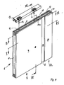
- Fig. L shows a perspective view of the two-shell telescopic element l, which is suspended on rollers la in a thick rail lb longitudinally displaceable.
- the telescopic element 1 has a wall part 8, on the support frame 9 of the rollers la and outer plates 4 on both sides are attached.
- the telescopic part 20 has cover plates 24 which partially overlap the cover plates 4 of the wall part 8 during the telescopic movement and run in corresponding, external, parallel running planes when the telescopic part 20 moves horizontally.
- an upper and a lower horizontal sealing strip 10 are provided, which have a sealing strip edge section 12 coupled to the telescopic part 20 and consequently participating in the movement of the telescopic part.
- An actuating mechanism (not shown) is arranged between the cover plates 4 of the wall part 8 and the cover plates 24 of the telescopic part 20 and moves both the telescopic part 20 and the sealing strips 10 by means of a crank which can be attached from the outside (for example at point 5).
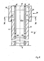
- Fig. 2 shows a horizontal section along the line II-II of Fig. 1
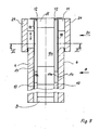
- Fig. 3 shows a vertical section along the line III-III of Fig. 1 or 2.
- Figs. 2 and 3 is produced when extending of the telescopic part 20 in this known telescopic element l between the cover plates 24 and the sealing strip edge section l2 a butt joint l3 on both sides, through which sound waves can pass undisturbed.
- another butt joint l3 is created at the joint between the sealing strips l0 and the sealing strip edge sections l2, which also allows undisturbed passage of sound waves.
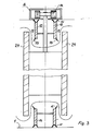
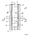
- FIGS. 1, 2 and 3 show different views of a telescopic element 1 according to the invention, namely in a perspective overall view (FIG. 4) in a first horizontal section along the line VV (FIG. 5), a second horizontal section along the line VI-VI (FIG. 6) and a vertical section along the line VII-VII (Fig. 7).
- FIGS. 1, 2 and 3 correspond to FIGS. 1, 2 and 3, so that the differences from the known telescopic element 1 are clearly recognizable.
- a cover plate 4 is screwed onto a support frame 9 of the wall part 8 on both sides. Between the cover plates 4, a sealing strip 10 is arranged at the upper and lower edge of the wall part 8, which can be extended electrically or mechanically against the floor or the ceiling by means of an actuation mechanism (not shown).
- a telescopic part 20 On the right edge of the telescopic element 1, a telescopic part 20 is arranged, which has a vertical edge beam 11, which can be extended horizontally and on both Sides each cover plate 24 holds.
- the sealing strips l0 have a sealing strip edge section l2 projecting between the cover plates 24 of the telescopic part 20, which is coupled to the telescopic part 20 and can be telescoped together with it.
- the cover plates 4 of the wall part 8 are flush with the cover plates 24 of the telescopic part 20.
- Thin intermediate plates 18 are screwed against the inner surface of the cover plates 24, the free end of which protrudes behind the cover plates 4 of the wall part 8 that the cover plates 4 can be engaged even when the telescopic part 20 is fully extended.
- the adjacent vertical edges of the cover plates 4, 24 form a butt joint when the telescopic part 20 is retracted.
- shadow gaps with the width of the telescopic stroke are formed at the abutment of the cover plates 4, 24, which reveal the intermediate plates 18.
- the intermediate plates 18 run over the entire height of the cover plates 4, 24 and consist of thin material, e.g. Sheet. This ensures that the gap l4 behind the cover plates 4, which must be present for receiving the intermediate plates l8, is very narrow.
- the sealing strips l0 and the sealing strip edge sections l2 have sealing lips l5 which bear outward against the cover plates 4, 24, cf. Fig. 7, so that no free sound path is formed from one side of the telescopic element 1 to the other side.
- the upper and lower telescopic sealing strip edge section l2 is slidably mounted on a rail l5a, which is firmly connected to the associated sealing strip l0.
- the sealing strip edge section l2 is e.g. coupled at its front end to the edge beam 11 of the telescopic part 20.
- the cover elements 16 are e.g. screwed onto the outer surface of the sealing strip edge section l2 and overlap the sealing strips l0.
- the wall thickness of the cover elements l6 corresponds to the wall thickness of the intermediate plates l8, so that the cover elements l6 can be accommodated in the gap l4 created by the intermediate plates l8.
- the cover elements l6 have approximately the height of the sealing strip l0 and each have their own sealing lip l7 on their upper and lower horizontal edge in order to implement a mechanical lock against direct sound passage in the area of the joint l3.
- the cover plates 24 of the telescopic part 20 are arranged such that they cover the cover plates 4 of the wall part 8 at least during a section of the telescopic part motion overlap.
- intermediate plates l8 are fastened, which with their free ends engage the cover plates 4 of the wall part 8 on the inside and extend over the entire height of the cover plates 4, 24, cf. . 9 to ll.
- the sealing strips l0 and the sealing strip edge sections l2 in turn have sealing lips l5, which bear against the intermediate plates l3 and prevent undisturbed passage of sound from one side of the telescopic element to the other side of the telescopic element. Since the joint l3a between the sealing strip l0 and the sealing strip edge section l2 lies in the region of the wall part 8, additional cover elements l6 are also provided in this embodiment, which have the height of the sealing strips l0, are screwed onto the sealing strips l0 or the sealing strip edge sections l2 and overlap the joint l3a that forms during telescoping. As a result, the joint l3a is blocked against direct sound passage.
- the intermediate plates 18 and the cover elements 16 have a small wall thickness in comparison to the cover plates 4, 24.
Landscapes
- Engineering & Computer Science (AREA)
- Architecture (AREA)
- Physics & Mathematics (AREA)
- Electromagnetism (AREA)
- Civil Engineering (AREA)
- Structural Engineering (AREA)
- Building Environments (AREA)
- Specific Sealing Or Ventilating Devices For Doors And Windows (AREA)
- Extensible Doors And Revolving Doors (AREA)
Abstract
Es wird ein zweischaliges Teleskopelement (1) einer beweglichen Trennwand angegeben, das zwei äußere Deckplatten (4) auf dem Tragrahmen (9) eines Wandteils (8) enthält, zwischen denen am oberen und/oder unteren Rand Dichtleisten (10) geführt und gegen die Decke bzw. den Boden ausfahrbar sind. Ein randseitiges Teleskopteil (20) besitzt einen vertikalen Randholm (11), an dem ebenfalls Deckplatten (24) befestigt sind, welche die Deckplatten des Wandteils überlappen oder flächenbündig fortsetzen. Die Dichtleisten (10) besitzen einen zwischen die Deckplatten (24) des Teleskopteils hineinragenden Randabschnitt (12), der mit dem Teleskopteil (20) zusammen horizontal verschiebbar ist. Um eine verbesserte Schalldämmung zu erzielen, sind Zwischenplatten (18) vorgesehen, welche die Deckplatten (4, 24) des Wandteils und des Teleskopteils hintergreifen. 
Description
Die Erfindung betrifft ein zweischaliges Teleskopelement einer beweglichen Trennwand, mit einem Wandteil, welches Deckplatten auf beiden Seiten eines Tragrahmens enthält und mit Laufrollen in deckenfesten Laufschienen verfahrbar abgehängt ist, mit einem vom Wandteil horizontal ausfahrbaren Teleskopteil, mit außenliegenden Deckplatten, mit Dichtleisten am oberen und/oder unteren Rand des Wandteils, die zwischen den Deckplatten gegen die Decke bzw. den Boden ausfahrbar sind, und mit einem Dichtleisten-Randabschnitt, der zwischen die Deckplatten des Teleskopteils hineinragt und mit dem Teleskopteil gekoppelt ist.The invention relates to a double-shell telescopic element of a movable partition, with a wall part which contains cover plates on both sides of a supporting frame and is movably suspended with rollers in ceiling-fixed tracks, with a telescopic part which can be extended horizontally from the wall part, with external cover plates, with sealing strips on the top and / or lower edge of the wall part, which can be extended between the cover plates against the ceiling or the floor, and with a sealing strip edge section which projects between the cover plates of the telescopic part and is coupled to the telescopic part.
Bewegliche, glatte Trennwände bestehen aus mehreren einzelnen Wandelementen, die mittels Laufrollen in deckenfesten Laufschienen verfahrbar abgehängt sind. Zum Öffnen bzw. Beseitigen der Trennwand werden die einzelnen Wandelemente aus einer Verriegelung gelöst und längs der Laufschiene in einen Staubereich verfahren und parallel zueinander gestaut. Zum Schließen der Wand werden die Wandelemente dicht aneinandergereiht in eine Ebene gebracht und durch Dichtleisten verspannt, welche zwischen den Verkleidungsplatten der Wandelemente gegen die Decke und/oder den Boden ausgefahren werden. Vorgeshen ist ferner an dem einen oder anderen seitlichen Ende der Trennwand ein Teleskopelement mit einem randseitigen Teleskopteil, welches beim Schließen der Wand horizontal gegen eine feststehende Gebäudewand o. dgl. ausfahrbar ist, um die Wandelemente auch horizontal gegeneinander zu verspannen und die verfügbare lichte Weite der betreffenden Gebäudeöffnung spaltfrei mit der Trennwand zu verschließen.Movable, smooth partitions consist of several individual wall elements, which are suspended by rollers in ceiling-fixed rails. To open or remove the partition, the individual wall elements are released from a lock and moved along the running rail into a storage area and stowed parallel to one another. To close the wall, the wall elements are brought close together in one plane and braced by sealing strips, which are extended between the cladding panels of the wall elements against the ceiling and / or the floor. Also provided at one or the other lateral end of the partition is a telescopic element with an edge-side telescopic part, which can be extended horizontally against a fixed building wall or the like when the wall is closed to also clamp the wall elements horizontally against each other and to close the available internal width of the building opening in question without a gap with the partition.
Die bekannten Teleskopelemente besitzen an ihrem Teleskopteil äußere Deckplatten, welche die Deckplatten des Wandteils sowohl in eingefahrener als auch ausgefahrener Stellung überlappen, um einen optisch sauberen Trennwand-Abschluß zu verwirklichen. Da die Deckplatten des Teleskopteils die Deckplatten des Wandteils überlappen, sind die Teleskopteil-Deckplatten von dem Dichtleisten-Randabschnitt, welcher mit dem Teleskopteil gekoppelt ist, um die Stärke der Wandteil-Deckplatten beabstandet. Wird das Teleskopteil ausgefahren, so entsteht folglich zwischen den Deckplatten des Teleskopteils ein Zwischenraum, der in eingefahrener Stellung des Teleskopteils von den Deckplatten des Wandteils ausgefüllt ist. Der sich beim Ausfahren des Teleskopteils bildende Zwischenraum hat zur Folge, daß die akustische Dämmung der Trennwand an dieser Stelle verringert wird, weil Schallwellen dann von diesem Zwischenraum unter dem Dichtleisten-Randabschitt hindurch ungestört von der einen zur anderen Seite des Teleskopelements gelangen können.The known telescopic elements have on their telescopic part outer cover plates which overlap the cover plates of the wall part both in the retracted and extended positions in order to achieve a visually clean partition closure. Since the cover plates of the telescopic part overlap the cover plates of the wall part, the telescope part cover plates are spaced apart from the sealing strip edge section which is coupled to the telescopic part by the thickness of the wall part cover plates. If the telescopic part is extended, there is consequently an intermediate space between the cover plates of the telescopic part, which is filled in by the cover plates of the wall part in the retracted position of the telescopic part. The space which forms when the telescopic part is extended has the consequence that the acoustic insulation of the partition wall is reduced at this point, because sound waves can then pass undisturbed from this space under the sealing strip edge section from one side to the other of the telescopic element.
Aufgabe der Erfindung ist es demgegenüber, ein zweischaliges Teleskopelement der eingangs genannten Art derart weiterzubilden, daß eine verbesserte Schalldämmung bei optisch ansprechendem Aussehen verwirklicht wird.In contrast, the object of the invention is to develop a two-shell telescopic element of the type mentioned at the outset in such a way that improved sound insulation with an optically appealing appearance is achieved.
Diese Aufgabe wird erfindungsgemäß dadurch gelöst, daß relativ dünne Zwischenplatten vorgesehen sind, welche die Deckplatten des Wandteils und die Deckplatten des Teleskopteils in ihren Stoß- oder Überlappungsbereich hintergreifen.This object is achieved in that relatively thin intermediate plates are provided which engage behind the cover plates of the wall part and the cover plates of the telescopic part in their abutment or overlap area.
Die Vorteile der Erfindung liegen insbesondere darin, daß die beim Ausfahren des Teleskopteils zwischen den Deckplatten des Wandteils und den Deckplatten des Teleskopteils entstehenden Fugen durch innenliegende Zwischenplatten im wesentlichen über die gesamte vertikale Höhe des Teleskopelements abgedeckt sind. Da die Zwischenplatten eine gegenüber den Deckplatten erheblich reduzierte Wandstärke besitzen und außerdem aus einem akustisch ausreichend dämmenden Material bestehen, wird beim Ausfahren des Teleskopteils zwischen dessen Deckplatten und dem ebenfalls teleskopierenden Dichtleisten-Randabschnitt nur noch ein vergleichsweise schmaler Zwischenraum erzeugt, welcher der Wandstärke der Deckplatten entspricht. Diese schmalen Spalte werden von auswärtsspreizenden Gummilippen abgedeckt, welche sich an den Dichtleisten befinden, so daß der freie Durchtritt von Schallwellen verhindert ist.The advantages of the invention lie in particular in the fact that the joints formed when the telescopic part is extended between the cover plates of the wall part and the cover plates of the telescopic part are covered by internal intermediate plates essentially over the entire vertical height of the telescopic element. Since the intermediate plates have a wall thickness that is considerably reduced compared to the cover plates and also consist of an acoustically sufficiently insulating material, when the telescopic part is extended, only a comparatively narrow space is generated between the cover plates and the telescoping sealing strip edge section, which corresponds to the wall thickness of the cover plates . These narrow gaps are covered by outward-spreading rubber lips, which are located on the sealing strips, so that the free passage of sound waves is prevented.
Gemäß einer besonders bevorzugten Ausführungsform der Erfindung fluchten die Deckplatten des Wandteils und die Deckplatten des Teleskopteils auf Stoß, und die Zwischenplatten sind auf den Innenflächen der Deckplatten des Wandteils oder des Teleskopteils befestigt und greifen mit ihrem freien Ende hinter die Deckplatten des Teleskopteils bzw. des Wandteils und bilden auf diese Weise die Basis der beim Ausfahren des Teleskopteils entstehenden Schattenfuge, welche gleich oder größer als der Teleskopierhub ist. Diese Ausführungsform besitzt den Vorteil, daß auch die Deckplatten des Teleskopteils mit den übrigen Deckplatten der Trennwand fluchten, so daß eine optisch ansprechende ebene Gestaltung der gesamten Trennwand entsteht.According to a particularly preferred embodiment of the invention, the cover plates of the wall part and the cover plates of the telescopic part are flush, and the intermediate plates are fastened to the inner surfaces of the cover plates of the wall part or the telescopic part and engage with their free end behind the cover plates of the telescopic part or the wall part and thus form the basis of the when extending of the telescopic part resulting shadow gap, which is equal to or larger than the telescopic stroke. This embodiment has the advantage that the cover plates of the telescopic part are aligned with the other cover plates of the partition, so that a visually appealing flat design of the entire partition is created.
Alternativ ist es möglich, daß die Deckplatten des Teleskopteils die Deckplatten des Wandteils sowohl im eingefahrenen als auch im ausgefahrenen Zustand überlappen. Bei dieser Ausführungsform sind die Zwischenplatten am freien Vertikalrand des Teleskopteils befestigt und ragen mit ihrem freien Ende hinter die Deckplatten des Wandteils. Beim Ausfahren des Teleskopteils entsteht dann ein Freiraum zwischen den Deckplatten des Teleskopteils und den Zwischenplatten; der Schalldurchgang wird jedoch durch die Zwischenplatten wirksam unterbunden, welche gegen die Dichtleisten und Dichtleisten-Randabschnitten anliegen.Alternatively, it is possible that the cover plates of the telescopic part overlap the cover plates of the wall part both in the retracted and in the extended state. In this embodiment, the intermediate plates are attached to the free vertical edge of the telescopic part and project with their free end behind the cover plates of the wall part. When the telescopic part is extended, there is then a free space between the cover plates of the telescopic part and the intermediate plates; however, the passage of sound is effectively prevented by the intermediate plates which bear against the sealing strips and sealing strip edge sections.
Gemäß einer weiteren besonders bevorzugten Ausführungsform der Erfindung sind die Deckplatten des Teleskopteils mittels einer geeigneten Mechanik (gemäß der gleichzeitig eingereichten Patentanmeldung EP........) derart geführt, daß sie die Deckplatten des Wandteils während der Teleskopierbewegung überlappen und bei Erreichen der ausgefahrenen Stellung von den Verkleidungsplatten des Wandteils freikommen und dann - senkrecht zu den Plattenebenen - in eine mit den Deckplatten des Wandteils flächenbündig fluchtende Stellung übergehen. Bei dieser Ausführungsform der Erfindung sind die Zwischenplatten innenliegend an die Deckplatten des Wandteils angesetzt und ragen mit ihrem freien Ende ausreichend lang in das Teleskopteil hinein, um die Basis für die gewünschte oder entstehende Schattenfuge zu bilden.According to a further particularly preferred embodiment of the invention, the cover plates of the telescopic part are guided by means of a suitable mechanism (according to the simultaneously filed patent application EP ........) such that they overlap the cover plates of the wall part during the telescopic movement and when the come out of the extended position from the cladding panels of the wall section and then - perpendicular to the board levels - move into a position flush with the cover panels of the wall section. In this embodiment of the invention, the intermediate plates internally attached to the cover plates of the wall part and with their free end protrude long enough into the telescopic part to form the basis for the desired or emerging shadow gap.
Gemäß einer Ausführungsform der Erfindung fluchten die Dichtleisten des Wandteils mit den Dichtleisten-Randabschnitten des Teleskopteils auf Stoß. Erfindungsgemäß sind dann im Bereich dieser Stoßstelle zusätzliche Abdeckelemente an den Dichtleisten vorgesehen, deren vertikale Höhe etwa gleich der Höhe der Dichtleisten ist, so daß auch an diesen Stoßstellen beim Ausfahren des Teleskopteils ein direkter Pfad für den Schallwellendurchtritt verhindert wird. Alternativ ist es möglich, daß die Dichtleisten-Randabschnitte die Dichtleisten teleskopierend überlappen, wodurch ebenfalls ein freier Pfad für den Schalldurchtritt verhindert wird. Die Stoß- oder Überlappungsbereiche zwischen Dichtleisten und Dichtleisten-Randabschnitten können gegen die Stoß- oder Überlappungsbereiche der Deckplatten versetzt sein. Die Abdeckelemente zwischen den auf Stoß fluchtenden Dichtleisten und Dichtleisten-Randabschnitten lassen sich dann vorteilhafterweise außenliegend entweder auf die Dichtleiste oder den Dichtleisten-Randabschnitt aufsetzen und liegen dann in einer Ebene fluchtend mit den Zwischenplatten.According to one embodiment of the invention, the sealing strips of the wall part are flush with the sealing strip edge sections of the telescopic part. According to the invention, additional covering elements are then provided on the sealing strips in the area of this joint, the vertical height of which is approximately equal to the height of the sealing strips, so that a direct path for the passage of sound waves is prevented at these joints when the telescopic part is extended. Alternatively, it is possible that the sealing strip edge sections telescopically overlap the sealing strips, which likewise prevents a clear path for the passage of sound. The abutting or overlapping areas between sealing strips and sealing strip edge sections can be offset against the abutting or overlapping areas of the cover plates. The cover elements between the sealing strips and sealing strip edge sections that are aligned with one another can then advantageously be placed on the outside either on the sealing strip or the sealing strip edge section and are then flush with the intermediate plates.
Bevorzugt sind zwischen den Dichtleisten, den Dichtleisten-Randabschnitten und den Deckplatten elastische Dichtlippen angeordnet.Elastic sealing lips are preferably arranged between the sealing strips, the sealing strip edge sections and the cover plates.
Vorteilhafte Weiterbildungen der Erfindung sind durch die Merkmale der Unteransprüche gekennzeichnet.Advantageous developments of the invention are characterized by the features of the subclaims.
Im folgenden werden Ausführungsbeispiele der Erfindung anhand der Zeichnung näher erläutert. Es zeigen:
- Fig. l eine perspektivische Ansicht eines bekannten Teleskopelements;
- Fig. 2 einen Horizontalschnitt längs der Linie II-II der Fig. l;
- Fig. 3 einen Vertikalschnitt längs der Linie III-III der Fig. l oder 2;
- Fig. 4 eine perspektivische Ansicht einer ersten Ausführungsform des erfindungsgemäßen Teleskopelements;
- Fig. 5 einen Horizontalschnitt längs der Linie V-V der Fig. 4;
- Fig. 6 einen Horizontalschnitt längs der Linie VI-VI der Fig. 4;
- Fig. 7 einen Vertikalschnitt längs der Linie VII-VII der Fig. 4 bzw. 6;
- Fig. 8 eine perspektivische Ansicht einer zweiten Ausführungsform des erfindungsgemäßen Teleskopelements;
- Fig. 9 einen Horizontalschnitt längs der Linie IX-IX der Fig. 8;
- Fig. l0 einen Horizontalschnitt längs der Linie X-X der Fig. 8; und
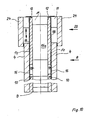
- Fig. ll einen Vertikalschnitt längs der Linie XI-XI der Fig. 8.
- Fig. L is a perspective view of a known telescopic element;
- Fig. 2 is a horizontal section along the line II-II of Fig. 1;
- 3 shows a vertical section along the line III-III of FIG. 1 or 2;
- 4 shows a perspective view of a first embodiment of the telescopic element according to the invention;
- Fig. 5 is a horizontal section along the line VV of Fig. 4;
- Fig. 6 is a horizontal section along the line VI-VI of Fig. 4;
- Figure 7 is a vertical section along the line VII-VII of Figures 4 and 6;
- 8 shows a perspective view of a second embodiment of the telescopic element according to the invention;
- Fig. 9 is a horizontal section along the line IX-IX of Fig. 8;
- Fig. 10 is a horizontal section along the line XX of Fig. 8; and
- Fig. Ll is a vertical section along the line XI-XI of Fig. 8th
Die Fig. l zeigt eine perspektivische Ansicht des zweischaligen Teleskopelements l, welches an Laufrollen la in einer dicken Schiene lb längsverschiebbar aufgehängt ist. Das Teleskopelement l besitzt ein Wandteil 8, an dessen Tragrahmen 9 die Laufrollen la und beidseitig außenliegende Deckplatten 4 befestigt sind. An einer Vertikalkante des Wandteils 8 ist ein Teleskopteil 20 vorgesehen, welches sich über die gesamte Höhe des Wandteils 8 erstreckt und von diesem horizontal einen vorgegebenen Hub ausfahrbar ist. Das Teleskopteil 20 besitzt Deckplatten 24, welche die Deckplatten 4 des Wandteils 8 während der Teleskopierbewegung teilweise überlappen und in entsprechenden, außenliegenden, parallelen Laufebenen laufen, wenn sich das Teleskopteil 20 horizontal bewegt. Zwischen den Deckplatten 4 des Wandteils 8 und den Deckplatten 24 des Teleskopteils 20 sind je eine obere und eine untere horizontale Dichtleiste l0 vorgesehen, welche einen mit dem Teleskopteil 20 gekoppelten und folglich die Teleskopteil-Bewegung mitmachenden Dichtleisten-Randabschnitt l2 besitzen. Zwischen den Deckplatten 4 des Wandteils 8 und den Deckplatten 24 des Teleskopteils 20 ist eine Betätigungsmechanik angeordnet (nicht dargestellt) welche mittels einer von außen (z.B. an der Stelle 5) ansetzbaren Kurbel sowohl das Teleskopteil 20 als auch die Dichtleisten l0 verfährt.Fig. L shows a perspective view of the two-shell telescopic element l, which is suspended on rollers la in a thick rail lb longitudinally displaceable. The
Fig. 2 zeigt einen Horizontalschnitt längs der Linie II-II der Fig. l, und Fig. 3 zeigt einen Vertikalschnitt längs der Linie III-III der Fig. l oder 2. Wie den Fig. 2 und 3 entnehmbar ist, entsteht beim Ausfahren des Teleskopteils 20 bei diesem bekannten Teleskopelement l zwischen den Deckplatten 24 und dem Dichtleisten-Randabschnitt l2 auf beiden Seiten eine Stoßfuge l3, durch welche Schallwellen ungestört hindurchtreten können. Außerdem entsteht an der Stoßstelle zwischen den Dichtleisten l0 und den Dichtleisten-Randabschnitten l2 eine weitere Stoßfuge l3, welche ebenfalls ungestörten Durchgang von Schallwellen zuläßt.Fig. 2 shows a horizontal section along the line II-II of Fig. 1, and Fig. 3 shows a vertical section along the line III-III of Fig. 1 or 2. As can be seen in Figs. 2 and 3, is produced when extending of the
Die Fig. 4 bis 7 zeigen verschiedene Ansichten eines erfindungsgemäßen Teleskopelements l, und zwar in perspektivischer Gesamtansicht (Fig. 4) in einem ersten Horizontalschnitt längs der Linie V-V (Fig. 5), einem zweiten Horizontalschnitt längs der Linie VI-VI (Fig. 6) und einem Vertikalschnitt längs der Linie VII-VII (Fig. 7). Die Fig. 4, 5 und 7 entsprechen den Fig. l, 2 und 3, so daß die Unterschiede zu dem bekannten Teleskopelement l deutlich erkennbar sind. Auf einem Tragrahmen 9 des Wandteils 8 ist auf beiden Seiten je eine Deckplatte 4 aufgeschraubt. Zwischen den Deckplatten 4 ist am oberen und unteren Rand des Wandteils 8 je eine Dichtleiste l0 angeordnet, die mittels einer - nicht dargestellten - Betätigungsmechanik elektrisch oder mechanisch gegen den Boden oder die Decke ausfahrbar sind. Am rechten Rand des Teleskopelements l ist ein Teleskopteil 20 angeordnet, welches einen vertikalen Randholm ll besitzt, der horizontal ausfahrbar ist und auf beiden Seiten je eine Deckplatte 24 hält. Die Dichtleisten l0 besitzen einen zwischen die Deckplatten 24 des Teleskopteils 20 hineinragenden Dichtleisten-Randabschnitt l2, der mit dem Teleskopteil 20 gekoppelt und mit diesem zusammen teleskopierbar ist.4 to 7 show different views of a
In der Ausführungsform gemäß den Fig. 4 bis 7 fluchten die Deckplatten 4 des Wandteils 8 flächenbündig mit den Deckplatten 24 des Teleskopteils 20. Gegen die Innenfläche der Deckplatten 24 sind dünne Zwischenplatten l8 angeschraubt, deren freies Ende soweit hinter die Deckplatten 4 des Wandteils 8 ragt, daß die Deckplatten 4 auch noch bei vollständig ausgefahrenem Teleskopteil 20 hintergriffen werden. Die einander benachbarten Vertikalkanten der Deckplatten 4, 24 bilden bei eingefahrenem Teleskopteil 20 einen Stumpfstoß. Bei ausgefahrenem Teleskopteil 20 bilden sich an der Stoßstelle der Deckplatten 4, 24 Schattenfugen mit der Breite des Teleskopierhubes, welche die Zwischenplatten l8 zum Vorschein kommen lassen.In the embodiment according to FIGS. 4 to 7, the
Die Zwischenplatten l8 verlaufen über die gesamte Höhe der Deckplatten 4, 24 und bestehen aus dünnem Material, z.B. Blech. Dadurch ist sichergestellt, daß der Spalt l4 hinter den Deckplatten 4, der zur Aufnahme der Zwischenplatten l8 vorhanden sein muß, sehr schmal ist.The
Die Dichtleisten l0 und die Dichtleisten-Randabschnitte l2 besitzen nach außen gegen die Deckplatten 4, 24 anliegende Dichtlippen l5, vgl. Fig. 7, so daß sich von der einen Seite des Teleskopelements l zur anderen Seite kein freier Schallweg ausbildet.The sealing strips l0 and the sealing strip edge sections l2 have sealing lips l5 which bear outward against the
Der obere und der untere teleskopierbare Dichtleisten-Randabschnitt l2 ist auf je einer Schiene l5a verschiebbar gelagert, die mit der zugehörigen Dichtleiste l0 fest verbunden ist. Der Dichtleisten-Randabschnitt l2 ist z.B. an seinem vorderen Ende mit dem Randholm ll des Teleskopteils 20 gekoppelt. Zwischen der Dichtleiste l0 und dem teleskopierbaren Dichtleisten-Randabschnitt l2 ist eine Stoßstelle l3a vorhanden, die gegenüber der Stoßstelle 6 der Deckplatten 4, 24 versetzt ist und mit zusätzlichen Abdeckelementen l6 abgedeckt ist, vgl. Fig. 6 oder 7. Die Abdeckelemente l6 sind z.B. auf der Außenfläche des Dichtleisten-Randabschnitts l2 aufgeschraubt und überlappen die Dichtleisten l0. Die Wandstärke der Abdeckelemente l6 entspricht der Wandstärke der Zwischenplatten l8, so daß die Abdeckelemente l6 in den von den Zwischenplatten l8 erzeugten Spalt l4 untergebracht werden können. Die Abdeckelemente l6 besitzen etwa die Höhe der Dichtleiste l0 und weisen an ihrer oberen und unteren Horizontalkante je eine eigene Dichtlippe l7 auf, um auch im Bereich der Stoßstelle l3 eine mechanische Sperre gegen direkten Schalldurchtritt zu verwirklichen.The upper and lower telescopic sealing strip edge section l2 is slidably mounted on a rail l5a, which is firmly connected to the associated sealing strip l0. The sealing strip edge section l2 is e.g. coupled at its front end to the
Die Fig. 8 bis ll zeigen ein zweites erfindungsgemäßes Teleskopelement, dessen Aufbau weitgehend dem in den Fig. 4 bis 7 dargestellten Teleskoptelement l entspricht, wobei gleiche Teile mit denselben Bezugszeichen versehen sind. Abweichend vom Teleskopelement der Fig. 4 bis 7 sind bei dieser zweiten Ausführungsform die Deckplatten 24 des Teleskopteils 20 so angeordnet, daß sie die Deckplatten 4 des Wandteils 8 zumindest während eines Abschnitts der Teleskopierbe wegung überlappen. Am freien Vertikalrand des Teleskopteils 20, und zwar entweder am Randholm oder am Dichtleisten-Randabschnitt l2 sind Zwischenplatten l8 befestigt, die mit ihren freien Enden die Deckplatten 4 des Wandteils 8 innenliegend hingreifen und sich über die gesamte Höhe der Deckplatten 4, 24 erstrecken, vgl. Fig. 9 bis ll. Die Dichtleisten l0 und die Dichtleisten-Randabschnitte l2 besitzen wiederum Dichtlippen l5, welche gegen die Zwischenplatten l3 anliegen und einen ungestörten Schalldurchtritt von der einen Seite des Teleskopelements zur anderen Seite des Teleskopelements verhindern. Da die Stoßstelle l3a zwischen Dichtleiste l0 und Dichtleisten-Randabschnitt l2 im Bereich des Wandteils 8 liegt, sind auch bei dieser Ausführungsform zusätzliche Abdeckelemente l6 vorgesehen, die die Höhe der Dichtleisten l0 besitzen, an den Dichtleisten l0 oder den Dichtleisten-Randabschnitten l2 angeschraubt sind und die sich beim Teleskopieren bildende Stoßstelle l3a überlappen. Dadurch wird auch die Stoßstelle l3a gegen direkten Schalldurchtritt gesperrt.8 to 11 show a second telescopic element according to the invention, the structure of which largely corresponds to the
Die Zwischenplatten l8 und die Abdeckelemente l6 besitzen im Vergleich zu den Deckplatten 4, 24 eine geringe Wandstärke.The
Claims (10)
mit Dichtleisten am oberen und/oder unteren Rand des Wandteils, die zwischen den Deckplatten gegen die Decke bzw. den Boden ausfahrbar sind,
und mit einem Dichtleisten-Randabschnitt, der zwischen die Deckplatten des Teleskopteils hineinragt und mit dem Teleskopteil gekoppelt ist,
gekennzeichnet durch
Zwischenplatten (l8), welche die Deckplatten (4) des Wandteils (8) und die Deckplatten (24) des Teleskopteils (20) in ihrem Stoß- oder Überlappungsbereich hintergreifen.1.Two-shell telescopic element of a movable partition, with a wall part, which contains cover plates on both sides of a support frame and is movably suspended with rollers in ceiling-fixed tracks, with a telescopic part that can be extended horizontally from the wall part, with external cover plates,
with sealing strips on the upper and / or lower edge of the wall part, which can be extended between the cover plates against the ceiling or the floor,
and with a sealing strip edge section which projects between the cover plates of the telescopic part and is coupled to the telescopic part,
marked by
Intermediate plates (18) which engage behind the cover plates (4) of the wall part (8) and the cover plates (24) of the telescopic part (20) in their abutting or overlapping area.
Applications Claiming Priority (2)
| Application Number | Priority Date | Filing Date | Title |
|---|---|---|---|
| DE19863619392 DE3619392A1 (en) | 1986-06-09 | 1986-06-09 | TWO-TONE TELESCOPIC ELEMENT OF A MOVABLE PARTITION |
| DE3619392 | 1986-06-09 |
Publications (2)
| Publication Number | Publication Date |
|---|---|
| EP0249765A2 true EP0249765A2 (en) | 1987-12-23 |
| EP0249765A3 EP0249765A3 (en) | 1990-05-23 |
Family
ID=6302629
Family Applications (1)
| Application Number | Title | Priority Date | Filing Date |
|---|---|---|---|
| EP87107437A Withdrawn EP0249765A3 (en) | 1986-06-09 | 1987-05-22 | Double wall telescopic element for a movable partition |
Country Status (5)
| Country | Link |
|---|---|
| US (1) | US4833840A (en) |
| EP (1) | EP0249765A3 (en) |
| JP (1) | JPH0781350B2 (en) |
| AU (1) | AU7404087A (en) |
| DE (1) | DE3619392A1 (en) |
Cited By (2)
| Publication number | Priority date | Publication date | Assignee | Title |
|---|---|---|---|---|
| GB2205336A (en) * | 1987-06-02 | 1988-12-07 | Michael Sacks | Bullet resistant partitions |
| DE202009014565U1 (en) | 2009-10-28 | 2010-02-04 | Dorma Gmbh + Co. Kg | Mobile partition with wall connection element |
Families Citing this family (27)
| Publication number | Priority date | Publication date | Assignee | Title |
|---|---|---|---|---|
| US5511348A (en) | 1990-02-14 | 1996-04-30 | Steelcase Inc. | Furniture system |
| US6134844A (en) | 1990-02-14 | 2000-10-24 | Steelcase Inc. | Method and apparatus for displaying information |
| US6170200B1 (en) | 1990-02-14 | 2001-01-09 | Steelcase Development Inc. | Furniture system |
| US6003275A (en) | 1990-02-14 | 1999-12-21 | Steelcase Development Inc. | Furniture system |
| US5873205A (en) * | 1990-11-28 | 1999-02-23 | Advantage Office Systems, Llc | Privacy panel for use with open office furniture systems |
| CA2101110A1 (en) * | 1992-07-23 | 1994-01-24 | Kenneth James Macquarrie | Expandable office panel |
| US5577348A (en) * | 1993-05-25 | 1996-11-26 | Rosconi Ag | Partition wall with sliding termination panel |
| CH689233A5 (en) * | 1996-05-07 | 1998-12-31 | Dorma Tuerautomatik Ag | sliding partition |
| US5791094A (en) * | 1997-01-09 | 1998-08-11 | Diverse Industries, Inc. | Movable wall for ball court |
| US5918422A (en) * | 1997-05-14 | 1999-07-06 | Bucher, Jr.; Robert Joseph | Open office panel system |
| US6058665A (en) * | 1998-03-10 | 2000-05-09 | Steelcase Development Inc. | Adjustable door and doorway construction |
| FR2791234B1 (en) * | 1999-03-24 | 2003-10-17 | Nicaise Gregoire | ADAPTABLE DEVICE FOR DELIMITATION AND LAYOUT OF SPACES AND VOLUMES |
| AUPQ297399A0 (en) * | 1999-09-20 | 1999-10-14 | Rapini Pty Ltd | Storage unit |
| AT4650U1 (en) * | 2000-10-05 | 2001-10-25 | Lenz Gmbh | FRAME PANEL SYSTEM FOR HANGING PANELS IN ROOMS |
| US7707790B2 (en) * | 2003-06-12 | 2010-05-04 | Steelcase Inc. | Office system |
| US7516624B2 (en) * | 2005-06-01 | 2009-04-14 | Weeth Frederic R | Cooling room |
| DE102005048157A1 (en) * | 2005-10-06 | 2007-04-19 | Dorma Gmbh + Co. Kg | Mobile partition |
| DE102005048155A1 (en) * | 2005-10-06 | 2007-04-19 | Dorma Gmbh + Co. Kg | Mobile partition |
| DE102008027821A1 (en) * | 2008-06-11 | 2009-12-17 | Dorma Gmbh + Co. Kg | Partition wall made of transparent wall elements |
| US20090313935A1 (en) * | 2008-06-24 | 2009-12-24 | Environmental Interiors, Inc. | High Impact, Moisture Resistant Wall Panel System |
| EP2224076B1 (en) * | 2009-02-27 | 2013-06-05 | M-T Patents GmbH | Stand |
| US8402699B2 (en) | 2010-07-14 | 2013-03-26 | Kimball International, Inc. | Sliding privacy door for partition systems |
| DE102015108663A1 (en) * | 2015-06-01 | 2016-12-01 | Dorma Deutschland Gmbh | partition element |
| US10041249B1 (en) * | 2015-07-31 | 2018-08-07 | Timothy Hebert | Adjustable barrier for partitioning a building space |
| US12054942B2 (en) | 2020-12-08 | 2024-08-06 | STARC Systems, Inc. | Temporary wall system with fire block protection |
| CN115012775A (en) * | 2022-05-18 | 2022-09-06 | 广东坚美建筑科技发展有限公司 | A movable door assembly and sealing door |
| US12305388B2 (en) | 2022-07-15 | 2025-05-20 | STARC Systems, Inc. | Cap for a temporary wall system providing fire barrier protection |
Family Cites Families (12)
| Publication number | Priority date | Publication date | Assignee | Title |
|---|---|---|---|---|
| US3341992A (en) * | 1964-10-07 | 1967-09-19 | Robert Haws Co | Portable room dividing panel |
| US3327439A (en) * | 1964-10-21 | 1967-06-27 | Ralph W Eatough | Wall panel locking actuator |
| US3638376A (en) * | 1970-01-05 | 1972-02-01 | Hough Mfg Corp | Portable partition |
| DE2438982C2 (en) * | 1974-08-14 | 1976-09-09 | Hueppe Justin Fa | MOVABLE PARTITION WALL MADE OF AT LEAST ONE ROOM-HIGH, TWO-PANELED WALL ELEMENT |
| US4014137A (en) * | 1976-03-08 | 1977-03-29 | Hough Manufacturing Corporation | Drop action panel arrangement for operable partitions |
| JPS5428411A (en) * | 1977-08-04 | 1979-03-03 | Kouji Unayama | Device for fixing room partition wall |
| DE2836126A1 (en) * | 1978-08-18 | 1980-02-28 | Vki Rheinhold & Mahla Ag | Double skinned partition wall attachment to main structure - involves U=profile with outside cladding strips, and H-profile with resilient strips |
| SU842162A1 (en) * | 1979-08-23 | 1981-06-30 | Ордена Трудового Красного Знамени Централь-Ный Научно-Исследовательский И Проектныйинститут Строительных Металлоконструкций"Цниипроектстальконструкция" | Made-up bar |
| CH658090A5 (en) * | 1982-11-16 | 1986-10-15 | Karl Haab | WALL ELEMENT WITH A SEALING DEVICE AND SEPARATING WALL. |
| US4462192A (en) * | 1982-06-01 | 1984-07-31 | American Standard, Inc. | Seal assembly |
| DE3239485A1 (en) * | 1982-10-25 | 1984-05-03 | Rüterbau GmbH, 3012 Langenhagen | U-shaped connection piece for wall elements |
| DE3425484A1 (en) * | 1984-07-11 | 1986-01-23 | aboplan Viol und Partner GmbH, 2903 Bad Zwischenahn | Removable partition consisting of wall elements and method of producing and dismantling the wall elements |
-
1986
- 1986-06-09 DE DE19863619392 patent/DE3619392A1/en active Granted
-
1987
- 1987-05-22 EP EP87107437A patent/EP0249765A3/en not_active Withdrawn
- 1987-06-08 JP JP62141635A patent/JPH0781350B2/en not_active Expired - Lifetime
- 1987-06-08 US US07/059,105 patent/US4833840A/en not_active Expired - Fee Related
- 1987-06-09 AU AU74040/87A patent/AU7404087A/en not_active Abandoned
Cited By (2)
| Publication number | Priority date | Publication date | Assignee | Title |
|---|---|---|---|---|
| GB2205336A (en) * | 1987-06-02 | 1988-12-07 | Michael Sacks | Bullet resistant partitions |
| DE202009014565U1 (en) | 2009-10-28 | 2010-02-04 | Dorma Gmbh + Co. Kg | Mobile partition with wall connection element |
Also Published As
| Publication number | Publication date |
|---|---|
| JPH0781350B2 (en) | 1995-08-30 |
| DE3619392A1 (en) | 1987-12-10 |
| DE3619392C2 (en) | 1988-07-28 |
| US4833840A (en) | 1989-05-30 |
| JPS6375239A (en) | 1988-04-05 |
| AU7404087A (en) | 1987-12-10 |
| EP0249765A3 (en) | 1990-05-23 |
Similar Documents
| Publication | Publication Date | Title |
|---|---|---|
| EP0249765A2 (en) | Double wall telescopic element for a movable partition | |
| EP0249066B1 (en) | Double wall telescopic element | |
| DE1555995A1 (en) | Shell construction | |
| DE202017103784U1 (en) | cover device | |
| DE1683009B2 (en) | Folding door with at least two panels | |
| DE2851549C2 (en) | Device for connecting formwork panels, in particular in the area of gradations in a building | |
| EP0185188B1 (en) | Cabin | |
| DE3420453A1 (en) | HOLDING DEVICE FOR METAL PROFILES TO BE COVERED IN TWO COLORS | |
| DE7901833U1 (en) | SLIDING DOOR WITH VERTICAL SEAL DEVICE | |
| DE2350343A1 (en) | FURNITURE UNIT FOR INSTALLATION IN A RIGHT ANGLE CORNER OF A ROOM | |
| DE2427997C2 (en) | Movable partition | |
| DE3913383C2 (en) | ||
| EP0085355B1 (en) | Device for the connection of air-channel elements provided with flange sections at their edges which form openings for corner angles | |
| DE2233059B2 (en) | Movable partition wall with at least one sound-absorbing partition wall element | |
| DE2533856C3 (en) | Fall | |
| DE2805973A1 (en) | DOOR IN PARTICULAR DOUBLE LEAF DOORS | |
| DE2924444C2 (en) | Frame for windows or doors, especially for basement windows | |
| DE2811676C2 (en) | Sliding door connection, especially for prefabricated partition walls | |
| DE3719829A1 (en) | Partition-wall unit having individual panel elements fitted together edge to edge | |
| DE1709319A1 (en) | Room divider | |
| DE3903756C1 (en) | Apparatus for securing the transportation path between a building and a vehicle by movable shielding walls | |
| DE2523851A1 (en) | Partition wall with panel, window or door - inwards lengthways projection and bolt-connected outwards projections on side supports | |
| DE2628923C3 (en) | Device for ventilating and ventilating a cold roof covered with large-format roof tiles | |
| DE2857046C2 (en) | Movable wall element | |
| DE2142606C3 (en) | Double-shell sound-absorbing interior partition and method for producing the same |
Legal Events
| Date | Code | Title | Description |
|---|---|---|---|
| PUAI | Public reference made under article 153(3) epc to a published international application that has entered the european phase |
Free format text: ORIGINAL CODE: 0009012 |
|
| AK | Designated contracting states |
Kind code of ref document: A2 Designated state(s): AT BE CH DE ES FR GB GR IT LI LU NL SE |
|
| RAP1 | Party data changed (applicant data changed or rights of an application transferred) |
Owner name: HUEPPE FORM SONNENSCHUTZ- UND RAUMTRENNSYSTEME GMB |
|
| PUAL | Search report despatched |
Free format text: ORIGINAL CODE: 0009013 |
|
| AK | Designated contracting states |
Kind code of ref document: A3 Designated state(s): AT BE CH DE ES FR GB GR IT LI LU NL SE |
|
| 17P | Request for examination filed |
Effective date: 19900711 |
|
| 17Q | First examination report despatched |
Effective date: 19910726 |
|
| STAA | Information on the status of an ep patent application or granted ep patent |
Free format text: STATUS: THE APPLICATION IS DEEMED TO BE WITHDRAWN |
|
| 18D | Application deemed to be withdrawn |
Effective date: 19920306 |
|
| RIN1 | Information on inventor provided before grant (corrected) |
Inventor name: SCHUESSLER, KARL Inventor name: PETERSEN, GERD, DIPL.-ING. Inventor name: KALISCHEWSKI,ROLF |