EP0248937B1 - Vorrichtung zur Herstellung von einzelnen Blöcken aus Polyurethanschaum - Google Patents
Vorrichtung zur Herstellung von einzelnen Blöcken aus Polyurethanschaum Download PDFInfo
- Publication number
- EP0248937B1 EP0248937B1 EP86108124A EP86108124A EP0248937B1 EP 0248937 B1 EP0248937 B1 EP 0248937B1 EP 86108124 A EP86108124 A EP 86108124A EP 86108124 A EP86108124 A EP 86108124A EP 0248937 B1 EP0248937 B1 EP 0248937B1
- Authority
- EP
- European Patent Office
- Prior art keywords
- tank
- foam
- feed solution
- stirring tank
- polyurethane foam
- Prior art date
- Legal status (The legal status is an assumption and is not a legal conclusion. Google has not performed a legal analysis and makes no representation as to the accuracy of the status listed.)
- Expired
Links
- 229920005830 Polyurethane Foam Polymers 0.000 title claims abstract description 38
- 239000011496 polyurethane foam Substances 0.000 title claims abstract description 38
- 238000004519 manufacturing process Methods 0.000 title claims abstract description 24
- 238000003756 stirring Methods 0.000 claims abstract description 57
- 239000012527 feed solution Substances 0.000 claims abstract description 38
- 239000002904 solvent Substances 0.000 claims abstract description 12
- 238000005406 washing Methods 0.000 claims abstract description 8
- 239000006260 foam Substances 0.000 claims description 51
- JOYRKODLDBILNP-UHFFFAOYSA-N Ethyl urethane Chemical compound CCOC(N)=O JOYRKODLDBILNP-UHFFFAOYSA-N 0.000 claims description 6
- 239000000203 mixture Substances 0.000 claims description 2
- 239000002994 raw material Substances 0.000 abstract description 4
- 229920002635 polyurethane Polymers 0.000 abstract description 2
- 239000004814 polyurethane Substances 0.000 abstract description 2
- 238000000034 method Methods 0.000 description 7
- 239000012948 isocyanate Substances 0.000 description 6
- 150000002513 isocyanates Chemical class 0.000 description 6
- 239000000463 material Substances 0.000 description 4
- 239000003054 catalyst Substances 0.000 description 2
- 239000003795 chemical substances by application Substances 0.000 description 2
- 238000004140 cleaning Methods 0.000 description 2
- 238000007599 discharging Methods 0.000 description 2
- 238000005187 foaming Methods 0.000 description 2
- 238000009434 installation Methods 0.000 description 2
- 229920005862 polyol Polymers 0.000 description 2
- 150000003077 polyols Chemical class 0.000 description 2
- 239000011550 stock solution Substances 0.000 description 2
- 238000010923 batch production Methods 0.000 description 1
- 238000007664 blowing Methods 0.000 description 1
- 238000011437 continuous method Methods 0.000 description 1
- 238000010924 continuous production Methods 0.000 description 1
- 230000007547 defect Effects 0.000 description 1
- 230000007717 exclusion Effects 0.000 description 1
- 238000001125 extrusion Methods 0.000 description 1
- 239000012530 fluid Substances 0.000 description 1
- 238000010097 foam moulding Methods 0.000 description 1
- 238000005259 measurement Methods 0.000 description 1
- 238000002156 mixing Methods 0.000 description 1
- 230000000063 preceeding effect Effects 0.000 description 1
- 238000004064 recycling Methods 0.000 description 1
- 230000000630 rising effect Effects 0.000 description 1
- 239000000243 solution Substances 0.000 description 1
- 238000004804 winding Methods 0.000 description 1
Images

Classifications
-
- B—PERFORMING OPERATIONS; TRANSPORTING
- B29—WORKING OF PLASTICS; WORKING OF SUBSTANCES IN A PLASTIC STATE IN GENERAL
- B29C—SHAPING OR JOINING OF PLASTICS; SHAPING OF MATERIAL IN A PLASTIC STATE, NOT OTHERWISE PROVIDED FOR; AFTER-TREATMENT OF THE SHAPED PRODUCTS, e.g. REPAIRING
- B29C44/00—Shaping by internal pressure generated in the material, e.g. swelling or foaming ; Producing porous or cellular expanded plastics articles
- B29C44/34—Auxiliary operations
- B29C44/58—Moulds
- B29C44/586—Moulds with a cavity increasing in size during foaming
-
- B—PERFORMING OPERATIONS; TRANSPORTING
- B29—WORKING OF PLASTICS; WORKING OF SUBSTANCES IN A PLASTIC STATE IN GENERAL
- B29B—PREPARATION OR PRETREATMENT OF THE MATERIAL TO BE SHAPED; MAKING GRANULES OR PREFORMS; RECOVERY OF PLASTICS OR OTHER CONSTITUENTS OF WASTE MATERIAL CONTAINING PLASTICS
- B29B7/00—Mixing; Kneading
- B29B7/74—Mixing; Kneading using other mixers or combinations of mixers, e.g. of dissimilar mixers ; Plant
- B29B7/7404—Mixing devices specially adapted for foamable substances
Definitions
- This invention relates to an apparatus for continuously manufacturing polyurethane foam slabs in a batch according to the preamble of claim 1.
- Polyurethane foam slabs are usually of a large-sized block type and are cut into slices of a desired thickness or configuration. Conventionally, such slices have found a wider application to an interior design and cushioning material for vehicles.
- slabs around 30 to 40 m in length have been manufactured by continuously discharging a polyurethane foam feed solution into a recessed conveyor belt and expanding it therein. This method has a greater advantage of assuring a higher production efficiency.
- the JP-A-61-102239 discloses a continuous batch type manufacturing device of urethane foam slabs, comprising a cylindrical foam tank having a flat bottom and an upper end opened, a carrier placed in proximity to the foam tank such that it is movable, a stirring tank for mixture which is fixed on the carrier, stirring blades mounted within the stirring tank, and a drive device for moving the carrier.
- a continuous batch type manufacturing device of urethane foam slabs comprising a cylindrical foam tank having a flat bottom and an upper end opened, a carrier placed in proximity to the foam tank such that it is movable, a stirring tank for mixture which is fixed on the carrier, stirring blades mounted within the stirring tank, and a drive device for moving the carrier.
- the bottom of the stirring tank is opened by lifting the said tank in order to introduce uniformly prepared urethane foam stock solution into the foaming tank, resulting in preceeding the gas blowing reaction and its resultant rise.
- the stirring tank is shifted horizontally and, after that, lowered so as to be immersed in a cleaning fluid in a cleaning tank in order to wash off the urethane foam stock solution adhered onto the inner surface of the stirring tank, while foam molding being proceeded in the foam tank.
- the conventional batch type method has the advantage of not requiring a bulky apparatus and a larger installation spacing, but it is far inferior to the continuous method with respect to its productivity, thus posing a critical problem.
- the two-dimensional movement of the stirring tank needs a very accurate control, and is rather time-consuming.
- the height of the installation space has to be rather large.
- the polyurethane foam feed solution is supplied through a corresponding pipe into the stirring tank to cause it to be homogeneously stirred; the carrier on which the stirring tank is fixed is moved, causing the forward end portion of the aforementioned pipe to be introduced into the foam tank to permit the electromagnetic valve to be opened to flow the foam feed solution from the stirring tank into the foam tank; and while the solution is expanded and raised with the carrier retracted and thus the feed solution inlet of the foam tank closed, the washing solvent is introduced through the corresponding pipe into the stirring tank, washing away the polyurethane foam feed solution which is left deposited onto the inner wall of the stirring tank.
- the apparatus of this invention can be installed in a relatively narrow spacing and cylindrical polyurethane foam slabs can be manufactured in a continuous fashion which can assure a high level of productivity at the slicing of the cylindrical polyurethane foam slab. Therefore, the apparatus of this invention is very advantageous over the conventional counterpart using the recessed conveyor belt.
- foam tank 10 is formed as a cylindrical unit having an open upper end and a flat base end.
- Foam tank 10 has an inlet 11, at the side wall, with openable door 12 attached to inlet 11.
- a feed solution for foaming is fed into foam tank 10 through inlet 11.
- the tank is placed on a turntable, not shown, and can be moved sequentially, while being rotated.
- Rails 20 are located in the neighborhood of foam tank 10, and carrier 21 is placed on the rails with casters 22 attached to the legs of carrier 21. Carrier 21 is moved toward and away from foam tank 10 by actuating extrusion cylinder 23.
- Rotation shaft 30 is horizontally mounted on carrier 30 with cylindrical stirring tank 31 pivotally mounted on rotation shaft 30. Rotation shaft 30 is driven by a motor and speed change gear, not shown, to permit the stirring tank to be swung through a tilting angle in a direction indicated by an arrow in Fig. 1.
- stirring tank 31 may be mounted directly on carrier 21.
- stirring blades 32 are mounted in the axial direction of tank 31 and rotated by motor 33 which is located below the stirring tank.
- Discharge pipe 34 is fixed to the lower side wall of stirring tank 31 and diagonally extends downward to permit the feed solution to be supplied to tank 10.
- Discharge pipe 34 communicates with stirring tank 31 through electromagnetic valve 35 which is located at a boundary area between pipe 34 and tank 31.
- Measuring tank 36 for an isocyanate component is positioned above the stirring tank and connected through pipe 41 to a supply source for an organic isocyanate.
- Feed supply tube 37 is placed at the lower end of measuring tank 36 with electromagnetic valve 38 located at an area therebetween.
- feed supply pipe 42 which supplies polyurethane foam components, such as polyol and catalyst, into tank 31 to the exclusion of the isocyanate component.
- supply pipe 43 for a washing solvent for the feed solution is attached to organic isocyanate component measuring tank 36 and connected to solvent tank 44.
- Tray 45 for a spent solvent is connected to solvent tank 44 through pump 46.
- a polyurethane foam feed solution is prepared.
- the organic isocyanate component is supplied through pipe 41 into measuring tank 36 and measured there.
- electromagnetic valve 38 is opened, introducing a predetermined amount of isocyanate component through supply pipe 37 into stirring tank 31.
- the other materials such as polyol component and catalyst, are introduced through pipe 42 into stirring tank 31.
- stirring blades 32 are rotated to cause these materials to be homogeneously mixed through a stirring motion.
- stirring tank 31 When pushing cylinder 23 is extended, stirring tank 31 is moved forward to a position shown in Fig. 1 to permit the forward end of discharge pipe 34 to be inserted through inlet 11 into foam tank 10. At this time, door 12 is pushed by the discharge pipe, causing the door to be readily opened. Then electromagnetic valve 35 is opened, permitting the foam feed solution which has been prepared within stirring tank 31 to be poured into foam tank 10 through discharge pipe 34. At this time, stirring tank 10 is tilted ahead, permitting a ready flow of the foam feed solution into tank 10.
- foam feed solution is again prepared as in the same operation as before.
- Foam tank 10 held with the feed solution is shifted on a rotating turntable, not shown, and another foam tank is located instead in the indicated position on the turntable.
- polyurethane foam slabs can be manufactured in the same continuous process as set forth above.
- the apparatus for the manufacture of polyurethane foam slabs can be installed at a relatively narrow location and cylindrical foam slabs can be continuously manufactured in a batch, thus prominently improving a quantity production in comparison with a conventional batch system.
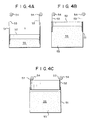
- the foam tank has been explained as having a cylindrical configuration, it may take any proper form, for example, a cubic configuration.
- the foam tank use may be made of a structure in which in the expansion process of the feed solution the expansion level is permitted to be raised together with the corresponding inner wall thereof.
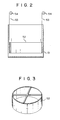
- Fig. 2 is a cross-section showing a foam tank for the manufacture of the polyurethane foam slab in a batch process in accordance with this invention.
- large-sized cylindrical tank 51 has an upper open end and a flat bottom, as in the case of a conventional structure.
- Cylindrical member 52 with both ends opened as shown in Fig. 3 is placed within the cylindrical tank such it can slide along the inner side wall of the cylindrical tank.
- Wire 53 is connected to the upper end of cylindrical member 52, and cylindrical member 52 can be freely raised or lowered by winding or rewinding the wire around rollers 54 by means of a motor, not shown.
- the height, H, of cylindrical member 52 is usually of the order of, properly, 20 to 60 cm.
- a sheet release agent is covered on the inner surface of cylindrical tank 51 as in the conventional foam tank.
- a release agent or release sheet if also covered on the inner surface of cylindrical member 52.
- polyurethane foam slabs can be continuously manufactured in a batch on the apparatus of this invention, thus offering an advantage inherent in the batch system. It is also possible to improve a mass production in high yield in comparison with the conventional batch system. Furthermore, the foam tank used in the manufacture of the polyurethane foam slabs in a batch in accordance with this invention imparts no frictional resistance to the foam feed solution expanded and raised along the inner surface of the foam tank. It is, therefore, possible to manufacture cylindrical polyurethane foam slabs having a flat-topped surface.
Landscapes
- Engineering & Computer Science (AREA)
- Mechanical Engineering (AREA)
- Polyurethanes Or Polyureas (AREA)
- Manufacture Of Porous Articles, And Recovery And Treatment Of Waste Products (AREA)
- Casting Or Compression Moulding Of Plastics Or The Like (AREA)
Claims (3)
- Vorrichtung zur kontinuierlichen Herstellung von Polyurethanschaum in Blöcken, umfassend:
einen zylindrischen Schaumbehälter (10) mit einem flachen Boden und einem offenen Oberende;
eine Trageinrichtung (21), die nahe dem Schaumbehälter (10) verfahrbar angeordnet ist;
einen Rührbehälter (31) für Gemisch, der an der Trageinrichtung (21) befestigt ist;
im Inneren des Rührbehälters (31) angeordnete Rührerflügel (32); und eine Antriebseinrichtung (23) zum Verfahren der Trageinrichtung;
dadurch gekennzeichnet,
daß die Vorrichtung ferner umfaßt:
einen an einer Seitenwand des Schaumbehälters (10) zu öffnenden Einlaß (11), durch den eine Polyurethanschaum-Einsatzlösung in den Behälter (10) einleitbar ist;
ein Ablaufrohr (34), das von einer Seite eines unteren Endabschnitts des Rührbehälters (31) diagonal nach unten verläuft, um den Austrag der Einsatzlösung durch das Ablaufrohr zu ermöglichen;
eine Leitung (41) zum Einleiten einer Polyurethanschaum-Einsatzlösungskomponente in den Rührbehälter (31);
eine Leitung (42) zum Einleiten eines Waschlösungsmittels für die Urethanschaum-Einsatzlösung in den Rührbehälter (31); und
ein in dem Ablaufrohr (34) angeordnetes elektromagnetisches Absperrorgan (35). - Vorrichtung nach Anspruch 1,
dadurch gekennzeichnet,
daß sie ferner eine Antriebseinrichtung aufweist, die unter Zuordnung zu dem Rührbehälter (31) drehbar auf einer relativ zur Trageinrichtung (21) horizontal verlaufenden Welle (30) angeordnet ist, wobei die Antriebseinrichtung ein Schwenken des Rührbehälters (31) um die Welle (30) herum erlaubt, so daß, wenn man die Polyurethanschaum-Einsatzlösung im Rührbehälter (31) in den Schaumbehälter einlaufen läßt, der Rührbehälter (31) vorwärtsgekippt wird, um ein ungehindertes Einlaufen der Polyurethanschaum-Einsatzlösung in den Schaumbehälter (10) zu erlauben. - Vorrichtung nach Anspruch 1,
gekennzeichnet durch
ein zylindrisches Teil (52) mit einem jeweils offenen oberen und unteren Ende, das in dem Schaumbehälter (10) so angeordnet ist, daß es entlang einer Innenseitenwand des Schaumbehälters (10) anhebbar ist, wobei beim Schäumen der in den Schaumbehälter (10) eingeleiteten Urethanschaum-Einsatzlösung das zylindrische Teil (52) aufwärtsbewegbar ist, wobei der Pegel der Polyurethanschaum-Einsatzlösung in einem entsprechenden Ausmaß steigt.
Priority Applications (5)
| Application Number | Priority Date | Filing Date | Title |
|---|---|---|---|
| US06/872,960 US4666393A (en) | 1986-06-13 | 1986-06-11 | Apparatus for manufacturing polyurethane foam slabs in a batch |
| EP86108124A EP0248937B1 (de) | 1986-06-13 | 1986-06-13 | Vorrichtung zur Herstellung von einzelnen Blöcken aus Polyurethanschaum |
| AT86108124T ATE66863T1 (de) | 1986-06-13 | 1986-06-13 | Vorrichtung zur herstellung von einzelnen bloecken aus polyurethanschaum. |
| DE8686108124T DE3681287D1 (de) | 1986-06-13 | 1986-06-13 | Vorrichtung zur herstellung von einzelnen bloecken aus polyurethanschaum. |
| AU58733/86A AU589186B2 (en) | 1986-06-13 | 1986-06-13 | Apparatus for manufacturing polyurethane foam slabs in a batch |
Applications Claiming Priority (1)
| Application Number | Priority Date | Filing Date | Title |
|---|---|---|---|
| EP86108124A EP0248937B1 (de) | 1986-06-13 | 1986-06-13 | Vorrichtung zur Herstellung von einzelnen Blöcken aus Polyurethanschaum |
Publications (3)
| Publication Number | Publication Date |
|---|---|
| EP0248937A2 EP0248937A2 (de) | 1987-12-16 |
| EP0248937A3 EP0248937A3 (en) | 1988-12-14 |
| EP0248937B1 true EP0248937B1 (de) | 1991-09-04 |
Family
ID=8195196
Family Applications (1)
| Application Number | Title | Priority Date | Filing Date |
|---|---|---|---|
| EP86108124A Expired EP0248937B1 (de) | 1986-06-13 | 1986-06-13 | Vorrichtung zur Herstellung von einzelnen Blöcken aus Polyurethanschaum |
Country Status (5)
| Country | Link |
|---|---|
| US (1) | US4666393A (de) |
| EP (1) | EP0248937B1 (de) |
| AT (1) | ATE66863T1 (de) |
| AU (1) | AU589186B2 (de) |
| DE (1) | DE3681287D1 (de) |
Families Citing this family (15)
| Publication number | Priority date | Publication date | Assignee | Title |
|---|---|---|---|---|
| CA1290895C (en) * | 1986-12-25 | 1991-10-15 | Sadao Kumasaka | Method and an apparatus for producing polyurethane foam |
| US5456586A (en) * | 1993-07-07 | 1995-10-10 | Carson; Scott | Apparatus for manufacturing articles made of polyurethane |
| ES2125140B1 (es) * | 1995-07-05 | 2000-01-16 | Alcala Fibras | Mejoras introducidas en equipos mezcladores para la fabricacion de espuma de poliuretano. |
| DE10141619C1 (de) * | 2001-08-24 | 2002-11-28 | Hennecke Gmbh | Verfahren und Vorrichtung zum diskontinuierlichen Herstellen von Polyurethan-Blockschaum |
| AU2006216460A1 (en) * | 2005-02-25 | 2006-08-31 | Nova Chemicals Inc. | Lightweight compositions and articles containing such |
| US8752348B2 (en) * | 2005-02-25 | 2014-06-17 | Syntheon Inc. | Composite pre-formed construction articles |
| US8726594B2 (en) * | 2005-02-25 | 2014-05-20 | Syntheon Inc. | Composite pre-formed building panels |
| EP1871724A2 (de) * | 2005-03-22 | 2008-01-02 | Nova Chemicals Inc. | Leichte betonzusammensetzungen |
| IT1392916B1 (it) * | 2009-02-06 | 2012-04-02 | Fb Design Srl | Dispositivo e procedimento per l'iniezione di materiale di riempimento all'interno di imbarcazioni |
| US7677009B2 (en) * | 2007-02-02 | 2010-03-16 | Nova Chemicals Inc. | Roof truss system |
| US8048219B2 (en) * | 2007-09-20 | 2011-11-01 | Nova Chemicals Inc. | Method of placing concrete |
| US20090078161A1 (en) * | 2007-09-20 | 2009-03-26 | Nova Chemicals Inc. | Methods of minimizing concrete cracking and shrinkage |
| CN102941646B (zh) * | 2012-11-06 | 2014-11-19 | 航天材料及工艺研究所 | 泡沫塑料发泡倍率的评价模具 |
| CN112693024A (zh) * | 2019-10-23 | 2021-04-23 | 中国石油化工股份有限公司 | 一种聚丙烯材料的发泡设备及聚丙烯材料的发泡方法 |
| CN110757712B (zh) * | 2019-10-29 | 2025-01-03 | 江苏森宝节能材料有限公司 | 一种镜框pu发泡设备 |
Family Cites Families (18)
| Publication number | Priority date | Publication date | Assignee | Title |
|---|---|---|---|---|
| US2588151A (en) * | 1948-09-30 | 1952-03-04 | Gen Electric | Apparatus for producing uniform foam structures |
| DE1454878A1 (de) * | 1962-04-13 | 1969-02-20 | Vaterland Werk Friedrich Herfe | Kunststoffmischer mit einem kesselartigen Mischbehaelter und einem ueber dem Behaelterboden angeordneten Mischorgan |
| US3172925A (en) * | 1962-08-31 | 1965-03-09 | Method of distributing foam forming resin within a sandwich structure | |
| US3212128A (en) * | 1963-03-20 | 1965-10-19 | Air Prod & Chem | Mold filling apparatus |
| US3377297A (en) * | 1963-07-15 | 1968-04-09 | Goodyear Tire & Rubber | Method for producing polyurethane foams |
| FR2003090A1 (de) * | 1968-03-02 | 1969-11-07 | Basf Ag | |
| DE1912734B2 (de) * | 1969-03-13 | 1971-04-01 | Farbenfabriken Bayer AG, 5090 Le verkusen | Vorrichtung zum vermischen von schnell miteinander reagie renden komponenten insbesondere fuer die herstellung von schaumstoffen |
| US3642392A (en) * | 1969-03-18 | 1972-02-15 | Uniroyal Inc | Molding system |
| US3590438A (en) * | 1969-03-18 | 1971-07-06 | Uniroyal Inc | Inlet and nozzle apparatus for a mold |
| DE2027190A1 (de) * | 1970-06-03 | 1971-12-09 | Gebert V | Rohrmischverfahren mit Einlegeschlauch zur Plastikschaumherstellung mit intermittierenden Dosiervornchtungen und Kernzahlregelung |
| US4060354A (en) * | 1972-09-11 | 1977-11-29 | Foster Grant Co., Inc. | Apparatus for pre-expanding and molding expandable thermoplastic polymer particles |
| GB1425612A (en) * | 1973-05-29 | 1976-02-18 | Dunlop Ltd | Moulding of plastics foam |
| US3927162A (en) * | 1973-12-20 | 1975-12-16 | Goodyear Tire & Rubber | Method of molding a polyurethane foam involving use of a fan-like spray nozzle |
| AT351242B (de) * | 1974-01-28 | 1979-07-10 | Oesterr Heraklith Ag | Verfahren und form zur diskontinuierlichen herstellung von hartschaumstoffkoerpern |
| DE2901176A1 (de) * | 1979-01-13 | 1980-07-24 | Hennecke Gmbh Maschf | Einrichtung zum diskontinuierlichen herstellen von blockschaumstoff |
| DE3026458C2 (de) * | 1980-07-12 | 1984-04-12 | Maschinenfabrik Hennecke Gmbh, 5090 Leverkusen | Verfahren und Vorrichtung zum Herstellen eines schaumstoffbildenden Reaktionsgemisches |
| HU185699B (en) * | 1982-03-24 | 1985-03-28 | Eszakmagyar Vegyimuevek | Method and apparatus for regulating the shaping of the cross section of freely foamable polimers, preferably poliuretans |
| EP0108167A1 (de) * | 1982-11-01 | 1984-05-16 | ISOMO, naamloze vennotschap | Verfahren zur kontinuierlichen Herstellung von Schichten aus Phenolharzschaum und Vorrichtung zur Durchführung desselben |
-
1986
- 1986-06-11 US US06/872,960 patent/US4666393A/en not_active Expired - Fee Related
- 1986-06-13 EP EP86108124A patent/EP0248937B1/de not_active Expired
- 1986-06-13 AU AU58733/86A patent/AU589186B2/en not_active Ceased
- 1986-06-13 AT AT86108124T patent/ATE66863T1/de not_active IP Right Cessation
- 1986-06-13 DE DE8686108124T patent/DE3681287D1/de not_active Expired - Fee Related
Also Published As
| Publication number | Publication date |
|---|---|
| AU5873386A (en) | 1987-12-17 |
| ATE66863T1 (de) | 1991-09-15 |
| EP0248937A3 (en) | 1988-12-14 |
| DE3681287D1 (de) | 1991-10-10 |
| AU589186B2 (en) | 1989-10-05 |
| EP0248937A2 (de) | 1987-12-16 |
| US4666393A (en) | 1987-05-19 |
Similar Documents
| Publication | Publication Date | Title |
|---|---|---|
| EP0248937B1 (de) | Vorrichtung zur Herstellung von einzelnen Blöcken aus Polyurethanschaum | |
| CN87104799A (zh) | 聚氨酯泡沫生产方法和设备 | |
| CN107336327B (zh) | 一种人造石生产工艺 | |
| CN108330003B (zh) | 一种发泡蜡烛生产线 | |
| CN107553803A (zh) | 一种全自动双色一次发泡成型机 | |
| CN109333387B (zh) | 一种软磨片回转式生产线及其控制方法 | |
| JPS6127168B2 (de) | ||
| CN114102818B (zh) | 变截面预制桩的生产方法和变截面预制桩的生产设备 | |
| CA1245817A (en) | Apparatus for manufacturing polyurethane foam slabs in a batch | |
| US3621522A (en) | Polyurethane foam apparatus | |
| US2724878A (en) | Mold-forming machine | |
| CN213227249U (zh) | 一种汽车防撞块的生产设备 | |
| KR900003737B1 (ko) | 폴리우레탄 포옴 슬라브의 배치식 제조장치 | |
| CN109333388A (zh) | 一种生产软磨片回转式生产线的进出料机构 | |
| JPS61225011A (ja) | ウレタンフオ−ムスラブの連続バツチ式製造装置 | |
| CN86104431A (zh) | 分批制造聚氨基甲酸乙酯泡沫块的设备 | |
| CN108176820B (zh) | 一种纤维冒口成型机及其工作方法 | |
| JPS61102239A (ja) | ウレタンフオ−ムスラブの連続バツチ式製造装置 | |
| CN117261011A (zh) | 一种用于注塑的多组份异形材料混合装置 | |
| CN210308672U (zh) | 真空复模机 | |
| JPH0784015B2 (ja) | ポリウレタンフオ−ムの製造方法 | |
| JPH04305417A (ja) | 注入ヘッドの付着物除去方法およびその装置 | |
| JPS61102240A (ja) | ウレタンフオ−ムスラブの連続バツチ式製造装置 | |
| KR101413343B1 (ko) | 플라스틱 재질로 성형된 사출물의 버어 제거장치 | |
| CN215749974U (zh) | 一种钢铁工业固体废渣与混凝土均匀混合装置 |
Legal Events
| Date | Code | Title | Description |
|---|---|---|---|
| PUAI | Public reference made under article 153(3) epc to a published international application that has entered the european phase |
Free format text: ORIGINAL CODE: 0009012 |
|
| AK | Designated contracting states |
Kind code of ref document: A2 Designated state(s): AT DE FR GB |
|
| PUAL | Search report despatched |
Free format text: ORIGINAL CODE: 0009013 |
|
| AK | Designated contracting states |
Kind code of ref document: A3 Designated state(s): AT DE FR GB |
|
| 17P | Request for examination filed |
Effective date: 19890321 |
|
| 17Q | First examination report despatched |
Effective date: 19891114 |
|
| GRAA | (expected) grant |
Free format text: ORIGINAL CODE: 0009210 |
|
| AK | Designated contracting states |
Kind code of ref document: B1 Designated state(s): AT DE FR GB |
|
| REF | Corresponds to: |
Ref document number: 66863 Country of ref document: AT Date of ref document: 19910915 Kind code of ref document: T |
|
| REF | Corresponds to: |
Ref document number: 3681287 Country of ref document: DE Date of ref document: 19911010 |
|
| ET | Fr: translation filed | ||
| PLBE | No opposition filed within time limit |
Free format text: ORIGINAL CODE: 0009261 |
|
| STAA | Information on the status of an ep patent application or granted ep patent |
Free format text: STATUS: NO OPPOSITION FILED WITHIN TIME LIMIT |
|
| 26N | No opposition filed | ||
| PGFP | Annual fee paid to national office [announced via postgrant information from national office to epo] |
Ref country code: GB Payment date: 19970604 Year of fee payment: 12 |
|
| PGFP | Annual fee paid to national office [announced via postgrant information from national office to epo] |
Ref country code: FR Payment date: 19970611 Year of fee payment: 12 |
|
| PGFP | Annual fee paid to national office [announced via postgrant information from national office to epo] |
Ref country code: AT Payment date: 19980605 Year of fee payment: 13 |
|
| PG25 | Lapsed in a contracting state [announced via postgrant information from national office to epo] |
Ref country code: GB Free format text: LAPSE BECAUSE OF NON-PAYMENT OF DUE FEES Effective date: 19980613 |
|
| PGFP | Annual fee paid to national office [announced via postgrant information from national office to epo] |
Ref country code: DE Payment date: 19980730 Year of fee payment: 13 |
|
| GBPC | Gb: european patent ceased through non-payment of renewal fee |
Effective date: 19980613 |
|
| PG25 | Lapsed in a contracting state [announced via postgrant information from national office to epo] |
Ref country code: FR Free format text: LAPSE BECAUSE OF NON-PAYMENT OF DUE FEES Effective date: 19990226 |
|
| REG | Reference to a national code |
Ref country code: FR Ref legal event code: ST |
|
| PG25 | Lapsed in a contracting state [announced via postgrant information from national office to epo] |
Ref country code: AT Free format text: LAPSE BECAUSE OF NON-PAYMENT OF DUE FEES Effective date: 19990613 |
|
| PG25 | Lapsed in a contracting state [announced via postgrant information from national office to epo] |
Ref country code: DE Free format text: LAPSE BECAUSE OF NON-PAYMENT OF DUE FEES Effective date: 20000503 |