EP0248768A1 - Vorrichtung für eine kontinuierlich arbeitende Spinnmaschine - Google Patents
Vorrichtung für eine kontinuierlich arbeitende Spinnmaschine Download PDFInfo
- Publication number
- EP0248768A1 EP0248768A1 EP87830107A EP87830107A EP0248768A1 EP 0248768 A1 EP0248768 A1 EP 0248768A1 EP 87830107 A EP87830107 A EP 87830107A EP 87830107 A EP87830107 A EP 87830107A EP 0248768 A1 EP0248768 A1 EP 0248768A1
- Authority
- EP
- European Patent Office
- Prior art keywords
- mechanism according
- stretching group
- wire
- cylinders
- formation
- Prior art date
- Legal status (The legal status is an assumption and is not a legal conclusion. Google has not performed a legal analysis and makes no representation as to the accuracy of the status listed.)
- Granted
Links
- 238000009987 spinning Methods 0.000 title description 2
- 230000015572 biosynthetic process Effects 0.000 claims description 21
- 239000002184 metal Substances 0.000 claims description 17
- 230000033001 locomotion Effects 0.000 claims description 16
- 239000010687 lubricating oil Substances 0.000 claims description 5
- 230000005540 biological transmission Effects 0.000 claims description 4
- 230000000694 effects Effects 0.000 claims description 4
- 238000005461 lubrication Methods 0.000 claims description 3
- 239000003921 oil Substances 0.000 claims description 3
- 238000011144 upstream manufacturing Methods 0.000 claims description 3
- 230000002441 reversible effect Effects 0.000 claims description 2
- 230000003068 static effect Effects 0.000 claims description 2
- 238000002347 injection Methods 0.000 claims 2
- 239000007924 injection Substances 0.000 claims 2
- 241000345998 Calamus manan Species 0.000 claims 1
- 238000005452 bending Methods 0.000 claims 1
- 230000007717 exclusion Effects 0.000 claims 1
- 230000037431 insertion Effects 0.000 claims 1
- 238000003780 insertion Methods 0.000 claims 1
- 235000012950 rattan cane Nutrition 0.000 claims 1
- 230000001050 lubricating effect Effects 0.000 abstract 1
- 239000000314 lubricant Substances 0.000 description 3
- 238000004140 cleaning Methods 0.000 description 2
- 238000009826 distribution Methods 0.000 description 1
- 239000000835 fiber Substances 0.000 description 1
- 230000000670 limiting effect Effects 0.000 description 1
- 238000012423 maintenance Methods 0.000 description 1
- 238000004519 manufacturing process Methods 0.000 description 1
- 210000000056 organ Anatomy 0.000 description 1
- 230000001681 protective effect Effects 0.000 description 1
- 238000011084 recovery Methods 0.000 description 1
- 230000002829 reductive effect Effects 0.000 description 1
Images


Classifications
-
- D—TEXTILES; PAPER
- D01—NATURAL OR MAN-MADE THREADS OR FIBRES; SPINNING
- D01H—SPINNING OR TWISTING
- D01H5/00—Drafting machines or arrangements ; Threading of roving into drafting machine
- D01H5/18—Drafting machines or arrangements without fallers or like pinned bars
- D01H5/28—Drafting machines or arrangements without fallers or like pinned bars in which fibres are controlled by inserting twist during drafting
Definitions
- the present invention relates to a mechanism for a continuous spinneret.
- the real pre-torsion devices proposed up to now require two movement controls, one for torsion and the other for stretching, with a consequent expenditure of mechanical means and motive power; they involve technical complications such as excessive congestion, high noise, lubrication problems and also irregularities in stretching and the number of twists per meter in the event of even slight variations in the relative speed between the organs of movement primary torsion and those of the movement that determines the stretch; in addition, they do not allow the automatic introduction of the wick through the stretching group with a stopped or moving spinneret, and finally, in the event of breakage of the wire, downstream of the stretching group, it is wound on the cylinders of said stretching group, forcing, for its recovery, to stop all the spindles of the spinner.
- the present invention aims to eliminate the drawbacks of prior devices and thus allow the adoption of stretch with real pretortion in a continuous spinneret by improving production, facilitating maintenance and ensuring correct operation for very long periods of time without mechanical repair.
- the pressure roller of the stretching group is carried by a removable and balanced slide.
- the means for obtaining the simultaneous stretching and twisting are rigidly assembled together, so that, in addition to having a single control of the movement, the twists are distributed uniformly over the entire piece of wire between the feed group and the stretch group and between the latter and the thread receiving spindle; that the head of the wick, at the outlet of the feeding group, is automatically introduced into the stretching group with the spinner in motion; that the wire in formation is prevented from coming into contact with the fixed part of the spinner; that, in the event of breakage, the wire is prevented from being wound on the cylinders of the stretching group and, moreover, pushed down, vertically, avoiding the centrifugal and aerodynamic effects of the rotating part of the mechanism; that the air flow also allows automatic and continuous cleaning of the stretching group; that it is possible to use a spinner for very long periods of time and continuously without mechanical repair.
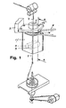
- FIG. 1 shows a schematic view of a mechanism for continuous spinneret according to the invention in the operational arrangement
- Fig 2 shows a section along the line AA in Fig.1
- fig. 3 shows the front view, partially in section, of the mechanism of FIG 2
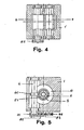
- fig. 4 shows a section along the line BB in FIG. 3
- fig. 5 shows a section along the line CC of FIG. 3
- fig. 6 shows a view in axial vertical section of an improved variant of the mechanism of FIG. 2; fig.
- FIG. 6A shows a vertical sectional view along a plane orthogonal to that of FIG. 6; fig. 6B shows a sectional view along the line DD of FIG. 6; fig. 7A shows a detail, in vertical section, of an alternative embodiment of the internal gear train of the mechanism of FIG. 2; FIG. 7B represents a detail, in vertical section, of another alternative embodiment of the internal gear train of the mechanism of FIG. 2; fig. 7C shows a detail partially in section, of a freewheel reverser for the mechanism of FIG. 2; fig. 8 shows an axial vertical section of an alternative embodiment of the mechanism of FIG. 2; and fig. 9 shows an axial vertical section of an alternative embodiment of the mechanism of FIG. 2.
- a mechanism for a continuous spinneret includes: - A body in two pieces 1,1 ⁇ with a first cavity 10 open upwards and communicating with a second lower cavity 12, which is provided, at the bottom with an orifice 15 for the exit of the wire in formation 7; said body is mounted, by means of bearings 16, on a hollow pin 2 which is in turn fixed vertically to a fixed part 3 of the spinneret and the mouth 13 of which is advantageously flared to falicitate the introduction of the wire in formation 7: the rotational movement of the body 1,1 ⁇ being derived, that is to say obtained from, a control member (not shown) by means of a belt 4 and a corresponding pulley 14.
- Said pin 2 is d 'a single piece with an endless screw 21 and inside, is installed a metal tube 5 coaxial and fixed, by its lower end, to the body 1.
- the pin 2 Near the orifice 13 for introducing the forming wire 7 , the pin 2 is provided with a nozzle 20 inclined downwards, for the introduction of compressed air intended to generate a current of air inside the metal tube 5 for the control of the wire in formation 7 which s 'moves there in the pre-twist and stretching phase.
- 1 ⁇ is housed a shaft 6 with a wheel 60 with helical teeth, which is engaged with said screw 21.
- the rotational movement of the driving cylinder 8 is obtained from the shaft 6 by the intermediary of a gear train 81, 82, 83, 84, 85 whose wheel 83 is advantageously retractable so as to disengage the wheel idler 84 and respectively to engage the wheel 85, in order to reverse the direction of rotation of the cylinders of the stretching group around their axes, and thus to print in thread 7, twists Z and S, respectively: l 'retraction of the wheel 83 being caused, automatically by reversing the direction of rotation of the body 1,1 ⁇ .
- the air stream which exits through the metal tube 5 is directed towards the outlet orifice 15 through the space 91 surrounding the cylinders 8, 9 of the stretching group, cleaning their surface, which moves in the opposite direction from the direction of movement of air stream itself.
- the transmission between the screw 21 and the cylinder 8 of the stretching group makes it possible to obtain the stretching and the pre-twisting of the wire in formation 7 by means of the rotation of the single body 1,1 ⁇ which can be done at high speed and with a low torque.
- the thread obtained is always regular because the stretching group 8, 9 and the rotating 1.1 1, body are rigidly assembled together, so that any regularity errors in the thread which would be due are avoided. to small variations in speed between the two rotating members.
- the number of turns of the body 1, 1 ⁇ , the transmission ratio of the internal gear train 21.60, 81-85, and the diameter of the cylinders of the stretching group 8, 9 can vary so suitable for obtaining in the wire a number of twists per meter between 10 and 400
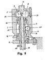
- an improved variant of the mechanism of FIG. 2 includes: (a) a hollow body 1 for receiving a structure 100, which is mounted by means of bearings 16, 16 ⁇ on the hollow pin 2 vertically integral with a fixed part 3 of the spinneret, and supports the driving cylinder 8 of the group of stretch and the gear train 60, 81, 82 ⁇ , 85, intended for transmitting the rotational movement of the body 1, obtained from a belt 4 and a pulley 14, from the drive cylinder 8 in cooperation with the worm screw 21 fixed to said fixed journal 2.
- the walls of said structure 100 delimit , with that of the body 1, three communicating chambers 110 to 112, with the first 110 internal to the structure 100, the second external 111 and the third 112 situated above and of diameter greater than that of the chamber 111.
- Said chambers are intended to contain an appropriate quantity of lubricating oil which is introduced therein via an inlet 140 of the upper chamber 112 and to distribute it to said gear train and to the bearings of the corresponding shafts by the centrifugal effect which derives from the rotation of the body 1.
- an oiling device 150 is fixed to the pin 2, the folded arms from which advantageously provide for the removal of the lubricant which, during the rotation of said body 1, is present on the wall of said chamber 112 , and its distribution, respectively, to the upper bearing 16 and to the worm gear group, toothed wheel 21, 60, from which it falls on the lower bearing 16 ⁇ : a cannula 151 being provided in the structure 100 for the inlet and the possible drainage of the lubricant to and from the bearing of the wheel shaft 82 ⁇ .
- the wire in formation which passes in the metal tube 5 can never be reached by the lubricating oil present in the chamber 110 since the base of the said metal tube is tightly fixed to the structure 100.
- the lubricating oil present in the upper chamber 112 descends through the orifices 113 in the internal chamber 111 and that present in the latter is deposited on the bottom; the quantity is such that its level does not exceed the protective cover or cover 130 of the bearing 131 of the drive roller 8 of the stretching group, so that said roller 8 cannot be reached by the lubricating oil: at this also cooperating with a labyrinth path 115 downstream of said cover.
- Said cover 130 only allows the passage, in dynamic phase, of the small quantity of oil sufficient for the lubrication of the bearing 131; and if the lubricant were to reach said cushion in excessive quantity, it would be automatically evacuated into the chamber 111 through the passage delimited by the sides of the cover 130 and of the wheel 82 ⁇ .
- a tooth 192 provided in correspondence of one end of the slide and to be introduced into a corresponding cavity 193 of the structure 100 and of a rod or latch 194 housed in a sliding manner in correspondence of the other end of the slide and aligned with the above-mentioned spring 191, and the head 195 of which is intended to engage in a corresponding hole passing from the structure 100.
- Said slide 190 is further provided with a counterweight arranged in a corresponding space 197, in a diametrically opposite position relative to the spring 191, so as to be statically balanced.
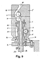
- a compressed air ejector 141 mounted on an arm 142 supported by the fixed part of the spinner, independently of the body 1, the inlet tube 143 of which is positioned downstream of the stretching group 8, 9 and so collecting the wire in formation at the outlet of the latter and guiding it to the outlet 15 of the device.
- the compressed air introduced through the conduit 144 arrives in an annular chamber 145 concentric with the said tube 143 and so as to be flush with the mouth with an inclination of 45 ° or less, this contributing to the blunt edges of the end of the tube 143 and the juxtaposed edge of the ejector.
- Said arm 142 is advantageously articulated on the spinneret to allow, with a vertical rotary movement, to distance and respectively approach the inlet tube 143 to the stretching group 8, 9 in order to allow the removal of the slide 190 above with the pressure roller 9 of the stretching group.
- the body 1, 1 ⁇ with the pin 2 and the stretching group 8, 9 is provided in the tumbled position relative to that of the mechanism of FIG. 2 and the nozzle 20 for the introduction of pressurized air, intended to generate the air flow inside the metal tube 5 and around the cylinders 8, 9 of the stretching group, is provided near the orifice 15 for the outlet of the wire in formation 7.
Landscapes
- Engineering & Computer Science (AREA)
- Mechanical Engineering (AREA)
- Textile Engineering (AREA)
- Spinning Methods And Devices For Manufacturing Artificial Fibers (AREA)
- Spinning Or Twisting Of Yarns (AREA)
- Yarns And Mechanical Finishing Of Yarns Or Ropes (AREA)
- Preliminary Treatment Of Fibers (AREA)
Priority Applications (1)
| Application Number | Priority Date | Filing Date | Title |
|---|---|---|---|
| AT87830107T ATE59863T1 (de) | 1986-04-08 | 1987-03-20 | Vorrichtung fuer eine kontinuierlich arbeitende spinnmaschine. |
Applications Claiming Priority (4)
| Application Number | Priority Date | Filing Date | Title |
|---|---|---|---|
| IT8609365A IT1216227B (it) | 1986-04-08 | 1986-04-08 | Meccanismo per filatoio continuo |
| IT936586 | 1986-04-08 | ||
| IT934487 | 1987-03-12 | ||
| IT09344/87A IT1218537B (it) | 1987-03-12 | 1987-03-12 | Maccanismo perfezionato per filatoi continuo |
Publications (2)
| Publication Number | Publication Date |
|---|---|
| EP0248768A1 true EP0248768A1 (de) | 1987-12-09 |
| EP0248768B1 EP0248768B1 (de) | 1991-01-09 |
Family
ID=26326181
Family Applications (1)
| Application Number | Title | Priority Date | Filing Date |
|---|---|---|---|
| EP87830107A Expired - Lifetime EP0248768B1 (de) | 1986-04-08 | 1987-03-20 | Vorrichtung für eine kontinuierlich arbeitende Spinnmaschine |
Country Status (10)
| Country | Link |
|---|---|
| US (1) | US4735041A (de) |
| EP (1) | EP0248768B1 (de) |
| CN (1) | CN87102606A (de) |
| AT (1) | ATE59863T1 (de) |
| AU (1) | AU591971B2 (de) |
| CA (1) | CA1268084A (de) |
| DE (1) | DE3767220D1 (de) |
| ES (1) | ES2020674B3 (de) |
| MX (1) | MX161021A (de) |
| PL (1) | PL265059A1 (de) |
Cited By (1)
| Publication number | Priority date | Publication date | Assignee | Title |
|---|---|---|---|---|
| WO2007025523A1 (de) * | 2005-08-30 | 2007-03-08 | Koenig Reinhard | Verfahren und vorrichtung zum kompaktieren von bandförmigem fasermaterial und damit arbeitende spinnmaschine |
Families Citing this family (6)
| Publication number | Priority date | Publication date | Assignee | Title |
|---|---|---|---|---|
| AU648255B2 (en) * | 1989-08-09 | 1994-04-21 | Paul P. Cook | Textile processing employing a stretching technique |
| US4961307A (en) * | 1989-08-09 | 1990-10-09 | Cook Paul P | Textile processing employing a stretching technique |
| DE102013113314A1 (de) * | 2013-12-02 | 2015-06-03 | Rieter Ingolstadt Gmbh | Spinnereivorbereitungsmaschine mit einem Streckwerk |
| JP2019019416A (ja) * | 2017-07-12 | 2019-02-07 | 村田機械株式会社 | 空気紡績装置 |
| CN108002013B (zh) * | 2017-12-22 | 2024-05-24 | 宜宾丝丽雅股份有限公司 | 一种粘胶长丝投料装置 |
| CN116494576B (zh) * | 2023-06-29 | 2023-09-08 | 太原理工大学 | 一种可辅助展纱和调节张力的多束纤维螺旋缠绕设备 |
Citations (2)
| Publication number | Priority date | Publication date | Assignee | Title |
|---|---|---|---|---|
| DE2934867A1 (de) * | 1979-08-29 | 1981-03-19 | W. Schlafhorst & Co, 4050 Mönchengladbach | Drehkopf fuer strangfoermiges fasermaterial |
| EP0168357A1 (de) * | 1984-06-08 | 1986-01-15 | Ugo Mallardi | Vorrichtung zum Drehen und gleichzeitigen Verziehen von Lunte auf einer Ringspinnmaschine |
Family Cites Families (10)
| Publication number | Priority date | Publication date | Assignee | Title |
|---|---|---|---|---|
| US617682A (en) * | 1899-01-10 | Spinning mechanism | ||
| US1435912A (en) * | 1922-01-07 | 1922-11-21 | Joseph Downing Mander | Textile spinning, drawing, slubring, roving, and the like machine |
| US1474131A (en) * | 1923-05-12 | 1923-11-13 | Zachariadis Theophilos | Apparatus for drawing and twisting slivers and the like |
| US1922949A (en) * | 1931-04-03 | 1933-08-15 | Harris Thomas | Spinning apparatus |
| US1962265A (en) * | 1931-11-14 | 1934-06-12 | Gessner Ernst Ag | Ring spinning frame |
| US2427955A (en) * | 1946-04-06 | 1947-09-23 | American Viscose Corp | Method and apparatus for converting continuous filaments into spinnable slivers |
| US2688837A (en) * | 1950-12-05 | 1954-09-14 | Hadwich Fritz | Twisting head |
| US2796725A (en) * | 1953-07-23 | 1957-06-25 | Urrutia Tomas | Apparatus for simultaneous twisting and stretching, applicable to continuous machines for spinning carded wool |
| US3114231A (en) * | 1960-02-26 | 1963-12-17 | Novivlas Nv | Method and apparatus for the manufacture of bast fibre yarn |
| US3217483A (en) * | 1962-10-30 | 1965-11-16 | Mitsubishi Shipbuilding & Eng | Spinning machine utilizing centrifugal force and flow of air |
-
1987
- 1987-03-20 AT AT87830107T patent/ATE59863T1/de not_active IP Right Cessation
- 1987-03-20 EP EP87830107A patent/EP0248768B1/de not_active Expired - Lifetime
- 1987-03-20 ES ES87830107T patent/ES2020674B3/es not_active Expired - Lifetime
- 1987-03-20 DE DE8787830107T patent/DE3767220D1/de not_active Expired - Lifetime
- 1987-03-31 MX MX5820A patent/MX161021A/es unknown
- 1987-04-06 AU AU71121/87A patent/AU591971B2/en not_active Ceased
- 1987-04-07 CN CN87102606A patent/CN87102606A/zh active Pending
- 1987-04-07 US US07/035,650 patent/US4735041A/en not_active Expired - Fee Related
- 1987-04-07 CA CA000533977A patent/CA1268084A/en not_active Expired - Lifetime
- 1987-04-08 PL PL1987265059A patent/PL265059A1/xx unknown
Patent Citations (2)
| Publication number | Priority date | Publication date | Assignee | Title |
|---|---|---|---|---|
| DE2934867A1 (de) * | 1979-08-29 | 1981-03-19 | W. Schlafhorst & Co, 4050 Mönchengladbach | Drehkopf fuer strangfoermiges fasermaterial |
| EP0168357A1 (de) * | 1984-06-08 | 1986-01-15 | Ugo Mallardi | Vorrichtung zum Drehen und gleichzeitigen Verziehen von Lunte auf einer Ringspinnmaschine |
Cited By (1)
| Publication number | Priority date | Publication date | Assignee | Title |
|---|---|---|---|---|
| WO2007025523A1 (de) * | 2005-08-30 | 2007-03-08 | Koenig Reinhard | Verfahren und vorrichtung zum kompaktieren von bandförmigem fasermaterial und damit arbeitende spinnmaschine |
Also Published As
| Publication number | Publication date |
|---|---|
| EP0248768B1 (de) | 1991-01-09 |
| ATE59863T1 (de) | 1991-01-15 |
| DE3767220D1 (de) | 1991-02-14 |
| US4735041A (en) | 1988-04-05 |
| PL265059A1 (en) | 1988-06-09 |
| CA1268084A (en) | 1990-04-24 |
| ES2020674B3 (es) | 1991-09-01 |
| AU7112187A (en) | 1987-10-15 |
| CN87102606A (zh) | 1987-11-11 |
| MX161021A (es) | 1990-07-09 |
| AU591971B2 (en) | 1989-12-21 |
Similar Documents
| Publication | Publication Date | Title |
|---|---|---|
| EP0248768B1 (de) | Vorrichtung für eine kontinuierlich arbeitende Spinnmaschine | |
| FR2620462A1 (fr) | Dispositif d'enlevement de la matiere de tas de fibres, notamment de balles de matiere filable | |
| CA2817159C (fr) | Dispositif de formation de la foule et metier a tisser equipe d'un tel dispositif | |
| EP1903133B1 (de) | Vorrichtung zur Betätigung eines flexiblen Webschützen und Webmaschine, die mindestens eine solche Vorrichtung integriert | |
| CH618660A5 (de) | ||
| FR2578242A1 (fr) | Appareil pour la fabrication de fils coupes de fibres de verre | |
| EP0534911A1 (de) | Maschine zur Herstellung von Chenillegarnen | |
| EP0168357B1 (de) | Vorrichtung zum Drehen und gleichzeitigen Verziehen von Lunte auf einer Ringspinnmaschine | |
| FR2674544A1 (fr) | Dispositif a friction pour creer une fausse torsion dans un fil. | |
| FR2879220A1 (fr) | Appareil de preparation de filature destine a alimenter une multiplicite de colonnes de chargement, plus specialement un melangeur, avec de la matiere fibreuse | |
| EP0305305B1 (de) | Vorrichtung zum Erteilen eines Falschdralles an mindestens einem Garn in Fortbewegung | |
| EP1554209A2 (de) | Vorrichtung zum aufwickeln eines fadens auf einem rotierenden wickelträger | |
| EP1451397B1 (de) | Verfahren und vorrichtung zur steuerung von streckwerken einer textilmaschine | |
| BE447557A (de) | ||
| FR2659879A1 (fr) | Dispositif de dressage d'un fil metallique. | |
| BE505135A (de) | ||
| WO2024227698A1 (fr) | Dispositif de broyage d'un produit pateux ou en poudre et en suspension | |
| FR2571346A1 (fr) | Appareil pour le pliage de meches textiles | |
| BE512685A (de) | ||
| BE364431A (de) | ||
| CH295023A (fr) | Rame pour corriger la conformation des tissus. | |
| CH349196A (fr) | Broche de filature à ballon | |
| EP0277438A1 (de) | Karde zur Verarbeitung von Mineralwollefasern | |
| BE513757A (de) | ||
| BE443122A (de) |
Legal Events
| Date | Code | Title | Description |
|---|---|---|---|
| PUAI | Public reference made under article 153(3) epc to a published international application that has entered the european phase |
Free format text: ORIGINAL CODE: 0009012 |
|
| AK | Designated contracting states |
Kind code of ref document: A1 Designated state(s): AT BE CH DE ES FR GB GR IT LI LU NL SE |
|
| 17P | Request for examination filed |
Effective date: 19880123 |
|
| 17Q | First examination report despatched |
Effective date: 19890421 |
|
| GRAA | (expected) grant |
Free format text: ORIGINAL CODE: 0009210 |
|
| AK | Designated contracting states |
Kind code of ref document: B1 Designated state(s): AT BE CH DE ES FR GB GR IT LI LU NL SE |
|
| PG25 | Lapsed in a contracting state [announced via postgrant information from national office to epo] |
Ref country code: SE Effective date: 19910109 Ref country code: NL Effective date: 19910109 Ref country code: GR Free format text: LAPSE BECAUSE OF FAILURE TO SUBMIT A TRANSLATION OF THE DESCRIPTION OR TO PAY THE FEE WITHIN THE PRESCRIBED TIME-LIMIT Effective date: 19910109 Ref country code: AT Effective date: 19910109 |
|
| REF | Corresponds to: |
Ref document number: 59863 Country of ref document: AT Date of ref document: 19910115 Kind code of ref document: T |
|
| ITF | It: translation for a ep patent filed | ||
| GBT | Gb: translation of ep patent filed (gb section 77(6)(a)/1977) | ||
| REF | Corresponds to: |
Ref document number: 3767220 Country of ref document: DE Date of ref document: 19910214 |
|
| PG25 | Lapsed in a contracting state [announced via postgrant information from national office to epo] |
Ref country code: LU Free format text: LAPSE BECAUSE OF NON-PAYMENT OF DUE FEES Effective date: 19910331 |
|
| NLV1 | Nl: lapsed or annulled due to failure to fulfill the requirements of art. 29p and 29m of the patents act | ||
| PLBE | No opposition filed within time limit |
Free format text: ORIGINAL CODE: 0009261 |
|
| STAA | Information on the status of an ep patent application or granted ep patent |
Free format text: STATUS: NO OPPOSITION FILED WITHIN TIME LIMIT |
|
| 26N | No opposition filed | ||
| PGFP | Annual fee paid to national office [announced via postgrant information from national office to epo] |
Ref country code: FR Payment date: 19950224 Year of fee payment: 9 |
|
| PGFP | Annual fee paid to national office [announced via postgrant information from national office to epo] |
Ref country code: GB Payment date: 19950302 Year of fee payment: 9 |
|
| PGFP | Annual fee paid to national office [announced via postgrant information from national office to epo] |
Ref country code: CH Payment date: 19950328 Year of fee payment: 9 |
|
| PGFP | Annual fee paid to national office [announced via postgrant information from national office to epo] |
Ref country code: ES Payment date: 19950330 Year of fee payment: 9 |
|
| PGFP | Annual fee paid to national office [announced via postgrant information from national office to epo] |
Ref country code: DE Payment date: 19950531 Year of fee payment: 9 |
|
| PG25 | Lapsed in a contracting state [announced via postgrant information from national office to epo] |
Ref country code: GB Effective date: 19960320 |
|
| PG25 | Lapsed in a contracting state [announced via postgrant information from national office to epo] |
Ref country code: ES Free format text: LAPSE BECAUSE OF NON-PAYMENT OF DUE FEES Effective date: 19960321 |
|
| PG25 | Lapsed in a contracting state [announced via postgrant information from national office to epo] |
Ref country code: LI Effective date: 19960331 Ref country code: CH Effective date: 19960331 |
|
| GBPC | Gb: european patent ceased through non-payment of renewal fee |
Effective date: 19960320 |
|
| REG | Reference to a national code |
Ref country code: CH Ref legal event code: PL |
|
| PG25 | Lapsed in a contracting state [announced via postgrant information from national office to epo] |
Ref country code: FR Effective date: 19961129 |
|
| PG25 | Lapsed in a contracting state [announced via postgrant information from national office to epo] |
Ref country code: DE Effective date: 19961203 |
|
| REG | Reference to a national code |
Ref country code: FR Ref legal event code: ST |
|
| PGFP | Annual fee paid to national office [announced via postgrant information from national office to epo] |
Ref country code: BE Payment date: 19980518 Year of fee payment: 12 |
|
| REG | Reference to a national code |
Ref country code: ES Ref legal event code: FD2A Effective date: 19990201 |
|
| PG25 | Lapsed in a contracting state [announced via postgrant information from national office to epo] |
Ref country code: BE Free format text: LAPSE BECAUSE OF NON-PAYMENT OF DUE FEES Effective date: 19990331 |
|
| BERE | Be: lapsed |
Owner name: MENICACCI UGO ROBERTO Effective date: 19990331 Owner name: MALLARDI UGO Effective date: 19990331 |
|
| PG25 | Lapsed in a contracting state [announced via postgrant information from national office to epo] |
Ref country code: IT Free format text: LAPSE BECAUSE OF NON-PAYMENT OF DUE FEES Effective date: 20050320 |