EP0248706A2 - Method for making layered glass - Google Patents
Method for making layered glass Download PDFInfo
- Publication number
- EP0248706A2 EP0248706A2 EP87401162A EP87401162A EP0248706A2 EP 0248706 A2 EP0248706 A2 EP 0248706A2 EP 87401162 A EP87401162 A EP 87401162A EP 87401162 A EP87401162 A EP 87401162A EP 0248706 A2 EP0248706 A2 EP 0248706A2
- Authority
- EP
- European Patent Office
- Prior art keywords
- glass
- glass sheet
- plastic film
- adhesive
- cylinders
- Prior art date
- Legal status (The legal status is an assumption and is not a legal conclusion. Google has not performed a legal analysis and makes no representation as to the accuracy of the status listed.)
- Granted
Links
Images


Classifications
-
- B—PERFORMING OPERATIONS; TRANSPORTING
- B32—LAYERED PRODUCTS
- B32B—LAYERED PRODUCTS, i.e. PRODUCTS BUILT-UP OF STRATA OF FLAT OR NON-FLAT, e.g. CELLULAR OR HONEYCOMB, FORM
- B32B17/00—Layered products essentially comprising sheet glass, or glass, slag, or like fibres
- B32B17/06—Layered products essentially comprising sheet glass, or glass, slag, or like fibres comprising glass as the main or only constituent of a layer, next to another layer of a specific material
- B32B17/10—Layered products essentially comprising sheet glass, or glass, slag, or like fibres comprising glass as the main or only constituent of a layer, next to another layer of a specific material of synthetic resin
- B32B17/10005—Layered products essentially comprising sheet glass, or glass, slag, or like fibres comprising glass as the main or only constituent of a layer, next to another layer of a specific material of synthetic resin laminated safety glass or glazing
- B32B17/10807—Making laminated safety glass or glazing; Apparatus therefor
- B32B17/10816—Making laminated safety glass or glazing; Apparatus therefor by pressing
- B32B17/10825—Isostatic pressing, i.e. using non rigid pressure-exerting members against rigid parts
- B32B17/10862—Isostatic pressing, i.e. using non rigid pressure-exerting members against rigid parts using pressing-rolls
-
- B—PERFORMING OPERATIONS; TRANSPORTING
- B32—LAYERED PRODUCTS
- B32B—LAYERED PRODUCTS, i.e. PRODUCTS BUILT-UP OF STRATA OF FLAT OR NON-FLAT, e.g. CELLULAR OR HONEYCOMB, FORM
- B32B17/00—Layered products essentially comprising sheet glass, or glass, slag, or like fibres
- B32B17/06—Layered products essentially comprising sheet glass, or glass, slag, or like fibres comprising glass as the main or only constituent of a layer, next to another layer of a specific material
- B32B17/10—Layered products essentially comprising sheet glass, or glass, slag, or like fibres comprising glass as the main or only constituent of a layer, next to another layer of a specific material of synthetic resin
- B32B17/10005—Layered products essentially comprising sheet glass, or glass, slag, or like fibres comprising glass as the main or only constituent of a layer, next to another layer of a specific material of synthetic resin laminated safety glass or glazing
- B32B17/10009—Layered products essentially comprising sheet glass, or glass, slag, or like fibres comprising glass as the main or only constituent of a layer, next to another layer of a specific material of synthetic resin laminated safety glass or glazing characterized by the number, the constitution or treatment of glass sheets
- B32B17/10036—Layered products essentially comprising sheet glass, or glass, slag, or like fibres comprising glass as the main or only constituent of a layer, next to another layer of a specific material of synthetic resin laminated safety glass or glazing characterized by the number, the constitution or treatment of glass sheets comprising two outer glass sheets
-
- B—PERFORMING OPERATIONS; TRANSPORTING
- B32—LAYERED PRODUCTS
- B32B—LAYERED PRODUCTS, i.e. PRODUCTS BUILT-UP OF STRATA OF FLAT OR NON-FLAT, e.g. CELLULAR OR HONEYCOMB, FORM
- B32B17/00—Layered products essentially comprising sheet glass, or glass, slag, or like fibres
- B32B17/06—Layered products essentially comprising sheet glass, or glass, slag, or like fibres comprising glass as the main or only constituent of a layer, next to another layer of a specific material
- B32B17/10—Layered products essentially comprising sheet glass, or glass, slag, or like fibres comprising glass as the main or only constituent of a layer, next to another layer of a specific material of synthetic resin
- B32B17/10005—Layered products essentially comprising sheet glass, or glass, slag, or like fibres comprising glass as the main or only constituent of a layer, next to another layer of a specific material of synthetic resin laminated safety glass or glazing
- B32B17/1055—Layered products essentially comprising sheet glass, or glass, slag, or like fibres comprising glass as the main or only constituent of a layer, next to another layer of a specific material of synthetic resin laminated safety glass or glazing characterized by the resin layer, i.e. interlayer
- B32B17/10706—Layered products essentially comprising sheet glass, or glass, slag, or like fibres comprising glass as the main or only constituent of a layer, next to another layer of a specific material of synthetic resin laminated safety glass or glazing characterized by the resin layer, i.e. interlayer being photo-polymerized
-
- B—PERFORMING OPERATIONS; TRANSPORTING
- B32—LAYERED PRODUCTS
- B32B—LAYERED PRODUCTS, i.e. PRODUCTS BUILT-UP OF STRATA OF FLAT OR NON-FLAT, e.g. CELLULAR OR HONEYCOMB, FORM
- B32B17/00—Layered products essentially comprising sheet glass, or glass, slag, or like fibres
- B32B17/06—Layered products essentially comprising sheet glass, or glass, slag, or like fibres comprising glass as the main or only constituent of a layer, next to another layer of a specific material
- B32B17/10—Layered products essentially comprising sheet glass, or glass, slag, or like fibres comprising glass as the main or only constituent of a layer, next to another layer of a specific material of synthetic resin
- B32B17/10005—Layered products essentially comprising sheet glass, or glass, slag, or like fibres comprising glass as the main or only constituent of a layer, next to another layer of a specific material of synthetic resin laminated safety glass or glazing
- B32B17/10807—Making laminated safety glass or glazing; Apparatus therefor
- B32B17/10899—Making laminated safety glass or glazing; Apparatus therefor by introducing interlayers of synthetic resin
- B32B17/10935—Making laminated safety glass or glazing; Apparatus therefor by introducing interlayers of synthetic resin as a preformed layer, e.g. formed by extrusion
-
- B—PERFORMING OPERATIONS; TRANSPORTING
- B32—LAYERED PRODUCTS
- B32B—LAYERED PRODUCTS, i.e. PRODUCTS BUILT-UP OF STRATA OF FLAT OR NON-FLAT, e.g. CELLULAR OR HONEYCOMB, FORM
- B32B37/00—Methods or apparatus for laminating, e.g. by curing or by ultrasonic bonding
- B32B37/0007—Methods or apparatus for laminating, e.g. by curing or by ultrasonic bonding involving treatment or provisions in order to avoid deformation or air inclusion, e.g. to improve surface quality
-
- B—PERFORMING OPERATIONS; TRANSPORTING
- B32—LAYERED PRODUCTS
- B32B—LAYERED PRODUCTS, i.e. PRODUCTS BUILT-UP OF STRATA OF FLAT OR NON-FLAT, e.g. CELLULAR OR HONEYCOMB, FORM
- B32B2309/00—Parameters for the laminating or treatment process; Apparatus details
- B32B2309/06—Angles
-
- Y—GENERAL TAGGING OF NEW TECHNOLOGICAL DEVELOPMENTS; GENERAL TAGGING OF CROSS-SECTIONAL TECHNOLOGIES SPANNING OVER SEVERAL SECTIONS OF THE IPC; TECHNICAL SUBJECTS COVERED BY FORMER USPC CROSS-REFERENCE ART COLLECTIONS [XRACs] AND DIGESTS
- Y10—TECHNICAL SUBJECTS COVERED BY FORMER USPC
- Y10T—TECHNICAL SUBJECTS COVERED BY FORMER US CLASSIFICATION
- Y10T156/00—Adhesive bonding and miscellaneous chemical manufacture
- Y10T156/17—Surface bonding means and/or assemblymeans with work feeding or handling means
- Y10T156/1702—For plural parts or plural areas of single part
- Y10T156/1712—Indefinite or running length work
- Y10T156/1722—Means applying fluent adhesive or adhesive activator material between layers
- Y10T156/1727—Plural indefinite length or running length workpieces
- Y10T156/1729—Fluid applied to nip between indefinite length webs
-
- Y—GENERAL TAGGING OF NEW TECHNOLOGICAL DEVELOPMENTS; GENERAL TAGGING OF CROSS-SECTIONAL TECHNOLOGIES SPANNING OVER SEVERAL SECTIONS OF THE IPC; TECHNICAL SUBJECTS COVERED BY FORMER USPC CROSS-REFERENCE ART COLLECTIONS [XRACs] AND DIGESTS
- Y10—TECHNICAL SUBJECTS COVERED BY FORMER USPC
- Y10T—TECHNICAL SUBJECTS COVERED BY FORMER US CLASSIFICATION
- Y10T156/00—Adhesive bonding and miscellaneous chemical manufacture
- Y10T156/17—Surface bonding means and/or assemblymeans with work feeding or handling means
- Y10T156/1702—For plural parts or plural areas of single part
- Y10T156/1712—Indefinite or running length work
- Y10T156/1722—Means applying fluent adhesive or adhesive activator material between layers
- Y10T156/1727—Plural indefinite length or running length workpieces
- Y10T156/1732—Fluid applied to plural workpieces
-
- Y—GENERAL TAGGING OF NEW TECHNOLOGICAL DEVELOPMENTS; GENERAL TAGGING OF CROSS-SECTIONAL TECHNOLOGIES SPANNING OVER SEVERAL SECTIONS OF THE IPC; TECHNICAL SUBJECTS COVERED BY FORMER USPC CROSS-REFERENCE ART COLLECTIONS [XRACs] AND DIGESTS
- Y10—TECHNICAL SUBJECTS COVERED BY FORMER USPC
- Y10T—TECHNICAL SUBJECTS COVERED BY FORMER US CLASSIFICATION
- Y10T156/00—Adhesive bonding and miscellaneous chemical manufacture
- Y10T156/17—Surface bonding means and/or assemblymeans with work feeding or handling means
- Y10T156/1702—For plural parts or plural areas of single part
- Y10T156/1712—Indefinite or running length work
- Y10T156/1741—Progressive continuous bonding press [e.g., roll couples]
Definitions
- the present invention relates to a method for manufacturing laminated glass from at least two glass sheets and an interlayer thickness of a plastic film bonded to the two glass sheets, according to which the plastic film is united by calendering to a glass sheet by means of a hardening adhesive material and this first glass sheet provided with the plastic film is joined by calendering to the second glass sheet also by means of an adhesive material hardening.
- the two glass sheets are united by calendering with a film of thermoplastic material, in particular polyvinyl butyral, during a prejunction process , then they are subjected to a final pressing, hot and under pressure, in an autoclave.
- a film of thermoplastic material in particular polyvinyl butyral
- This process takes place discontinuously and relatively expensive pressure autoclaves are required for this purpose.
- Many attempts have therefore been made to carry out laminated glass manufacturing processes which make it possible to dispense with the autoclave process.
- the interlayer thickness of plastic material is in the form of a film which must be joined to the two glass sheets with the aid of layers of hardening adhesive applied in the liquid state.
- a process of the type specified above is described in document EU-A2 0 108 632.
- the adhesive material is applied to the plastic film placed on a support. plane using extrusion nozzles and in the form of strips spaced from each other.
- the first glass sheet is then placed from above on the plastic film coated with strips of adhesive material and the set of layers, consisting of the planar support, the plastic film coated with adhesive and the plastic sheet.
- upper glass is subjected to a first calendering operation during which the plastic film is united, without forming bubbles, to the overlying glass sheet.
- the laminate formed from the upper glass sheet and the plastic film is then lifted from its support and is turned over so that the plastic film is facing upwards.
- the adhesive material necessary to ensure the junction with the second glass sheet.
- the second sheet of glass which, during a second calendering operation, is united without forming bubbles to the laminate comprising the glass and the plastic material .
- the irradiation operation intended to harden the adhesive layers.
- the adhesive material is applied in excess over the thickness interlayer already glued to the first glass sheet and the second glass sheet is placed on the adhesive material and is glued to the interlayer thickness by a massive calendering pressure, the second glass sheet being temporary
- the adhesive thickness is detached from the thickness of the inlet side of the cylinders by the adhesive material under the influence of the calendering pressure to eliminate the occluded air (DE-AS 27 37 740).
- the particular difficulty in the manufacture of laminated glass according to the above method consists, during the meeting by calendering of the rigid glass sheets, in surely avoiding any occlusion of air.
- the process is essentially carried out with an excess of adhesive material, the excess adhesive material forming a bead between the rigid glass sheets, immediately upstream of the grip of the cylinders and being laterally expelled from between the glass sheets at the time of calendering.
- the excess adhesive material expelled laterally and at the rear end of the glass sheets during calendering fouls the installation and complicates the process.
- the object of the invention is to modify the process mentioned in the preamble so as to make possible a bubble-free joining of the glass sheets in an economical manner and without fouling of the installation by adhesive material leaving at the edges.
- this object is achieved by the fact that the adhesive material for the two layers of adhesive is applied each time in the form of a coherent and uniform film in a final thickness and that the first sheet of glass provided with the plastic film as well as the second glass sheet provided with the adhesive layer are joined by calendering by means of a pair of cylinders with maintenance of an entry opening angle of 2 to 6 °.
- the meeting by calendering of the two sheets of glass can essentially be carried out in any position, insofar as, using adequate mechanical means, care is taken to maintain the necessary opening angle between the two sheets of glass upstream of the grip of the cylinders.
- the two glass sheets are therefore introduced into the calendering area in a planar state from this reciprocal angle, and during the calendering operation, upstream of the calendaring area, they are kept apart from one another. another so that the said opening angle is obtained between them.
- the method is carried out in such a way that, during the joining by calendering of the two glass sheets, the second glass sheet coated with adhesive and whose coated side is facing upwards , and the first glass sheet provided with the plastic film and whose plastic layer is oriented downward, are introduced into the grip of the cylinders, in a substantially horizontal orientation and with the angle d maintained entry opening from 2 to 6 °.
- the support necessary to maintain the opening angle can, in this case, be produced in a particularly simple manner by the fact that the upper glass sheet provided with the plastic layer is supported by rollers and / or support elements in contact with the plastic layer, while the lower glass sheet coated with adhesive material retains its position by the intervention of its own weight.
- the process according to the invention results in a relatively simple manner in a product entirely free of bubbles without fear of fouling of the transport and calendering devices by adhesive material expelled laterally.
- the invention further relates to devices suitable for carrying out the new method.
- glass sheets is essentially meant sheets of silicate glass. If necessary, one of the glass sheets may however also be made of a transparent plastic material, for example a polycarbonate.
- the process according to the invention can, in addition, also be used for the production of laminated glass panes which comprise more than two sheets of glass and / or which, in addition to two sheets of silicate glass, comprise another layer or cover sheet made of transparent plastic.
- laminated glass panes which comprise more than two sheets of glass and / or which, in addition to two sheets of silicate glass, comprise another layer or cover sheet made of transparent plastic.
- Commercial laminated safety glass which can be manufactured using the process according to the invention, consists, for example, of two sheets of silicate glass each 3 to 4 mm thick and an interlayer of about 0.5 mm thick made of plastic film.
- interlayer flexible poly (vinyl chloride) films have been found to be particularly satisfactory, but it is of course also possible to use films of other plastic materials, provided that they have the necessary properties and that they can be glued to the glass surfaces.
- reaction adhesives can be used for this purpose, such as two-component adhesives which, because of the necessary absence of streaks after curing, are applied in the form of very homogeneous mixtures of the reaction components on one of the surfaces to be united.
- one of the two components can, for example, be applied to one of the two surfaces to be joined and the other component can be applied to the other of the two surfaces to be joined so that the hardening reaction takes place with certainty only after the juxtaposition of the two layers to be joined.
- adhesive materials which harden under the action of UV rays.
- Such adhesive materials are described, for example, in patent EU-PS 0 010 355 and in German patent application P 35 23 140.
- adhesive materials have been used with great success based on acrylic resin, as described in the last mentioned German patent application.
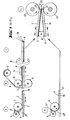
- step A of the method the adhesive material 2 ⁇ is applied to the glass sheet 1 at the rate of the quantity necessary for bonding, in the form of a thin and uniform layer of coherent adhesive 2
- the adhesive described in patent application P 35 23 140 must, for example, be applied in a layer with a thickness of 20 to 50 ⁇ m and, preferably, from 25 to 40 ⁇ m, when a bonding without bubbles perfectly transparent of a flexible poly (vinyl chloride) film must be made, without the calendering, adhesive material is expelled laterally.
- roller coating machines have proven to be particularly advantageous and their working principle is illustrated schematically in FIG. 1.
- Such a roller coating machine comprises two cylindrical rollers 3, 4 rotating in the same direction which are rotatably mounted one next to the other and form a narrow grip 5. These two rollers 3, 4 form above the grip 5 a trough-like hollow which widens upwards and which contains a reserve of liquid adhesive material 2 liquide.
- a thin uniform layer 2 ⁇ is entrained from the reserve of adhesive 2 by the applicator roller 4 which rolls on the glass sheet 1 to be coated and is applied to the surface of the glass sheet 1 in the form of a uniform coherent layer 2.
- the The thickness of the layer or the volume applied can be finely adjusted by modifying the width of the grip 5 of the rollers.
- a flexible poly (vinyl chloride) film approximately 0.5 mm thick 8 is bonded to the course of the next step B of the process on the glass sheet 1 thus coated with the layer of adhesive 2.
- the film 8 is unwound from a roll 9 mounted for rotation and is applied to the adhesive layer 2 by means of a backing roll 10 to which is opposed a support roll 11 intended to support the glass sheet 1.
- the pressure of the pair of rollers 10, 11 is adjusted so that a complete impregnation is obtained, that is to say without gaps and without bubbles of the film 8 by means of the adhesive layer 2.
- a UV radiation source 14 which extends over the entire width of the glass sheet 1 and whose the intensity of the radiation is fixed so that the adhesive layer 2 hardens at the given transport speed. If necessary, it is however not necessary to harden the adhesive layer already at this stage of the process, but rather at a later stage, in particular after the joining by final calendering of the two glass sheets.
- the glass sheet 1 provided with the film 8 is turned over (directional arrow W) so that it is oriented downwards. It turned out that the glass sheet 1 doubled by means film 8 can be transported with the plastic film facing downwards either on a conventional transport path such as a roller conveyor, or a belt conveyor, without prejudice to the process.
- the glass sheet 16 which represents the second single glass sheet intended for the laminated glass pane , is provided in a step D of the process with a coherent adhesive layer of uniform thickness 17 also using a roller coating machine comprising a pair of rollers 3, 4 which contains the adhesive material 17 ⁇ , in the state suitable for casting, in the trough-shaped hollow formed by the two rollers 3, 4.
- the thickness of the adhesive layer 17 corresponds to the thickness of the adhesive layer 2 applied on the glass sheet 1 in step A of the process.
- the glass sheets 1 and 16 thus prepared are now united by calendering without bubbles in step E1 - E3 of the process.
- the front edges 20, 21 of the glass sheets 1, 2 are juxtaposed (E1) in such a way that the two glass sheets form between them an angle ⁇ of 2 to 6 ° and preferably about 3 to 4 °.
- the two glass sheets 1, 16 are introduced into the grip formed by the two cylinders 22, 23.
- the two glass sheets 1, 16 are supported (E2), in an appropriate manner such that the sections of the two sheets glass in front of the cylinders right-of-way are separated by bending from each other and that an opening gap 5 is maintained during the entire calendering operation.
- an elastic bending of the glass sheets occurs over a distance B of about 20 to 40 cm depending on the thickness of the glass sheet.
- the tangents of the flexion line of the upper glass sheet form with the tangents of the flexion line of the lower glass sheet angles which begin at 0 ° in the grip of the cylinders and gradually increase until reaching the value of the maximum opening angle ⁇ .
- the coated glass sheets 1, 16 are joined together by calendering using the pair of cylinders 22, 23 in such a way that at the exit from the grip of the cylinders, a perfectly transparent laminated glass pane is obtained. and without air bubbles included, and it only remains to harden the adhesive layer 17 and, if necessary, the adhesive layer 2.
- a source 25 UV radiation which extends over the entire width of the laminated glass pane and at the intervention of which the adhesive layers harden.
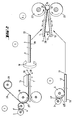
- the conduct of the process illustrated schematically in FIG. 2 is identical in its steps C, D and E1 to E3 to that of the method described above, so that on this point one can refer to the preceding description. Contrary to what happens in the method described above, in the case of the method illustrated in FIG. 2, the application of the adhesive layer and the bonding of the film 28 in a step F of the process are carried out in a single work station.
- the film 28 is again unwound from a supply roller 29 and passes around a lining roller 10 by means of which it is applied to the glass sheet 1.
- the layer of adhesive 2 is however not in this case not applied to the glass sheet 1, but to the film 28.
- the roller coating machine for the adhesive which includes the applicator roller 4 with smooth rubber surface and the metering roller 3 made of steel which rotates in the same direction as the first, is installed immediately next to the lining roller 10, so that the applicator roller 4 is pressed against the film 28 supported by the lining roller 10.
- the applicator roller 4 rotates in the direction of advancement of the film 28 and in the opposite direction to the backing roll 10 so that, during its contact with the film 28, a layer of adhesive of uniform thickness is applied to this film 28.
- Behind the backing roll 10, in the forward direction ent of the glass sheet 1, is installed a source of UV radiation 14 at the intervention of which the adhesive layer 2 hardens.
- the glass sheet 1 is united by calendering in step E1 to E3 of the glass sheet process 16 prepared in step D of the process, as described with reference to FIG. 1.
- step E1 to E3 of the process that is to say the joining by calendering of the two glass sheets 1 and 16 prepared
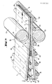
- a device whose main elements are illustrated in FIG. 3, has been shown to be effective.
- This device comprises the pair of pressing cylinders 22, 23 by means of which the two prepared glass sheets 1 and 16 are joined together by calendering under an adjustable pressure, as well as means which ensure that the opening angle ⁇ from 2 to (6) between these two sheets of glass be maintained before entering the calendering area.
- the lower glass sheet 16 is guided, upstream of the calendering area, on a transport path formed by transport rollers 28 and inclined by the angle ⁇ of approximately 2 ° relative to the transport path which is attached behind the calendering area and is formed by the transport rollers 29 or a corresponding conveyor belt.
- the glass sheet 16 is applied on this inclined transport path under the effect of its own weight.
- the upper glass sheet 1 is brought to the calendering grip also on a roller conveyor track.
- the last transport rollers 30 of this upper transport path which are of a relatively small diameter, are arranged in an inclined plane at an angle ⁇ .
- the opening gap S between the two glass sheets 1 and 16 is also reached by a slight deformation of the two glass sheets, the lower glass sheet 16 achieving the slight downward bending necessary by its own weight, while the upper glass sheet is correspondingly supported at its underside.
- the support for the upper glass sheet 1 is provided by a bar 32 which is secured laterally next to the glass sheets.
- the bar 32 is made of rigid metal when bending and has a wedge-shaped section which decreases in the direction of the calendering grip. On its upper surface, it is provided with a sliding layer 23 with a low coefficient of friction which can, for example, be made of poly (tetrafluoroethylene).
- FIG. 4 illustrates by a perspective view once again the entire installation used for the meeting by final calendering of the two prepared glass sheets 1 and 16.
- the devices used to prepare the two glass sheets 1 and 16 to be joined by calendering, are known as such and are therefore not illustrated in detail.
- the lower cylinder 23 of the pair of pressure cylinders is mounted inside the device at a height such that its contact line for the glass sheet 16 lies in the transport plane determined by the transport rollers 29.
- the cylinder upper pressure 22 is maintained by lateral bearings 36 which can slide in height in two vertical slides 51, 52 and are stressed with an adjustable pressure by jacks 38 by means of piston rods 37.
- the jacks 38 are fixed to a frame 39.
- the driving of the two pressing cylinders 22, 23 is carried out by means of a reduction motor 40 whose rotational movement is transmitted from the drive wheel 44 via a double-sided toothed belt 41 to the toothed wheels 42 and 43 of the two cylinders 22 and 23.
- the transport rollers 29 behind the pair of cylinders 22, 23, seen in the direction of advancement of the glass sheets, are mounted on the frame 45 in a horizontal plane.
- the conveyor rollers 28 located in front of the pair of cylinders 22, 23 are mounted on the frame 46 in a plane rising slightly towards the calendering grip so that the last conveyor roller 28 ⁇ located immediately in front of the cylinder 23 occupies the position higher.
- Side supports 48 are mounted on the frame 46 and the support rollers 30 revolve in these supports and are intended to support the upper glass sheet 1.
- side supports 50 are arranged on the frame 46 and the sliding pads 30 are fixed thereto, these pads ensuring, immediately upstream of the calendering grip, the support of the upper glass sheet 1.
- These pads 34 are provided on their upper surface with a lining slip 43, for example poly (tetrafluoroethylene).
- the prepared glass sheets 16 and 1 are placed by hand or with the aid of suitable conveyor devices on the conveyor rollers 28 or on the support rollers 30 and are each oriented in such a way that their front edges touch .
- the drive motor 40 for the pressing cylinders 22, 23 is then energized and the two glass sheets are attacked by the pair of cylinders and are joined by calendering and transferred to the transport rollers 29.
- Above the transport rollers 29 is installed the ray source UV 25 with the intervention of which the adhesive layer (s) harden. Downstream of the UV 25 source, the manufacture of the laminated glass pane is completed.
Abstract
Description
La présente invention concerne un procédé de fabrication de verre feuilleté à partir d'au moins deux feuilles de verre et d'une épaisseur intercalaire d'une pellicule de matière plastique collée aux deux feuilles de verre, selon lequel la pellicule de matière plastique est unie par calandrage à une feuille de verre par l'intermédiaire d'une matière adhésive durcissante et cette première feuille de verre pourvue de la pellicule de matière plastique est unie par calandrage à la second feuille de verre également par l'intermédiaire d'une matière adhésive durcissante.The present invention relates to a method for manufacturing laminated glass from at least two glass sheets and an interlayer thickness of a plastic film bonded to the two glass sheets, according to which the plastic film is united by calendering to a glass sheet by means of a hardening adhesive material and this first glass sheet provided with the plastic film is joined by calendering to the second glass sheet also by means of an adhesive material hardening.
Dans le cas du procédé actuellement utilisé d'une manière générale pour fabriquer des vitres en verre feuilleté, les deux feuilles de verre sont unies par calandrage à une pellicule de matière thermoplastique, en particulier de butyral polyvinylique, au cours d'un processus de préjonction, puis elles sont soumises à un pressage définitif, à chaud et sous pression, dans un autoclave. Ce procédé se déroule de manière discontinue et des autoclaves à pression relativement onéreux sont nécessaires à cet effet. On s'est, par conséquent, maintes fois efforcé de réaliser des procédés de fabrication de verre feuilleté qui permettent de renoncer au processus à autoclave. Dans un procédé de ce genre, l'épaisseur intercalaire en matière plastique a la forme d'une pellicule qui doit être unie aux deux feuilles de verre à l'aide de couches d'adhésif durcissant appliquées à l'état liquide.In the case of the process currently used in general for manufacturing laminated glass panes, the two glass sheets are united by calendering with a film of thermoplastic material, in particular polyvinyl butyral, during a prejunction process , then they are subjected to a final pressing, hot and under pressure, in an autoclave. This process takes place discontinuously and relatively expensive pressure autoclaves are required for this purpose. Many attempts have therefore been made to carry out laminated glass manufacturing processes which make it possible to dispense with the autoclave process. In a process of this kind, the interlayer thickness of plastic material is in the form of a film which must be joined to the two glass sheets with the aid of layers of hardening adhesive applied in the liquid state.
Un procédé du type spécifié plus haut est décrit dans le document EU-A2 0 108 632. Dans ce procédé connu, la matière adhésive est appliquée sur la pellicule de matière plastique disposée sur un support plan à l'aide de buses d'extrusion et sous la forme de bandes espacées les unes des autres. La première feuille de verre est alors posée par le haut sur la pellicule de matière plastique revêtue de bandes de matière adhésive et l'ensemble de couches, constitué du support plan, de la pellicule de matière plastique revêtue d'adhésif et de la feuille de verre supérieure, est soumis à une première opération de calandrage au cours de laquelle la pellicule de matière plastique est unie, sans former de bulles, à la feuille de verre surjacente. Le stratifié formé de la feuille de verre supérieure et de la pellicule de matière plastique est alors soulevé de son support et est retourné de telle sorte que la pellicule de matière plastique soit orientée vers le haut. Sur la pellicule de matière plastique est alors appliquée, également en forme de bandes, la matière adhésive nécessaire pour assurer la jonction à la seconde feuille de verre. Sur l'épaisseur de matière plastique pourvue de matière adhésive en forme de bandes est alors posée la seconde feuille de verre qui, au cours d'une seconde opération de calandrage, est unie sans former de bulles au stratifié comprenant le verre et la matière plastique. A ceci s'ajoute l'opération d'irradiation destinée à faire durcir les couches d'adhésif.A process of the type specified above is described in document EU-A2 0 108 632. In this known process, the adhesive material is applied to the plastic film placed on a support. plane using extrusion nozzles and in the form of strips spaced from each other. The first glass sheet is then placed from above on the plastic film coated with strips of adhesive material and the set of layers, consisting of the planar support, the plastic film coated with adhesive and the plastic sheet. upper glass, is subjected to a first calendering operation during which the plastic film is united, without forming bubbles, to the overlying glass sheet. The laminate formed from the upper glass sheet and the plastic film is then lifted from its support and is turned over so that the plastic film is facing upwards. On the plastic film is then applied, also in the form of strips, the adhesive material necessary to ensure the junction with the second glass sheet. On the thickness of plastic material provided with adhesive material in the form of strips is then placed the second sheet of glass which, during a second calendering operation, is united without forming bubbles to the laminate comprising the glass and the plastic material . To this is added the irradiation operation intended to harden the adhesive layers.
Dans le cas d'un autre procédé connu de fabrication de verre feuilleté à l'aide de matières adhésives liquides pour assurer la jonction de l'épaisseur intercalaire de matière plastique aux feuilles de verre, la matière adhésive est appliquée en excès sur l'épaisseur intercalaire déjà collée à la première feuille de verre et la seconde feuille de verre est posée sur la matière adhésive et est collée à l'épaisseur intercalaire par une pression de calandrage massive, la seconde feuille de verre étant temporai rement décollée de l'épaisseur intercalaire du côté d'entrée des cylindres par la matière adhésive sous l'influence de la pression de calandrage pour éliminer l'air occlus (DE-AS 27 37 740).In the case of another known method of manufacturing laminated glass using liquid adhesive materials to ensure the joining of the interlayer thickness of plastic material to the glass sheets, the adhesive material is applied in excess over the thickness interlayer already glued to the first glass sheet and the second glass sheet is placed on the adhesive material and is glued to the interlayer thickness by a massive calendering pressure, the second glass sheet being temporary The adhesive thickness is detached from the thickness of the inlet side of the cylinders by the adhesive material under the influence of the calendering pressure to eliminate the occluded air (DE-AS 27 37 740).
La difficulté particulière de la fabrication de verre feuilleté selon le procédé précité consiste, lors de la réunion par calandrage des feuilles de verre rigides, à éviter de manière sûre toute occlusion d'air. Dans le cas du procédé connu, on travaille pour cette raison essentiellement avec un excès de matière adhésive, la matière adhésive en excès formant un bourrelet entre les feuilles de verre rigides, immédiatement en amont de l'emprise des cylindres et étant latéralement expulsée d'entre les feuilles de verre au moment du calandrage. Cependant, la matière adhésive en excès expulsée latéralement et à l'extrémité postérieure des feuilles de verre lors du calandrage encrasse l'installation et complique le procédé.The particular difficulty in the manufacture of laminated glass according to the above method consists, during the meeting by calendering of the rigid glass sheets, in surely avoiding any occlusion of air. In the case of the known method, for this reason the process is essentially carried out with an excess of adhesive material, the excess adhesive material forming a bead between the rigid glass sheets, immediately upstream of the grip of the cylinders and being laterally expelled from between the glass sheets at the time of calendering. However, the excess adhesive material expelled laterally and at the rear end of the glass sheets during calendering fouls the installation and complicates the process.
L'invention a pour but de modifier le procédé mentionné dans le préambule de manière à rendre possible un réunion sans bulles des feuilles de verre d'une manière économique et sans encrassement de l'installation par de la matière adhésive sortant au niveau des bords.The object of the invention is to modify the process mentioned in the preamble so as to make possible a bubble-free joining of the glass sheets in an economical manner and without fouling of the installation by adhesive material leaving at the edges.
Suivant l'invention, ce but est réalisé par le fait que la matière adhésive pour les deux couches d'adhésif est appliquée chaque fois sous la forme d'un film cohérent et uniforme en une épaisseur définitive et que la première feuille de verre pourvue de la pellicule de matière plastique ainsi que la seconde feuille de verre pourvue de la couche d'adhésif sont réunies par calandrage au moyen d'une paire de cylindres avec maintien d'un angle d'ouverture d'entrée de 2 à 6°.According to the invention, this object is achieved by the fact that the adhesive material for the two layers of adhesive is applied each time in the form of a coherent and uniform film in a final thickness and that the first sheet of glass provided with the plastic film as well as the second glass sheet provided with the adhesive layer are joined by calendering by means of a pair of cylinders with maintenance of an entry opening angle of 2 to 6 °.
La réunion par calandrage des deux feuilles de verre peut essentiellement s'effectuer dans n'importe quelle position, dans la mesure où, à l'aide de moyens mécaniques adéquats, on veille au maintien de l'angle d'ouverture nécessaire entre les deux feuilles de verre en amont de l'emprise des cylindres. Les deux feuilles de verre sont donc introduites dans l'emprise de calandrage dans un état plan sous cet angle réciproque, et pendant l'opération de calandrage, en amont de l'emprise de calandrage, elles sont maintenues écartées l'une de l'autre de sorte que le dit angle d'ouverture soit obtenu entre elles.The meeting by calendering of the two sheets of glass can essentially be carried out in any position, insofar as, using adequate mechanical means, care is taken to maintain the necessary opening angle between the two sheets of glass upstream of the grip of the cylinders. The two glass sheets are therefore introduced into the calendering area in a planar state from this reciprocal angle, and during the calendering operation, upstream of the calendaring area, they are kept apart from one another. another so that the said opening angle is obtained between them.
Dans une réalisation particulièrement avantageuse de l'invention, le procédé est conduit de telle façon que, lors de la réunion par calandrage des deux feuilles de verre, la seconde feuille de verre enduite d'adhésif et dont la face enduite est orientée vers le haut, et la première feuille de verre pourvue de la pellicule de matière plastique et dont la couche de matière plastique est orientée vers le bas, sont introduites dans l'emprise des cylindres, selon une orientation en substance horizontale et avec maintien de l'angle d'ouverture d'entrée de 2 à 6°.In a particularly advantageous embodiment of the invention, the method is carried out in such a way that, during the joining by calendering of the two glass sheets, the second glass sheet coated with adhesive and whose coated side is facing upwards , and the first glass sheet provided with the plastic film and whose plastic layer is oriented downward, are introduced into the grip of the cylinders, in a substantially horizontal orientation and with the angle d maintained entry opening from 2 to 6 °.
Le support nécessaire pour maintenir l'angle d'ouverture peut, dans ce cas-ci, être réalisé d'une manière particulièrement simple par le fait que la feuille de verre supérieure pourvue de la couche de matière plastique est supportée par des rouleaux et/ou des éléments de support en contact avec la couche de matière plastique, tandis que la feuille de verre inférieure enduite de matière adhésive conserve sa position à l'intervention de son propre poids.The support necessary to maintain the opening angle can, in this case, be produced in a particularly simple manner by the fact that the upper glass sheet provided with the plastic layer is supported by rollers and / or support elements in contact with the plastic layer, while the lower glass sheet coated with adhesive material retains its position by the intervention of its own weight.
Le procédé conforme à l'invention aboutit d'une manière relativement simple à un produit entièrement exempt de bulles sans crainte d'un encrassement des dispositifs de transport et de calandrage par de la matière adhésive expulsée latéralement.The process according to the invention results in a relatively simple manner in a product entirely free of bubbles without fear of fouling of the transport and calendering devices by adhesive material expelled laterally.
L'invention concerne, en outre, des dispositifs appropriés pour l'exécution du nouveau procédé.The invention further relates to devices suitable for carrying out the new method.
Par l'expression "feuilles de verre", on entend essentiellement des feuilles de verre silicaté. Le cas échéant, une des feuilles de verre peut cependant aussi être faite d'une matière plastique transparente, par exemple un polycarbonate. Le procédé conforme à l'invention peut, en outre, aussi être utilisé pour la fabrication de vitres en verre feuilleté qui comprennent plus de deux feuilles de verre et/ou qui, en plus de deux feuilles de verre silicaté, comportent une autre couche ou feuille de recouvrement en une matière plastique transparente. Par souci de simplicité, on ne décrira ci-après que la fabrication d'une vitre en verre feuilleté dans sa forme la plus simple comprenant deux feuilles de verre silicaté et une pellicule de matière plastique intercalaire, mais l'invention n'est cependant limitée à une telle fabrication.By the expression "glass sheets" is essentially meant sheets of silicate glass. If necessary, one of the glass sheets may however also be made of a transparent plastic material, for example a polycarbonate. The process according to the invention can, in addition, also be used for the production of laminated glass panes which comprise more than two sheets of glass and / or which, in addition to two sheets of silicate glass, comprise another layer or cover sheet made of transparent plastic. For the sake of simplicity, we will only describe below the manufacture of a laminated glass pane in its simplest form comprising two sheets of silicate glass and an interlayer plastic film, but the invention is however not limited to such manufacture.
Des réalisations et des développements avantageux de l'invention font l'objet des revendications 2 à 13 et ressortiront, en outre, de la description suivante d'exemples de réalisation préférés, donnée avec référence aux dessins annexés, dans lesquels :
- la Fig. 1 est une vue schématique d'une première forme d'exécution pour le procédé conforme à l'invention;
- la Fig. 2 est également une vue schématique d'une deuxième forme d'exécution pour le procédé conforme à l'invention;
- la Fig. 3 est une vue fragmentaire en perspective de la structure de base d'un dispositif destiné à réunir les feuilles de verre par calandrage selon le procédé conforme à l'invention, et
- la Fig. 4 est une vue en perspective d'ensemble d'un dispositif calandreur et d'une section de durcissement suivante.
- Fig. 1 is a schematic view of a first embodiment for the method according to the invention;
- Fig. 2 is also a schematic view of a second embodiment for the method according to the invention;
- Fig. 3 is a fragmentary perspective view of the basic structure of a device intended to join the glass sheets by calendering according to the process according to the invention, and
- Fig. 4 is an overall perspective view of a calendering device and of a following hardening section.
Le verre de sécurité feuilleté commercial, qui peut être fabriqué au moyen du procédé conforme à l'invention, est constitué, par exemple, de deux feuilles de verre silicaté chacune de 3 à 4 mm d'épaisseur et d'une couche intercalaire d'environ 0,5 mm d'épaisseur faite d'une pellicule de matière plastique. A titre de couche intercalaire, des pellicules de poly(chlorure de vinyle) souples se sont avérées particulièrement satisfaisantes, mais on peut bien entendu aussi utiliser des pellicules en d'autres matières plastiques, dans la mesure où elles possèdent les propiétés nécessaires et qu'elles peuvent être collées aux surfaces du verre.Commercial laminated safety glass, which can be manufactured using the process according to the invention, consists, for example, of two sheets of silicate glass each 3 to 4 mm thick and an interlayer of about 0.5 mm thick made of plastic film. As an interlayer, flexible poly (vinyl chloride) films have been found to be particularly satisfactory, but it is of course also possible to use films of other plastic materials, provided that they have the necessary properties and that they can be glued to the glass surfaces.
Quant à l'adhésif utilisé, il doit s'agir d'un adhésif qui durcit sans dégagement de gaz. Par exemple, on peut utiliser à cet effet, des colles de réaction telles que des colles à deux composants qui, à cause de la nécessaire absence de stries après durcissement, sont appliquées sous la forme de mélanges très homogènes des composants de réaction sur une des surfaces à réunir.As for the adhesive used, it must be an adhesive which hardens without release of gas. For example, reaction adhesives can be used for this purpose, such as two-component adhesives which, because of the necessary absence of streaks after curing, are applied in the form of very homogeneous mixtures of the reaction components on one of the surfaces to be united.
Au lieu de cela, dans le cas d'une colle de réaction à deux composants, un des deux composants peut, par exemple, être appliqué sur une des deux surfaces à réunir et l'autre composant peut être appliqué sur l'autre des deux surfaces à réunir de telle sorte que la réaction de durcissement ne se déroule avec certitude qu'après la juxtaposition des deux couches à réunir.Instead, in the case of a two-component reaction adhesive, one of the two components can, for example, be applied to one of the two surfaces to be joined and the other component can be applied to the other of the two surfaces to be joined so that the hardening reaction takes place with certainty only after the juxtaposition of the two layers to be joined.
Particulièrement satisfaisantes se sont avérées des matières adhésives qui durcissent sous l'action de rayons UV. De telles matières adhésives sont décrites, par exemple, dans le brevet EU-PS 0 010 355 et dans la demande de brevet allemand P 35 23 140. Dans le cas de la réalisation du procédé décrite ci-après, on a utilisé avec un franc succès des matières adhésives à base de résine acrylique, telles qu'elles sont décrites dans la demande de brevet allemand mentionnée en dernier lieu.Particularly satisfactory have been shown to be adhesive materials which harden under the action of UV rays. Such adhesive materials are described, for example, in patent EU-PS 0 010 355 and in German patent application P 35 23 140. In the case of carrying out the process described below, adhesive materials have been used with great success based on acrylic resin, as described in the last mentioned German patent application.
Comme la Fig. 1 le montre clairement, dans l'étape A du procédé, la matière adhésive 2ʹ est appliquée sur la feuille de verre 1 à raison de la quantité nécessaire pour le collage, sous la forme d'une couche d'adhésif cohérente mince et uniforme 2. La colle décrite dans la demande de brevet P 35 23 140 doit, par exemple, être appliquée en une couche d'une épaisseur de 20 à 50 µm et, de préférence, de 25 à 40 µm, lorsqu'un collage sans bulles parfaitement transparent d'une pellicule de poly(chlorure de vinyle) souple doit être réalisé, sans que lors du calandrage, de la matière adhésive soit expulsée latéralement.As Fig. 1 clearly shows, in step A of the method, the adhesive material 2ʹ is applied to the
L'application uniforme de l'adhésif peut être effectuée, par exemple, par des procédés de projection ou de pulvérisation connus dans lesquels la matière adhésive est appliquée en une quantité réglée au moyen d'un ajutage de pulvérisation adéquat. Des machines d'enduction à rouleaux se sont avérées particulièrement avantageuses et leur principe de travail est illustré schématiquement sur la Fig. 1. Une telle machine d'enduction à rouleaux comporte deux rouleaux cylindriques 3, 4 tournant dans la même sens qui sont montés à rotation l'un à côté de l'autre et forment une emprise étroite 5. Ces deux rouleaux 3, 4 forment au-dessus de l'emprise 5 un creux en forme d'auge qui s'élargit vers le haut et qui contient une réserve de matière adhésive liquide 2ʹ. Une mince couche uniforme 2ʺ est entraînée à partir de la réserve d'adhésif 2 par le rouleau applicateur 4 qui roule sur la feuille de verre 1 à enduire et est appliquée sur la surface de la feuille de verre 1 sous la forme d'une couche cohérente uniforme 2. Dans le cas de ces machines d'enduction à rouleaux, l'épaisseur de la couche ou le volume appliqué peut être réglé finement par modification de la largeur de l'emprise 5 des rouleaux.The uniform application of the adhesive can be carried out, for example, by known spraying or spraying methods in which the adhesive material is applied in a controlled amount by means of a suitable spray nozzle. Roller coating machines have proven to be particularly advantageous and their working principle is illustrated schematically in FIG. 1. Such a roller coating machine comprises two
Une pellicule de poly(chlorure de vinyle) souple d'environ 0,5 mm d'épaisseur 8 est collée au course de l'étape suivante B du procédé sur la feuille de verre 1 ainsi enduite de la couche d'adhésif 2. La pellicule 8 est dévidée d'un rouleau 9 monté à rotation et est appliquée sur la couche adhésif 2 au moyen d'un rouleau de doublage 10 auquel est opposé un rouleau de support 11 destiné à soutenir la feuille de verre 1. La pression de la paire de rouleaux 10, 11 est réglée de telle façon qu'on obtienne une imprégnation complète, c'est-à-dire sans lacunes et sans bulles de la pellicule 8 au moyen de la couche d'adhésif 2. Vu dans la direction de transport de la feuille de verre 1, derrière la paire de rouleaux 10, 11 et au-dessus de la feuille de verre, est installée une source de rayonnement UV 14 qui s'étend sur toute la largeur de la feuille de verre 1 et dont l'intensité du rayonnement est fixée de telle sorte que la couche d'adhésif 2 durcisse à la vitesse de transport donnée. Le cas échéant, il n'est cependant pas nécessaire de durcir la couche d'adhésif déjà à ce stade du procédé, mais plutôt à un stade ultérieur, notamment après la réunion par calandrage finale des deux feuilles de verre.A flexible poly (vinyl chloride) film approximately 0.5 mm thick 8 is bonded to the course of the next step B of the process on the
A la sortie du poste de traitement qui réalise l'étape B du procédé, la feuille de verre 1 pourvue de la pellicule 8 est retournée (flèche directionnelle W) de telle sorte qu'elle soit orientée vers le bas. Il s'est avéré que la feuille de verre 1 doublée au moyen de la pellicule 8 peut être transportée avec la pellicule de matière plastique orientée vers le bas indifféremment sur une voie de transport classique comme un transporteur à rouleaux, ou un transporteur à bande, sans porter préjudice au procédé.On leaving the processing station which performs step B of the process, the
Pendant que s'effectue la préparation de la feuille de verre 1 ou, le cas échéant aussi, indépendamment de celle-ci dans le temps, la feuille de verre 16, qui représente la seconde feuille de verre simple destinée à la vitre en verre feuilleté, est pourvue dans une étape D du procédé d'une couche d'adhésif cohérente d'épaisseur uniforme 17 également à l'aide d'une machine d'enduction à rouleaux comportant une paire de rouleaux 3, 4 qui contient la matière adhésive 17ʹ, à l'état apte à la coulée, dans le creux en forme d'auge formé par les deux rouleaux 3, 4. L'épaisseur de la couche d'adhésif 17 correspond à l'épaisseur de la couche d'adhésif 2 appliquée sur la feuille de verre 1 dans l'étape A du procédé.While the
Les feuilles de verre 1 et 16 ainsi préparées sont à présent réunies par calandrage sans bulles dans l'étape E₁ - E₃ du procédé. A cet effet, les bords antérieurs 20, 21 des feuilles de verre 1, 2 sont juxtaposés (E₁) d'une manière telle que les deux feuilles de verre forment entre elles un angle α de 2 à 6° et de préférence d'environ 3 à 4°. Dans cette position relative, les deux feuilles de verre 1, 16 sont introduites dans l'emprise formée par les deux cylindres 22, 23.The
Lorsque les cylindres 22, 23 ont attaqué les feuilles de verre et que l'opération de calandrage proprement dite a débuté, les deux feuilles de verre 1, 16 sont supportées (E₂), d'une manière appropriée telle que les sections des deux feuilles de verre se trouvant devant l'emprise des cylindres soient écartées par flexion l'une de l'autre et qu'un interstice d'ouverture 5 soit maintenu pendant la totalité de l'opération de calandrage. Pendant l'opération de calandrage, une flexion élastique des feuilles de verre se produit sur une distance B d'environ 20 à 40 cm selon l'épaisseur de la feuille de verre. Si l'on considère dans cette zone B les lignes de flexion des deux feuilles de verre et leurs tangentes, les tangentes de la ligne de flexion de la feuille de verre supérieure forment avec les tangentes de la ligne de flexion de la feuille de verre inférieure des angles qui débutent à 0° dans l'emprise des cylindres et croissent progressivement jusqu'à atteindre la valeur de l'angle d'ouverture α maximal.When the
Dans la dernière partie (E₃) de l'opération de calandrage, il ne subsiste qu'un très petit interstice d'ouverture S. Sur la dernière distance d'environ 10 cm à partir du bord postérieur 24, l'angle d'ouverture α ne doit plus être maintenu, car il n'y a plus de risque d'occlusion de bulles d'air.In the last part (E₃) of the calendering operation, there remains only a very small opening gap S. On the last distance of approximately 10 cm from the
Les feuilles de verre 1, 16 revêtues sont réunies par calandrage à l'aide de la paire de cylindres 22, 23 d'une manière telle qu'à la sortie de l'emprise des cylindres, on obtienne une vitre en verre feuilleté parfaitement transparente et sans bulles d'air incluses, et il ne reste qu'à faire durcir la couche d'adhésif 17 et, le cas échéant, la couche d'adhésif 2. A cet effet, derrière la paire de cylindres 23 est installée une source de rayonnement UV 25 qui s'étend sur toute la largeur de la vitre en verre feuilleté et à l'intervention de laquelle les couches d'adhésif durcissent. A la sortie de ce poste de travail qui effectue l'étape E₁ à E₃ du procédé, la fabrication de la vitre en verre feuilleté est terminée.The
La conduite du procédé illustrée schématiquement sur la Fig. 2 est identique dans ses étapes C, D et E₁ à E₃ à celle du procédé décrit plus haut, de sorte que sur ce point on peut se référer à la description précédente. Contrairement à ce qui se passe dans le procédé décrit précédemment, dans le cas du procédé illustré sur la Fig. 2, l'application de la couche d'adhésif et le collage de la pellicule 28 dans une étape F du procédé s'effectuent dans un seul et même poste de travail. La pellicule 28 est à nouveau dévidée d'un rouleau d'alimentation 29 et passe autour d'un rouleau de doublage 10 au moyen duquel elle est appliquée sur la feuille de verre 1. La couche d'adhésif 2 n'est cependant dans ce cas pas appliquée sur la feuille de verre 1, mais sur la pellicule 28. A cet effet, la machine d'enduction à rouleaux pour l'adhésif, qui comprend le rouleau applicateur 4 à surface caoutchouteuse lisse et le rouleau doseur 3 en acier qui tourne dans le même sens que le premier, est installée immédiatement à côté du rouleau de doublage 10, de sorte que le rouleau applicateur 4 est pressé contre la pellicule 28 soutenue par le rouleau de doublage 10. Le rouleau applicateur 4 tourne dans le sens de l'avancement de la pellicule 28 et dans le sens opposé au rouleau de doublage 10 de sorte que, pendant son contact avec la pellicule 28, une couche d'adhésif d'épaisseur uniforme est appliquée sur cette pellicule 28. Derrière le rouleau de doublage 10, dans le sens d'avancement de la feuille de verre 1, est installée une source de rayonnement UV 14 à l'intervention de laquelle la couche d'adhésif 2 durcit.The conduct of the process illustrated schematically in FIG. 2 is identical in its steps C, D and E₁ to E₃ to that of the method described above, so that on this point one can refer to the preceding description. Contrary to what happens in the method described above, in the case of the method illustrated in FIG. 2, the application of the adhesive layer and the bonding of the
Après le retournement (flèche de retournement W) de la feuille de verre 1 ainsi préparée, dans l'étape suivante C du procédé, la feuille de verre 1 est réunie par calandrage dans l'étape E₁ à E₃ du procédé à la feuille de verre 16 préparée dans l'étape D du procédé, comme décrit avec référence à la Fig. 1.After the turning over (turning arrow W) of the
Pour la réalisation pratique de l'étape E₁ à E₃ du procédé, c'est-à-dire la réunion par calandrage des deux feuilles de verre 1 et 16 préparées, un dispositif dont les éléments principaux sont illustrés sur la Fig. 3, s'est avéré efficace. Ce dispositif comporte la paire de cylindres presseurs 22, 23 au moyen de laquelle les deux feuilles de verre 1 et 16 préparées sont réunies par calandrage sous une pression réglable, ainsi que des moyens qui assurent que l'angle d'ouverture α de 2 à 6° entre ces deux feuilles de verre soit maintenu avant l'entrée dans l'emprise de calandrage. La feuille de verre inférieure 16 est guidée, en amont de l'emprise de calandrage, sur une voie de transport formée de rouleaux transporteurs 28 et inclineée de l'angle β d'environ 2° par rapport à la voie de transport qui se rattache à l'arrière de l'emprise de calandrage et est formée des rouleaux transporteurs 29 ou d'une bande transporteuse correspondante. La feuille de verre 16 s'applique sur cette voie de transport inclinée sous l'effet de son propre poids.For the practical realization of step E₁ to E₃ of the process, that is to say the joining by calendering of the two
Au-dessus de la feuille de verre 16, la feuille de verre supérieure 1 est amenée à l'emprise de calandrage également sur une voie de transport à rouleaux. Les derniers rouleaux transporteurs 30 de cette voie de transport supérieure, qui sont d'un diamètre relativement petit, sont disposés dans un plan incliné sous un angle γ. L'interstice d'ouverture S entre les deux feuilles de verre 1 et 16 est également atteint par une légère déformation des deux feuilles de verre, la feuille de verre inférieure 16 atteignant la légère flexion vers le bas nécessaire par son propre poids, tandis que la feuille de verre supérieure est soutenue de manière correspondante au niveau de sa face inférieure. Dans la dernière section immédiatement devant l'emprise de calandrage 26, le support de la feuille de verre supérieure 1 est assuré par une barre 32 qui est assujettie latéralement à côté des feuilles de verre. La barre 32 est en métal rigide à la flexion et présente une section cunéiforme qui va en diminuant en direction de l'emprise de calandrage. Sur sa surface supérieure, elle est pourvue d'une couche de glissement 23 à faible coefficient de friction qui peut, par exemple, être en poly(tétrafluoroéthylène).Above the
Lorsque les feuilles de verre 1, 16 ne sont pas très larges, un soutien de la feuille de verre supérieure 1 sur toute sa largeur n'est pas absolument indispensable. Il suffit dans ce cas, de prévoir simplement de petits patins de glissement cunéiformes 34 des deux côtés, comme illustré sur la Fig. 4.When the
Pour le reste, la Fig. 4 illustre par une vue en perspective encore une fois l'ensemble de l'installation utilisée pour la réunion par calandrage finale des deux feuilles de verre préparées 1 et 16. Les dispositifs utilisés pour préparer les deux feuilles de verre 1 et 16 à réunir par calandrage, sont connus comme tels et ne sont, par conséquent, pas illustrés en détail.For the rest, Fig. 4 illustrates by a perspective view once again the entire installation used for the meeting by final calendering of the two
Le cylindre inférieur 23 de la paire de cylindres de pression est monté à l'intérieur du dispositif à une hauteur telle que sa ligne de contact pour la feuille de verre 16 se situe dans le plan de transport déterminé par les rouleaux transporteurs 29. Le cylindre de pression supérieur 22 est maintenu par des paliers latéraux 36 qui peuvent coulisser en hauteur dans deux glissières verticales 51, 52 et sont sollicités avec une pression réglable par des vérins 38 par l'intermédiaire de tiges de piston 37. Les vérins 38 sont fixés à un bâti 39. L'entraînement des deux cylindres presseurs 22, 23 s'effectue par l'intermédiaire d'un moteur-réducteur 40 dont le mouvement de rotation est transmis à partir de la roue d'entraînement 44 par l'intermédiaire d'une courroie dentée double face 41 aux roues dentées 42 et 43 des deux cylindres 22 et 23.The
Les rouleaux transporteurs 29 derrière la paire de cylindres 22, 23, vus dans le sens d'avancement des feuilles de verre, sont montés sur le bâti 45 dans un plan horizontal. Les rouleaux transporteurs 28 situés devant la paire de cylindres 22, 23 sont montés sur le bâti 46 dans un plan s'élevant légèrement vers l'emprise de calandrage de sorte que le dernier rouleau transporteur 28ʹ situé immédiatement devant le cylindre 23 occupe la position la plus haute.The
Des supports latéraux 48 sont montés sur le bâti 46 et les rouleaux de support 30 tourillonnent dans ces supports et sont destinés à soutenir la feuille de verre supérieure 1. De plus, peu avant le cylindre presseur inférieur 23, des supports latéraux 50 sont disposés sur le bâti 46 et les patins de glissement 30 y sont fixés, ces patins assurant, immédiatement en amont de l'emprise de calandrage, le soutien de la feuille de verre supérieure 1. Ces patins 34 sont pourvus sur leur surface supérieure d'une garniture de glissement 43, par exemple en poly(tétrafluoroéthylène).Side supports 48 are mounted on the
Les feuilles de verre 16 et 1 préparées sont posées à la main ou à l'aide de dispositifs transporteurs adéquats sur les rouleaux transporteurs 28 ou sur les rouleaux de support 30 et sont chaque fois orientées d'une manière telle que leurs bords antérieurs se touchent. Le moteur d'entraînement 40 pour les cylindres presseurs 22, 23 est alors mis sous tension et les deux feuilles de verre sont attaquées par la paire de cylindres et sont réunies par calandrage et transférées sur les rouleaux transporteurs 29. Au-dessus des rouleaux transporteurs 29 est installée la source de rayons UV 25 à l'intervention de laquelle la ou les couches d'adhésif durcissent. En aval de la source de rayons UV 25, la fabrication de la vitre en verre feuilleté est terminée.The
Claims (13)
Priority Applications (1)
| Application Number | Priority Date | Filing Date | Title |
|---|---|---|---|
| AT87401162T ATE67713T1 (en) | 1986-05-28 | 1987-05-22 | PROCESS FOR PRODUCTION OF COMPOSITE DISCS. |
Applications Claiming Priority (2)
| Application Number | Priority Date | Filing Date | Title |
|---|---|---|---|
| DE3618065 | 1986-05-26 | ||
| DE19863618065 DE3618065A1 (en) | 1986-05-28 | 1986-05-28 | METHOD FOR PRODUCING COMPOSITE GLASS |
Publications (3)
| Publication Number | Publication Date |
|---|---|
| EP0248706A2 true EP0248706A2 (en) | 1987-12-09 |
| EP0248706A3 EP0248706A3 (en) | 1988-12-21 |
| EP0248706B1 EP0248706B1 (en) | 1991-09-25 |
Family
ID=6301868
Family Applications (1)
| Application Number | Title | Priority Date | Filing Date |
|---|---|---|---|
| EP87401162A Expired - Lifetime EP0248706B1 (en) | 1986-05-28 | 1987-05-22 | Method for making layered glass |
Country Status (8)
| Country | Link |
|---|---|
| US (1) | US4816096A (en) |
| EP (1) | EP0248706B1 (en) |
| AT (1) | ATE67713T1 (en) |
| BR (1) | BR8702702A (en) |
| CA (1) | CA1311672C (en) |
| DE (2) | DE3618065A1 (en) |
| ES (1) | ES2026917T3 (en) |
| MX (1) | MX168273B (en) |
Cited By (2)
| Publication number | Priority date | Publication date | Assignee | Title |
|---|---|---|---|---|
| EP0319416A2 (en) * | 1987-12-02 | 1989-06-07 | Saint-Gobain Vitrage International | Process and apparatus for coating a sheet of glass with a soft sheet |
| FR2729476A1 (en) * | 1995-01-13 | 1996-07-19 | Sextant Avionique | Seal procedure for plastic layer on optical device |
Families Citing this family (12)
| Publication number | Priority date | Publication date | Assignee | Title |
|---|---|---|---|---|
| IE60859B1 (en) * | 1987-07-10 | 1994-08-24 | Ici Plc | Articles that include glass sheeting |
| GB8918637D0 (en) * | 1989-08-15 | 1989-09-27 | Chelsea Artisans Plc | Articles including thermosetting-powder surface-coatings |
| DE4415878C2 (en) * | 1994-05-05 | 1996-08-14 | Bayerische Motoren Werke Ag | Laminated glass pane, in particular for vehicles |
| DE19505771C1 (en) * | 1995-02-20 | 1996-09-26 | Lenhardt Maschinenbau | System for producing insulating glass panes with plastic-based spacers |
| DE10220299A1 (en) * | 2002-05-07 | 2003-12-04 | Saint Gobain Sekurit D Gmbh | Composite pane with a foil laminate |
| TWI249058B (en) * | 2004-07-15 | 2006-02-11 | Hannstar Display Corp | Apparatus and method of attaching optical films |
| WO2012112774A1 (en) | 2011-02-16 | 2012-08-23 | Casper Thomas J | Venturi device and method |
| USD778667S1 (en) | 2012-02-16 | 2017-02-14 | Thomas J Casper | Venturi device |
| JPWO2018079158A1 (en) * | 2016-10-26 | 2019-09-12 | Agc株式会社 | Manufacturing method of laminate |
| CN112646504B (en) * | 2020-12-15 | 2022-05-03 | 合肥乐凯科技产业有限公司 | Protection cover plate and mobile terminal |
| CN114512563B (en) * | 2022-04-21 | 2022-07-12 | 南通市乐能电力有限公司 | High-efficient solar cell dual glass assembly processing equipment |
| CN116039216B (en) * | 2023-01-10 | 2023-08-08 | 鹤山市博安防火玻璃科技有限公司 | Multi-angle inclined fireproof glass glue injection molding device |
Citations (6)
| Publication number | Priority date | Publication date | Assignee | Title |
|---|---|---|---|---|
| FR847354A (en) * | 1937-12-11 | 1939-10-09 | Method and apparatus for lining laminated glass and similar composite articles | |
| US3518137A (en) * | 1966-10-31 | 1970-06-30 | Mc Donnell Douglas Corp | Method and apparatus for producing safety glass panel assembly |
| US3574030A (en) * | 1962-04-10 | 1971-04-06 | Corning Glass Works | Method of making flexible glass laminates |
| DE3127721A1 (en) * | 1981-07-14 | 1983-02-10 | Battelle-Institut E.V., 6000 Frankfurt | Process and device for the continuous coating of plastics with glass |
| US4427729A (en) * | 1982-04-09 | 1984-01-24 | Messer John A | Glue chipped glass and method |
| CH651878A5 (en) * | 1980-06-12 | 1985-10-15 | Ugo Pacella | Composite safety panel and process for the production thereof |
Family Cites Families (3)
| Publication number | Priority date | Publication date | Assignee | Title |
|---|---|---|---|---|
| US3654039A (en) * | 1970-02-19 | 1972-04-04 | Lumni Strip Inc | Glass laminating procedure apparatus |
| US4347927A (en) * | 1980-06-23 | 1982-09-07 | Libbey-Owens-Ford Company | Sheet aligning apparatus |
| US4683172A (en) * | 1984-08-14 | 1987-07-28 | General Electric Company | Method for making safety or impact resistant laminates |
-
1986
- 1986-05-28 DE DE19863618065 patent/DE3618065A1/en not_active Withdrawn
-
1987
- 1987-05-22 ES ES198787401162T patent/ES2026917T3/en not_active Expired - Lifetime
- 1987-05-22 EP EP87401162A patent/EP0248706B1/en not_active Expired - Lifetime
- 1987-05-22 AT AT87401162T patent/ATE67713T1/en not_active IP Right Cessation
- 1987-05-22 DE DE8787401162T patent/DE3773266D1/en not_active Expired - Fee Related
- 1987-05-26 US US07/053,739 patent/US4816096A/en not_active Expired - Lifetime
- 1987-05-26 MX MX006628A patent/MX168273B/en unknown
- 1987-05-26 BR BR8702702A patent/BR8702702A/en not_active IP Right Cessation
- 1987-05-26 CA CA000538009A patent/CA1311672C/en not_active Expired - Fee Related
Patent Citations (6)
| Publication number | Priority date | Publication date | Assignee | Title |
|---|---|---|---|---|
| FR847354A (en) * | 1937-12-11 | 1939-10-09 | Method and apparatus for lining laminated glass and similar composite articles | |
| US3574030A (en) * | 1962-04-10 | 1971-04-06 | Corning Glass Works | Method of making flexible glass laminates |
| US3518137A (en) * | 1966-10-31 | 1970-06-30 | Mc Donnell Douglas Corp | Method and apparatus for producing safety glass panel assembly |
| CH651878A5 (en) * | 1980-06-12 | 1985-10-15 | Ugo Pacella | Composite safety panel and process for the production thereof |
| DE3127721A1 (en) * | 1981-07-14 | 1983-02-10 | Battelle-Institut E.V., 6000 Frankfurt | Process and device for the continuous coating of plastics with glass |
| US4427729A (en) * | 1982-04-09 | 1984-01-24 | Messer John A | Glue chipped glass and method |
Cited By (3)
| Publication number | Priority date | Publication date | Assignee | Title |
|---|---|---|---|---|
| EP0319416A2 (en) * | 1987-12-02 | 1989-06-07 | Saint-Gobain Vitrage International | Process and apparatus for coating a sheet of glass with a soft sheet |
| EP0319416A3 (en) * | 1987-12-02 | 1989-12-20 | Saint-Gobain Vitrage | Process and apparatus for coating a sheet of glass with a soft sheet |
| FR2729476A1 (en) * | 1995-01-13 | 1996-07-19 | Sextant Avionique | Seal procedure for plastic layer on optical device |
Also Published As
| Publication number | Publication date |
|---|---|
| BR8702702A (en) | 1988-03-01 |
| CA1311672C (en) | 1992-12-22 |
| DE3773266D1 (en) | 1991-10-31 |
| MX168273B (en) | 1993-05-14 |
| EP0248706B1 (en) | 1991-09-25 |
| DE3618065A1 (en) | 1987-12-03 |
| EP0248706A3 (en) | 1988-12-21 |
| US4816096A (en) | 1989-03-28 |
| ATE67713T1 (en) | 1991-10-15 |
| ES2026917T3 (en) | 1992-05-16 |
Similar Documents
| Publication | Publication Date | Title |
|---|---|---|
| EP0248706B1 (en) | Method for making layered glass | |
| EP0015209B1 (en) | Apparatus for assembling glass sheets and/or plastic sheets | |
| CA2019476A1 (en) | Device for pouring of transparent plastic coats, with integrally coloured filter band | |
| FR2589611A1 (en) | ROLL FOR APPLYING A SOLVENT ON PLASTIC LABELS | |
| FR2494177A1 (en) | APPARATUS AND METHOD FOR SEALING ITSELF THERMOPLASTIC FILM | |
| CA1328397C (en) | Method and device for coating a glass sheet with a flexible film | |
| EP0389316B1 (en) | Positioning of a glass sheet on a conveyor | |
| FR2484974A1 (en) | APPARATUS FOR ALIGNING SHEETS | |
| FR2791364A1 (en) | SPREADER | |
| FR2578453A1 (en) | DEVICE FOR COATING BOTH SIDES OF A PAPER BAND | |
| EP0657278B1 (en) | Method and apparatus for making asymmetric laminated glass by calendrage | |
| EP0131483B1 (en) | Method and apparatus for manufacturing plastic films having good optical qualities by coating | |
| EP0038277B1 (en) | Machine for forming a tubular profile | |
| FR2661363A1 (en) | DEVICE FOR DEPOSITING A COATING COMPOSITION LAYER ON A SUBSTRATE BAND. | |
| EP0798113A1 (en) | Method and apparatus for producing panels | |
| EP0038729B1 (en) | Apparatus for applying a coating layer to a continuously travelling web | |
| FR2771375A1 (en) | Continuous packaging procedure for volumes of compressible material | |
| EP0049205B1 (en) | Joining an endless web to a continuously transported mat | |
| EP0271515A1 (en) | Device for guiding a flexible film backfolded on itself. | |
| FR2474005A1 (en) | MACHINE FOR ATTACHING THE TAIL END OF A WOUND TABLECLOTH | |
| FR2458498A1 (en) | METHOD AND INSTALLATION FOR STACKING BAGS, IN PARTICULAR PLASTIC MATERIAL | |
| FR2508351A1 (en) | Feed for applying glue to moving paper strip - has gap between flattening rollers to feed glue transferred to third roller for treating paper | |
| FR2977525A1 (en) | Method for gluing floor covering, pressure sensitive adhesive that is utilized for e.g. bus, involves eliminating longitudinal edge strips adhesive film by withdrawal of set of neutralization bands that carry longitudinal edge strips | |
| LU86729A1 (en) | PREPRESSING APPARATUS AND METHOD | |
| FR2755115A1 (en) | DEVICE FOR TRANSFERRING AND EXTRACTING, IN RELATION TO A WORKSTATION, A FLAN OF HARDWOOD MATERIAL AND PRESS FOR TRANSFORMATION BY APPLYING |
Legal Events
| Date | Code | Title | Description |
|---|---|---|---|
| PUAI | Public reference made under article 153(3) epc to a published international application that has entered the european phase |
Free format text: ORIGINAL CODE: 0009012 |
|
| AK | Designated contracting states |
Kind code of ref document: A2 Designated state(s): AT BE CH DE ES FR GB IT LI SE |
|
| PUAL | Search report despatched |
Free format text: ORIGINAL CODE: 0009013 |
|
| AK | Designated contracting states |
Kind code of ref document: A3 Designated state(s): AT BE CH DE ES FR GB IT LI SE |
|
| 17P | Request for examination filed |
Effective date: 19890531 |
|
| RAP1 | Party data changed (applicant data changed or rights of an application transferred) |
Owner name: VEGLA VEREINIGTE GLASWERKE Owner name: SAINT-GOBAIN VITRAGE INTERNATIONAL |
|
| 17Q | First examination report despatched |
Effective date: 19910220 |
|
| GRAA | (expected) grant |
Free format text: ORIGINAL CODE: 0009210 |
|
| AK | Designated contracting states |
Kind code of ref document: B1 Designated state(s): AT BE CH DE ES FR GB IT LI SE |
|
| REF | Corresponds to: |
Ref document number: 67713 Country of ref document: AT Date of ref document: 19911015 Kind code of ref document: T |
|
| REF | Corresponds to: |
Ref document number: 3773266 Country of ref document: DE Date of ref document: 19911031 |
|
| ITF | It: translation for a ep patent filed |
Owner name: DR. ING. A. RACHELI & C. |
|
| GBT | Gb: translation of ep patent filed (gb section 77(6)(a)/1977) | ||
| REG | Reference to a national code |
Ref country code: ES Ref legal event code: FG2A Ref document number: 2026917 Country of ref document: ES Kind code of ref document: T3 |
|
| PLBE | No opposition filed within time limit |
Free format text: ORIGINAL CODE: 0009261 |
|
| STAA | Information on the status of an ep patent application or granted ep patent |
Free format text: STATUS: NO OPPOSITION FILED WITHIN TIME LIMIT |
|
| 26N | No opposition filed | ||
| EAL | Se: european patent in force in sweden |
Ref document number: 87401162.0 |
|
| PGFP | Annual fee paid to national office [announced via postgrant information from national office to epo] |
Ref country code: DE Payment date: 20010615 Year of fee payment: 15 |
|
| REG | Reference to a national code |
Ref country code: GB Ref legal event code: IF02 |
|
| PG25 | Lapsed in a contracting state [announced via postgrant information from national office to epo] |
Ref country code: DE Free format text: LAPSE BECAUSE OF NON-PAYMENT OF DUE FEES Effective date: 20021203 |
|
| PGFP | Annual fee paid to national office [announced via postgrant information from national office to epo] |
Ref country code: SE Payment date: 20040506 Year of fee payment: 18 |
|
| PGFP | Annual fee paid to national office [announced via postgrant information from national office to epo] |
Ref country code: FR Payment date: 20040512 Year of fee payment: 18 Ref country code: AT Payment date: 20040512 Year of fee payment: 18 |
|
| PGFP | Annual fee paid to national office [announced via postgrant information from national office to epo] |
Ref country code: ES Payment date: 20040518 Year of fee payment: 18 Ref country code: BE Payment date: 20040518 Year of fee payment: 18 |
|
| PGFP | Annual fee paid to national office [announced via postgrant information from national office to epo] |
Ref country code: GB Payment date: 20040519 Year of fee payment: 18 |
|
| PGFP | Annual fee paid to national office [announced via postgrant information from national office to epo] |
Ref country code: CH Payment date: 20040527 Year of fee payment: 18 |
|
| PG25 | Lapsed in a contracting state [announced via postgrant information from national office to epo] |
Ref country code: IT Free format text: LAPSE BECAUSE OF NON-PAYMENT OF DUE FEES;WARNING: LAPSES OF ITALIAN PATENTS WITH EFFECTIVE DATE BEFORE 2007 MAY HAVE OCCURRED AT ANY TIME BEFORE 2007. THE CORRECT EFFECTIVE DATE MAY BE DIFFERENT FROM THE ONE RECORDED. Effective date: 20050522 Ref country code: GB Free format text: LAPSE BECAUSE OF NON-PAYMENT OF DUE FEES Effective date: 20050522 Ref country code: AT Free format text: LAPSE BECAUSE OF NON-PAYMENT OF DUE FEES Effective date: 20050522 |
|
| PG25 | Lapsed in a contracting state [announced via postgrant information from national office to epo] |
Ref country code: SE Free format text: LAPSE BECAUSE OF NON-PAYMENT OF DUE FEES Effective date: 20050523 Ref country code: ES Free format text: LAPSE BECAUSE OF NON-PAYMENT OF DUE FEES Effective date: 20050523 |
|
| PG25 | Lapsed in a contracting state [announced via postgrant information from national office to epo] |
Ref country code: LI Free format text: LAPSE BECAUSE OF NON-PAYMENT OF DUE FEES Effective date: 20050531 Ref country code: CH Free format text: LAPSE BECAUSE OF NON-PAYMENT OF DUE FEES Effective date: 20050531 Ref country code: BE Free format text: LAPSE BECAUSE OF NON-PAYMENT OF DUE FEES Effective date: 20050531 |
|
| BERE | Be: lapsed |
Owner name: *SAINT-GOBAIN VITRAGE INTERNATIONAL Effective date: 20050531 |
|
| REG | Reference to a national code |
Ref country code: CH Ref legal event code: PL |
|
| EUG | Se: european patent has lapsed | ||
| GBPC | Gb: european patent ceased through non-payment of renewal fee |
Effective date: 20050522 |
|
| PG25 | Lapsed in a contracting state [announced via postgrant information from national office to epo] |
Ref country code: FR Free format text: LAPSE BECAUSE OF NON-PAYMENT OF DUE FEES Effective date: 20060131 |
|
| REG | Reference to a national code |
Ref country code: FR Ref legal event code: ST Effective date: 20060131 |
|
| REG | Reference to a national code |
Ref country code: ES Ref legal event code: FD2A Effective date: 20050523 |
|
| BERE | Be: lapsed |
Owner name: *SAINT-GOBAIN VITRAGE INTERNATIONAL Effective date: 20050531 |